
1.4: Directions and Notation
- Page ID
- 7492

The strength of a plane parallel beam of radiation is specified by the radiant flux density F watts per square metre such that F = dP/dA, where A is the area perpendicular to the direction of propagation. Thus F is equal to the net flux πF used by Chandrasekhar, with the important exception that F is used only for a plane parallel beam.
Since the equation of transfer deals only in radiances, we will now address the rather intriguing question, “What is the radiance of a plane parallel beam?”
Figure 2 shows a ray of a plane parallel beam of flux density F incident on the surface of a scattering medium. We shall let the resulting incident radiance be Li, which, using Chandrasekhar’s notation would be specified in position and direction as
\[L_{i}=L\left(0,-\mu_{0}, \varphi_{0}\right), \quad \mu_{0}=\left|\cos \vartheta_{0}\right|\]
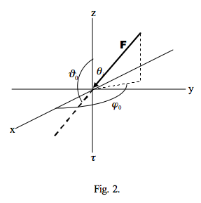
Many authors specify the polar direction of this radiation in terms of an angle of incidence, say i or θi, as the angle between the surface normal and the incident ray, such that i = π - \( \vartheta_0\) and define μ0 as μ0 = cos i.
The angular distribution of F (or, rather, its lack of it) may be specified analytically by making use of the Dirac delta function, which has the property that
\(\int_{-\infty}^{\infty} f(x) \delta(x-a) d x=f(a)\)
and, perhaps more importantly, for any ε > 0
\(\int_{a-\varepsilon}^{a+\varepsilon} f(x) \delta(x-a) d x=f(a).\)
The incident radiance on the surface in the direction (-μ0, φ0) is then1
\[L_{i}=\mathbf{F} \delta\left(\mu-\mu_{0}\right) \delta\left(\varphi-\varphi_{0}\right)\]
Figure 3 shows a reflected beam of radiance Lr where
\[L_{r}=L(0,+\mu, \varphi), \quad \mu=\cos \vartheta\]
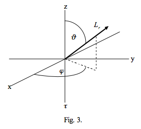
Again, many authors define the polar direction of reflection in terms of an angle of reflection, the angle between the surface normal and the reflected ray, say θr (which is the same as \(\vartheta\)), and define μ as cos θr.
Figure 4 shows a transmitted ray of radiance Lt where
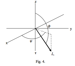
The question then arises: are the values of μ0 and μ, introduced by Chandrasekhar and taken up by others, albeit with different definitions, always positive? The answer to this is, mostly, yes, but care needs to be taken depending on the context in which they occur, as, for example, in the following cases.
Consider the problem of determining the phase angle 0 ≤ α ≤ π between incident and reflected or transmitted directions μ0 and μ, where
\[\cos \alpha=\mu_{0} \mu+\sqrt{\left(1-\mu_{0}^{2}\right)\left(1-\mu^{2}\right)} \cos \left(\varphi-\varphi_{0}\right).\]
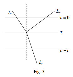
For reflection both m and m0 are positive, but for transmitted rays m must be negative. The phase function p is often expressed in terms of a or cos a. Or, consider, as in figure 5, the optical path lengths of reflected and transmitted radiation from a depth within a medium of optical thickness t. The total optical path for the reflected ray is τ/μ0 + τ/μr and for the transmitted ray τ/μ0 + (t - τ)/μt in which μ0, μr and μt are all positive.
1If equation (7) bothers you in that its right hand side does not appear to have units of radiance, then do not worry; in chapter 2 we will demonstrate that indeed it does have such units.