
12.1: Introduction to Momentum and the Flow of Mass
- Page ID
- 24494

Even though the release was pulled, the rocket did not rise at first, but the flame came out, and there was a steady roar. After a number of seconds it rose, slowly until it cleared the flame, and then at express-train speed, curving over to the left, and striking the ice and snow, still going at a rapid rate. It looked almost magical as it rose, without any appreciably greater noise or flame, as if it said, “I've been here long enough; I think I'll be going somewhere else, if you don't mind.”
Robert Goddard
Preface: The Challenger Flight
When the Rogers Commission in 1986 investigated the Challenger disaster, a commission member, physicist Richard Feynman, made an extraordinary demonstration during the hearings.
“He (Feynman) also learned that rubber used to seal the solid rocket booster joints using O-rings, failed to expand when the temperature was at or below 32 degrees F (0 degrees C). The temperature at the time of the Challenger liftoff was 32 degrees F. Feynman now believed that he had the solution, but to test it, he dropped a piece of the O-ring material, squeezed with a C-clamp to simulate the actual conditions of the shuttle, into a glass of ice water. Ice, of course, is 32 degrees F. At this point one needs to understand exactly what role the O-rings play in the solid rocket booster (SRB) joints. When the material in the SRB start to heat up, it expands and pushes against the sides of the SRB. If there is an opening in a joint in the SRB, the gas tries to escape through that opening (think of it like water in a tea kettle escaping through the spout.) This leak in the Challenger's SRB was easily visible as a small flicker in a launch photo. This flicker turned into a flame and began heating the fuel tank, which then ruptured. When this happened, the fuel tank released liquid hydrogen into the atmosphere where it exploded. As Feynman explained, because the O-rings cannot expand in 32 degree weather, the gas finds gaps in the joints, which led to the explosion of the booster and then the shuttle itself.”
In the Report of the Presidential Commission on the Space Shuttle Challenger Accident (1986), Appendix F - Personal observations on the reliability of the Shuttle, Feynman wrote
The Challenger flight is an excellent example. … The O-rings of the Solid Rocket Boosters were not designed to erode. Erosion was a clue that something was wrong. Erosion was not something from which safety can be inferred. There was no way, without full understanding, that one could have confidence that conditions the next time might not produce erosion three times more severe than the time before. Nevertheless, officials fooled themselves into thinking they had such understanding and confidence, in spite of the peculiar variations from case to case. A mathematical model was made to calculate erosion. This was a model based not on physical understanding but on empirical curve fitting. To be more detailed, it was supposed a stream of hot gas impinged on the O-ring material, and the heat was determined at the point of stagnation (so far, with reasonable physical, thermodynamic laws). But to determine how much rubber eroded it was assumed this depended only on this heat by a formula suggested by data on a similar material. A logarithmic plot suggested a straight line, so it was supposed that the erosion varied as the .58 power of the heat, the .58 being determined by a nearest fit. At any rate, adjusting some other numbers, it was determined that the model agreed with the erosion (to depth of one-third the radius of the ring). There is nothing much so wrong with this as believing the answer! Uncertainties appear everywhere. How strong the gas stream might be was unpredictable, it depended on holes formed in the putty. Blow-by showed that the ring might fail even though not, or only partially eroded through. The empirical formula was known to be uncertain, for it did not go directly through the very data points by which it was determined. There were a cloud of points some twice above, and some twice below the fitted curve, so erosions twice predicted were reasonable from that cause alone. Similar uncertainties surrounded the other constants in the formula, etc., etc. When using a mathematical model careful attention must be given to uncertainties in the model. ...
In any event this has had very unfortunate consequences, the most serious of which is to encourage ordinary citizens to fly in such a dangerous machine, as if it had attained the safety of an ordinary airliner. The astronauts, like test pilots, should know their risks, and we honor them for their courage. Who can doubt that McAuliffe was equally a person of great courage, who was closer to an awareness of the true risk than NASA management would have us believe? Let us make recommendations to ensure that NASA officials deal in a world of reality in understanding technological weaknesses and imperfections well enough to be actively trying to eliminate them. …. For a successful technology, reality must take precedence over public relations, for nature cannot be fooled.
So far we have restricted ourselves to considering systems consisting of discrete objects or point-like objects that have fixed amounts of mass. We shall now consider systems in which material flows between the objects in the system, for example we shall consider coal falling from a hopper into a moving railroad car, sand leaking from railroad car fuel, grain moving forward into a railroad car, and fuel ejected from the back of a rocket, In each of these examples material is continuously flows into or out of an object. We have already shown that the total external force causes the momentum of a system to change,
\[\overrightarrow{\mathbf{F}}_{\mathrm{ext}}^{\text {total }}=\frac{d \overrightarrow{\mathbf{p}}_{\text {system }}}{d t} \nonumber \]
We shall analyze how the momentum of the constituent elements our system change over a time interval \([t, t+\Delta t]\), and then consider the limit as \(\Delta t \rightarrow 0\). We can then explicit calculate the derivative on the right hand side of Equation (12.2.1) and Equation (12.2.1) becomes
\[\overrightarrow{\mathbf{F}}_{\mathrm{ext}}^{\text {total }}=\frac{d \overrightarrow{\mathbf{p}}_{\text {system }}}{d t}=\lim _{\Delta t \rightarrow 0} \frac{\Delta \overrightarrow{\mathbf{p}}_{\text {system }}}{\Delta t}=\lim _{\Delta t \rightarrow 0} \frac{\overrightarrow{\mathbf{p}}_{\text {system }}(t+\Delta t)-\overrightarrow{\mathbf{p}}_{\text {system }}(t)}{\Delta t} \nonumber \]
We need to be very careful how we apply this generalized version of Newton’s Second Law to systems in which mass flows between constituent objects. In particular, when we isolate elements as part of our system we must be careful to identify the mass Δm of the material that continuous flows in or out of an object that is part of our system during the time interval Δt under consideration.
We shall consider four categories of mass flow problems that are characterized by the momentum transfer of the material of mass Δm .
Transfer of Material into an Object, but no Transfer of Momentum
Consider for example rain falling vertically downward with speed \(u\) into car of mass m moving forward with speed \(v\). A small amount of falling rain \(\Delta m_{r}\) has no component of momentum in the direction of motion of the car. There is a transfer of rain into the car but no transfer of momentum in the direction of motion of the car (Figure 12.1).
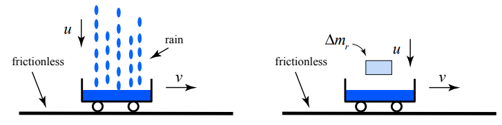
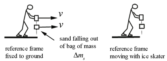
Transfer of Material Out of an Object, but no Transfer of Momentum
The material continually leaves the object but it does not transport any momentum away from the object in the direction of motion of the object (Figure 12.2). Consider an ice skater gliding on ice at speed v holding a bag of sand that is leaking straight down with respect to the moving skater. The sand continually leaves the bag but it does not transport any momentum away from the bag in the direction of motion of the object. In Figure 12.2, sand of mass \(\Delta m_{s}\) leaves the bag.
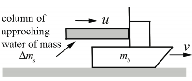
Transfer of Material Impulses Object Via Transfer of Momentum
Suppose a fire hose is used to put out a fire on a boat of mass \(m_{b}\). Assume the column of water moves horizontally with speed u . The incoming water continually hits the boat propelling it forward. During the time interval \(\Delta t\) a column of water of mass \(\Delta m_{s}\) will hit the boat that is moving forward with speed v increasing it’s speed (Figure 12.3).
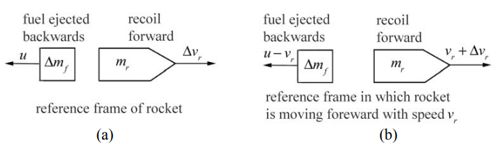
Material Continually Ejected From Object results in Recoil of Object
When fuel of mass \(\Delta m_{f}\) is ejected from the back of a rocket with speed u relative to the rocket, the rocket of mass \(m_{r}\) recoils forward. Figure 12.4a shows the recoil of the rocket in the reference frame of the rocket. The rocket recoils forward with speed \(\Delta v_{r}\). In a reference frame in which the rocket is moving forward with speed \(v_{r}\), then the speed after recoil is \(v_{r}+\Delta v_{r}\). The speed of the backwardly ejected fuel is \(u-v_{r}\) (Figure 12.4b).
We must carefully identify the momentum of the object and the material transferred at time t in order to determine \(\overrightarrow{\mathbf{p}}_{\text {system }}(t)\). We must also identify the momentum of the object and the material transferred at time \(t+\Delta t\) in order to determine \(\overrightarrow{\mathbf{p}}_{\text {system }}(t+\Delta t)\) as well. Recall that when we defined the momentum of a system, we assumed that the mass of the system remain constant. Therefore we cannot ignore the momentum of the transferred material at time \(t+\Delta t\) even though it may have left the object; it is still part of our system (or at time t even though it has not flowed into the object yet).