
20.2: Constrained Motion - Translation and Rotation
- Page ID
- 24551

We shall encounter many examples of a rolling object whose motion is constrained. For example we will study the motion of an object rolling along a level or inclined surface and the motion of a yo-yo unwinding and winding along a string. We will examine the constraint conditions between the translational quantities that describe the motion of the center of mass, displacement, velocity and acceleration, and the rotational quantities that describe the motion about the center of mass, angular displacement, angular velocity and angular acceleration. We begin with a discussion about the rotation and translation of a rolling wheel.

Consider a wheel of radius R is rolling in a straight line (Figure 20.2). The center of mass of the wheel is moving in a straight line at a constant velocity \(\overrightarrow{\mathbf{V}}_{c m}\). Let’s analyze the motion of a point P on the rim of the wheel.
Let \(\overrightarrow{\mathbf{v}}_{P}\) denote the velocity of a point P on the rim of the wheel with respect to reference frame O at rest with respect to the ground (Figure 20.3a). Let \(\overrightarrow{\mathbf{V}}_{P}^{\prime}\) denote the velocity of the point P on the rim with respect to the center of mass reference frame \(O_{c m}\) moving with velocity \(\overrightarrow{\mathbf{V}}_{c m}\) with respect to at O (Figure 20.3b). (You should review the definition of the center of mass reference frame in Chapter 15.2.1.) We can use the law of addition of velocities (Equation15.2.4) to relate these three velocities,
\[\overrightarrow{\mathbf{v}}_{P}=\overrightarrow{\mathbf{v}}_{P}^{\prime}+\overrightarrow{\mathbf{V}}_{c m} \nonumber \]
Let’s choose Cartesian coordinates for the translation motion and polar coordinates for the motion about the center of mass as shown in Figure 20.3.

The center of mass velocity in the reference frame fixed to the ground is given by
\[\overrightarrow{\mathbf{V}}_{c m}=V_{\mathrm{cm}} \hat{\mathbf{i}} \nonumber \]
where \(V_{\mathrm{cm}}\) is the speed of the center of mass. The position of the center of mass in the reference frame fixed to the ground is given by
\[\overrightarrow{\mathbf{R}}_{\mathrm{cm}}(t)=\left(X_{\mathrm{cm}, 0}+V_{\mathrm{cm}} t\right) \hat{\mathbf{i}} \nonumber \]
where \(X_{\mathrm{cm}, 0}\) is the initial x -component of the center of mass at \(t=0\) The angular velocity of the wheel in the center of mass reference frame is given by
\[\vec{\omega}_{\mathrm{cm}}=\omega_{\mathrm{cm}} \hat{\mathbf{k}} \nonumber \]
where \(\omega_{\mathrm{cm}}\) is the angular speed. The point P on the rim is undergoing uniform circular motion with the velocity in the center of mass reference frame given by
\[\overrightarrow{\mathbf{v}}_{P}^{\prime}=R \omega_{\mathrm{cm}} \hat{\boldsymbol{\theta}} \nonumber \]
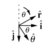
If we want to use the law of addition of velocities then we should express \(\overrightarrow{\mathbf{v}}_{P}^{\prime}=R \omega_{\mathrm{cm}} \hat{\boldsymbol{\theta}}\) in Cartesian coordinates. Assume that at \(t=0, \theta(t=0)=0\) i.e. the point P is at the top of the wheel at t = 0 . Then the unit vectors in polar coordinates satisfy (Figure 20.4)
\[\begin{array}{l}
\hat{\mathbf{r}}=\sin \theta \hat{\mathbf{i}}-\cos \theta \hat{\mathbf{j}} \\
\hat{\mathbf{\theta}}=\cos \theta \hat{\mathbf{i}}+\sin \theta \hat{\mathbf{j}}
\end{array} \nonumber \]
Therefore the velocity of the point P on the rim in the center of mass reference frame is given by
\[\overrightarrow{\mathbf{v}}_{P}^{\prime}=R \omega_{\mathrm{cm}} \hat{\boldsymbol{\theta}}=R \omega_{\mathrm{cm}}(\cos \theta \hat{\mathbf{i}}-\sin \theta \hat{\mathbf{j}}) \nonumber \]
Now substitute Equations (20.2.2) and (20.2.7) into Equation (20.2.1) for the velocity of a point P on the rim in the reference frame fixed to the ground
\[\begin{aligned}
\overrightarrow{\mathbf{v}}_{P} &=R \omega_{\mathrm{cm}}(\cos \theta \hat{\mathbf{i}}+\sin \theta \hat{\mathbf{j}})+V_{\mathrm{cm}} \hat{\mathbf{i}} \\
&=\left(V_{\mathrm{cm}}+R \omega_{\mathrm{cm}} \cos \theta\right) \hat{\mathbf{i}}+R \omega_{\mathrm{cm}} \sin \theta \hat{\mathbf{j}}
\end{aligned} \nonumber \]
The point P is in contact with the ground when \(\theta=\pi\). At that instant the velocity of a point P on the rim in the reference frame fixed to the ground is
\[\overrightarrow{\mathbf{v}}_{P}(\theta=\pi)=\left(V_{\mathrm{cm}}-R \omega_{\mathrm{cm}}\right) \hat{\mathbf{i}} \nonumber \]
What velocity does the observer at rest on the ground measure for the point on the rim when that point is in contact with the ground? In order to understand the relationship between \(V_{\mathrm{cm}}\) and \(\omega_{c m}\), we consider the displacement of the center of mass for a small time interval \(\Delta t\) (Figure 20.5).

From Equation (20.2.3) the x -component of the displacement of the center of mass is
\[\Delta X_{\mathrm{cm}}=V_{\mathrm{cm}} \Delta t \nonumber \]
The point P on the rim in the center of mass reference frame is undergoing circular motion (Figure 20.6).

In the center of mass reference frame, the magnitude of the tangential displacement is given by the arc length subtended by the angular displacement \(\Delta \theta=\omega_{\mathrm{cm}} \Delta t\)
\[\Delta s=R \Delta \theta=R \omega_{\mathrm{cm}} \Delta t \nonumber \]
Case 1: if the x -component of the displacement of the center of mass is equal to the arc length subtended by \(\Delta \theta\), then the wheel is rolling without slipping or skidding, rolling without slipping for short, along the surface with
\[\Delta X_{\mathrm{cm}}=\Delta s \nonumber \]
Substitute Equation (20.2.10) and Equation (20.2.11) into Equation (20.2.12) and divide through by \(\Delta t\). Then the rolling without slipping condition becomes
\[V_{\mathrm{cm}}=R \omega_{\mathrm{cm}}, \quad(\text { rolling without slipping }) \nonumber \]
Case 2: if the x -component of the displacement of the center of mass is greater than the arc length subtended by \(\Delta \theta\), then the wheel is skidding along the surface with
\[\Delta X_{\mathrm{cm}}>\Delta s \nonumber \]
Substitute Equations (20.2.10) and (20.2.11) into Equation (20.2.14) and divide through by \(\Delta t\), then
\[V_{\mathrm{cm}}>R \omega_{\mathrm{cm}}, \quad(\text { skidding }) \nonumber \]
Case 3: if the x -component of the displacement of the center of mass is less than the arc length subtended by \(\Delta \theta\), then the wheel is slipping along the surface with
\[\Delta X_{\mathrm{cm}}<\Delta s \nonumber \]
Arguing as above the slipping condition becomes
\[V_{\mathrm{cm}}<R \omega_{\mathrm{cm}}, \quad \text { (slipping) } \nonumber \]
Rolling without slipping
When a wheel is rolling without slipping, the velocity of a point P on the rim is zero when it is in contact with the ground. In Equation (20.2.9) set \(\theta=\pi\),
\[\overrightarrow{\mathbf{v}}_{P}(\theta=\pi)=\left(V_{\mathrm{cm}}-R \omega_{\mathrm{cm}}\right) \hat{\mathbf{i}}=\left(R \omega_{\mathrm{cm}}-R \omega_{\mathrm{cm}}\right) \hat{\mathbf{i}}=\overrightarrow{\mathbf{0}} \nonumber \]
This makes sense because the velocity of the point P on the rim in the center of mass reference frame when it is in contact with the ground points in the opposite direction as the translational motion of the center of mass of the wheel. The two velocities have the same magnitude so the vector sum is zero. The observer at rest on the ground sees the contact point on the rim at rest relative to the ground.
Thus any frictional force acting between the tire and the ground on the wheel is static friction because the two surfaces are instantaneously at rest with respect to each other. Recall that the direction of the static frictional force depends on the other forces acting on the wheel.
Example 20.1 Bicycle Wheel Rolling Without Slipping
Consider a bicycle wheel of radius R that is rolling in a straight line without slipping. The velocity of the center of mass in a reference frame fixed to the ground is given by velocity \(\overrightarrow{\mathbf{V}}_{\mathrm{cm}}\). A bead is fixed to a spoke a distance b from the center of the wheel (Figure 20.7). (a) Find the position, velocity, and acceleration of the bead as a function of time in the center of mass reference frame. (b) Find the position, velocity, and acceleration of the bead as a function of time as seen in a reference frame fixed to the ground.

Solution: a) Choose the center of mass reference frame with an origin at the center of the wheel, and moving with the wheel. Choose polar coordinates (Figure 20.8). The z - component of the angular velocity \(\omega_{\mathrm{cm}}=d \theta / d t>0\). Then the bead is moving uniformly in a circle of radius r = b with the position, velocity, and acceleration given by
\[\overrightarrow{\mathbf{r}}_{b}^{\prime}=b \hat{\mathbf{r}}, \quad \overrightarrow{\mathbf{v}}_{b}^{\prime}=b \omega_{\mathrm{cm}} \hat{\theta}, \quad \overrightarrow{\mathbf{a}}_{b}^{\prime}=-b \omega_{\mathrm{cm}}^{2} \hat{\mathbf{r}} \nonumber \]
Because the wheel is rolling without slipping, the velocity of a point on the rim of the wheel has speed \(v_{P}^{\prime}=R \omega_{\mathrm{cm}}\). This is equal to the speed of the center of mass of the wheel \(V_{c m}\), thus
\[V_{c m}=R \omega_{\mathrm{cm}} \nonumber \]
Note that at \(t=0\), the angle \(\theta=\theta_{0}=0\). So the angle grows in time as
\[\theta(t)=\omega_{\mathrm{cm}} t=\left(V_{\mathrm{cm}} / R\right) t \nonumber \]
The velocity and acceleration of the bead with respect to the center of the wheel are then
\[\overrightarrow{\mathbf{v}}_{b}^{\prime}=\frac{b V_{c m}}{R} \hat{\theta}, \quad \overrightarrow{\mathbf{a}}_{b}^{\prime}=-\frac{b V_{\mathrm{cm}}^{2}}{R^{2}} \hat{\mathbf{r}} \nonumber \]
b) Define a second reference frame fixed to the ground with choice of origin, Cartesian coordinates and unit vectors as shown in Figure 20.9.

Then the position vector of the center of mass in the reference frame fixed to the ground is given by
\[\overrightarrow{\mathbf{R}}_{c m}(t)=X_{c m} \hat{\mathbf{i}}+R \hat{\mathbf{j}}=V_{c m} t \hat{\mathbf{i}}+R \hat{\mathbf{j}} \nonumber \]
The relative velocity of the two frames is the derivative
\[\overrightarrow{\mathbf{V}}_{\mathrm{cm}}=\frac{d \overrightarrow{\mathbf{R}}_{\mathrm{cm}}}{d t}=\frac{d X_{\mathrm{cm}}}{d t} \hat{\mathbf{i}}=V_{\mathrm{cm}} \hat{\mathbf{i}} \nonumber \]
Because the center of the wheel is moving at a uniform speed the relative acceleration of the two frames is zero,
\[\overrightarrow{\mathbf{A}}_{\mathrm{cm}}=\frac{d \overrightarrow{\mathbf{V}}_{\mathrm{cm}}}{d t}=\overrightarrow{\mathbf{0}} \nonumber \]
Define the position, velocity, and acceleration in this frame (with respect to the ground) by
\[\overrightarrow{\mathbf{r}}_{b}(t)=x_{b}(t) \hat{\mathbf{i}}+y_{b}(t) \hat{\mathbf{j}}, \quad \overrightarrow{\mathbf{v}}_{b}(t)=v_{b, x}(t) \hat{\mathbf{i}}+v_{b, y}(t) \hat{\mathbf{j}}, \quad \overrightarrow{\mathbf{a}}(t)=a_{b, x}(t) \hat{\mathbf{i}}+a_{b, y}(t) \hat{\mathbf{j}} \nonumber \]
Then the position vectors are related by
\[\overrightarrow{\mathbf{r}}_{b}(t)=\overrightarrow{\mathbf{R}}_{\mathrm{cm}}(t)+\overrightarrow{\mathbf{r}}_{b}^{\prime}(t) \nonumber \]
In order to add these vectors we need to decompose the position vector in the center of mass reference frame into Cartesian components,
\[\overrightarrow{\mathbf{r}}_{b}^{\prime}(t)=b \hat{\mathbf{r}}(t)=b \sin \theta(t) \hat{\mathbf{i}}+b \cos \theta(t) \hat{\mathbf{j}} \nonumber \]
Then using the relation \(\theta(t)=\left(V_{\mathrm{cm}} / R\right) t\) Equation (20.2.28) becomes
\[\begin{array}{l}
\overrightarrow{\mathbf{r}}_{b}(t)=\overrightarrow{\mathbf{R}}_{\mathrm{cm}}(t)+\overrightarrow{\mathbf{r}}_{b}^{\prime}(t)=\left(V_{\mathrm{cm}} t \hat{\mathbf{i}}+R \hat{\mathbf{j}}\right)+(b \sin \theta(t) \hat{\mathbf{i}}+b \cos \theta(t) \hat{\mathbf{j}}) \\
=\left(V_{\mathrm{cm}} t+b \sin \left(\left(V_{\mathrm{cm}} / R\right) t\right)\right) \hat{\mathbf{i}}+\left(R+b \cos \left(\left(V_{\mathrm{cm}} / R\right) t\right)\right) \hat{\mathbf{j}}
\end{array} \nonumber \]
Thus the position components of the bead with respect to the reference frame fixed to the ground are given by
\[\begin{array}{l}
x_{b}(t)=V_{\mathrm{cm}} t+b \sin \left(\left(V_{\mathrm{cm}} / R\right) t\right) \\
y_{b}(t)=R+b \cos \left(\left(V_{\mathrm{cm}} / R\right) t\right)
\end{array} \nonumber \]
A plot of the y -component vs. the x -component of the position of the bead in the reference frame fixed to the ground is shown in Figure 20.10 below using the values \(V_{\mathrm{cm}}=5 \mathrm{m} \cdot \mathrm{s}^{-1}\), \(R=0.25 \mathrm{m}\), and \(b=0.125 \mathrm{m}\). We can differentiate the position vector in the reference frame fixed to the ground to find the velocity of the bead
\[\overrightarrow{\mathbf{v}}_{b}(t)=\frac{d \overrightarrow{\mathbf{r}}_{b}}{d t}(t)=\frac{d}{d t}\left(V_{\mathrm{cm}} t+b \sin \left(\left(V_{\mathrm{cm}} / R\right) t\right)\right) \hat{\mathbf{i}}+\frac{d}{d t}\left(R+b \cos \left(\left(V_{\mathrm{cm}} / R\right) t\right)\right) \hat{\mathbf{j}} \nonumber \]
\[\overrightarrow{\mathbf{v}}_{b}(t)=\left(V_{\mathrm{cm}}+(b / R) V \cos \left(\left(V_{\mathrm{cm}} / R\right) t\right)\right) \hat{\mathbf{i}}-\left((b / R) V_{\mathrm{cm}} \sin \left(\left(V_{\mathrm{cm}} / R\right) t\right)\right) \hat{\mathbf{j}} \nonumber \]

Alternatively, we can decompose the velocity of the bead in the center of mass reference frame into Cartesian coordinates
\[\overrightarrow{\mathbf{v}}_{b}^{\prime}(t)=(b / R) V_{\mathrm{cm}}\left(\cos \left(\left(V_{\mathrm{cm}} / R\right) t\right) \hat{\mathbf{i}}-\sin \left(\left(V_{\mathrm{cm}} / R\right) t\right) \hat{\mathbf{j}}\right) \nonumber \]
The law of addition of velocities is then
\[\overrightarrow{\mathbf{v}}_{b}(t)=\overrightarrow{\mathbf{V}}_{\mathrm{cm}}+\overrightarrow{\mathbf{v}}_{b}^{\prime}(t) \nonumber \]
\[\overrightarrow{\mathbf{v}}_{b}(t)=V_{\mathrm{cm}} \hat{\mathbf{i}}+(b / R) V_{\mathrm{cm}}\left(\cos \left(\left(V_{\mathrm{cm}} / R\right) t\right) \hat{\mathbf{i}}-\sin \left(\left(V_{\mathrm{cm}} / R\right) t\right) \hat{\mathbf{j}}\right) \nonumber \]
\[\overrightarrow{\mathbf{v}}_{b}(t)=\left(V_{\mathrm{cm}}+(b / R) V_{\mathrm{cm}} \cos \left(\left(V_{\mathrm{cm}} / R\right) t\right)\right) \hat{\mathbf{i}}-(b / R) \sin \left(\left(V_{\mathrm{cm}} / R\right) t\right) \hat{\mathbf{j}} \nonumber \]
in agreement with our previous result. The acceleration is the same in either frame so
\[\overrightarrow{\mathbf{a}}_{b}(t)=\overrightarrow{\mathbf{a}}_{b}^{\prime}=-\left(b / R^{2}\right) V_{\mathrm{cm}}^{2} \hat{\mathbf{r}}=-\left(b / R^{2}\right) V_{\mathrm{cm}}^{2}\left(\sin \left(\left(V_{\mathrm{cm}} / R\right) t\right) \hat{\mathbf{i}}+\cos \left(\left(V_{\mathrm{cm}} / R\right) t\right) \hat{\mathbf{j}}\right) \nonumber \]
When the bead is at the rim of the wheel, b = R , then the position of the bead in the reference frame fixed to the ground is given by
\[\left.\overrightarrow{\mathbf{r}}_{b}(t)=\left(V_{\mathrm{cm}} t+R \sin \left(\left(V_{\mathrm{cm}} / R\right) t\right)\right) \hat{\mathbf{i}}+R\left(1+\cos \left(\left(V_{\mathrm{cm}} / R\right) t\right)\right)\right) \hat{\mathbf{j}} \nonumber \]
The path traced out by the bead in the reference frame fixed to the ground is called a cycloid.
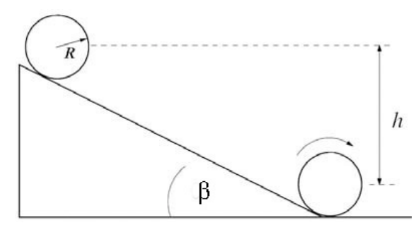
Example 20.2 Cylinder Rolling Without Slipping Down an Inclined Plane
A uniform cylinder of outer radius R and mass M with moment of inertia about the center of mass \(I_{\mathrm{cm}}=(1 / 2) M R^{2}\) starts from rest and rolls without slipping down an incline tilted at an angle β from the horizontal. The center of mass of the cylinder has dropped a vertical distance h when it reaches the bottom of the incline. Let g denote the gravitational constant. What is the relation between the component of the acceleration of the center of mass in the direction down the inclined plane and the component of the angular acceleration into the page of Figure 20.11?
Solution: We begin by choosing a coordinate system for the translational and rotational motion as shown in Figure 20.12.
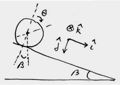
For a time interval \(\Delta t\) the displacement of the center of mass is given by \(\Delta \overrightarrow{\mathbf{R}}_{c m}(t)=\Delta X_{c m} \hat{\mathbf{i}}\) The arc length due to the angular displacement of a point on the rim during the time interval \(\Delta t\) is given by \(\Delta s=R \Delta \theta\). The rolling without slipping condition is
\[\Delta X_{c m}=R \Delta \theta \nonumber \]
If we divide both sides by \(\Delta t\) and take the limit as \(\Delta t \rightarrow 0\) then the rolling without slipping condition show that the x -component of the center of mass velocity is equal to the magnitude of the tangential component of the velocity of a point on the rim
\[V_{\mathrm{cm}}=\lim _{\Delta t \rightarrow 0} \frac{\Delta X_{\mathrm{cm}}}{\Delta t}=\lim _{\Delta t \rightarrow 0} R \frac{\Delta \theta}{\Delta t}=R \omega_{\mathrm{cm}} \nonumber \]
Similarly if we differentiate both sides of the above equation, we find a relation between the x -component of the center of mass acceleration is equal to the magnitude of the tangential component of the acceleration of a point on the rim
\[A_{\mathrm{cm}}=\frac{d V_{\mathrm{cm}}}{d t}=R \frac{d \omega_{\mathrm{cm}}}{d t}=R \alpha_{\mathrm{cm}} \nonumber \]
Example 20.3 Falling Yo-Yo
A Yo-Yo of mass m has an axle of radius b and a spool of radius R (Figure 20.13a). Its moment of inertia about the center of mass can be taken to be \(I=(1 / 2) m R^{2}\) (the thickness of the string can be neglected). The Yo-Yo is released from rest. What is the relation between the angular acceleration about the center of mass and the linear acceleration of the center of mass?

Consider a point on the rim of the axle at a distance \(r=b\) from the center of mass. As the yo-yo falls, the arc length \(\Delta s=b \Delta \theta\) subtended by the rotation of this point is equal to length of string that has unraveled, an amount \(\Delta l\). In a time interval \(\Delta t, b \Delta \theta=\Delta l\). Therefore, \(b \Delta \theta / \Delta t=\Delta l / \Delta t\).Taking limits, noting that, \(V_{\mathrm{cm}, y}=d l / d t\) we have that \(b \omega_{\mathrm{cm}}=V_{\mathrm{cm}, y}\) Differentiating a second time yields \(b \alpha_{\mathrm{cm}}=A_{\mathrm{cm}, y}\).
Example 20.4 Unwinding Drum
Drum A of mass m and radius R is suspended from a drum B also of mass m and radius R , which is free to rotate about its axis. The suspension is in the form of a massless metal tape wound around the outside of each drum, and free to unwind (Figure 20.14). Gravity acts with acceleration g downwards. Both drums are initially at rest. Find the initial acceleration of drum A , assuming that it moves straight down.
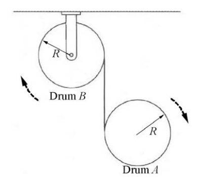
Solution: The key to solving this problem is to determine the relation between the three kinematic quantities \(\alpha_{A}, \alpha_{B}, \text { and } a_{A}\) the angular accelerations of the two drums and the linear acceleration of drum A . Choose the positive y -axis pointing downward with the origin at the center of drum B . After a time interval \(\Delta t\) the center of drum A has undergone a displacement \(\Delta y\). An amount of tape \(\Delta l_{A}=R \Delta \theta_{A}\) has unraveled from drum A , and an amount of tape \(\Delta l_{B}=R \Delta \theta_{B}\) has unraveled from drum B . Therefore the displacement of the center of drum A is equal to the total amount of tape that has unwound from the two drums, \(\Delta y=\Delta l_{A}+\Delta l_{B}=R \Delta \theta_{A}+R \Delta \theta_{B}\). Dividing through by \(\Delta t\) and taking the limit as \(\Delta t \rightarrow 0\) yields
\[\frac{d y}{d t}=R \frac{d \theta_{A}}{d t}+R \frac{d \theta_{B}}{d t} \nonumber \]
Differentiating a second time yields the desired relation between the angular accelerations of the two drums and the linear acceleration of drum A ,
\[\begin{array}{c}
\frac{d^{2} y}{d t^{2}}=R \frac{d^{2} \theta_{A}}{d t^{2}}+R \frac{d^{2} \theta_{B}}{d t^{2}} \\
a_{A, y}=R \alpha_{A}+R \alpha_{B}
\end{array} \nonumber \]