
21.6: Worked Examples
- Page ID
- 25646

Example 21.1 Angular Impulse
Two point-like objects are located at the points A and B, of respective masses \(M_{A}=2 M, \text { and } M_{B}=M\) as shown in the figure below. The two objects are initially oriented along the y-axis and connected by a rod of negligible mass of length D , forming a rigid body. A force of magnitude \(F=|\overrightarrow{\mathbf{F}}|\) along the x direction is applied to the object at B at t = 0 for a short time interval Δt , (Figure 21.3). Neglect gravity. Give all your answers in terms of M and D as needed. What is the magnitude of the angular velocity of the system after the collision?
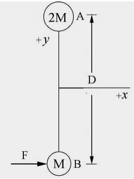
Solutions: An impulse of magnitude \(F \Delta t\) is applied in the +x direction, and the center of mass of the system will move in this direction. The two masses will rotate about the center of mass, counterclockwise in the figure. Before the force is applied we can calculate the position of the center of mass (Figure 21.4a),
\[\overrightarrow{\mathbf{R}}_{\mathrm{cm}}=\frac{M_{A} \overrightarrow{\mathbf{r}}_{A}+M_{B} \overrightarrow{\mathbf{r}}_{B}}{M_{A}+M_{B}}=\frac{2 M(D / 2) \hat{\mathbf{j}}+M(D / 2)(-\hat{\mathbf{j}})}{3 M}=(D / 6) \hat{\mathbf{j}} \nonumber \]
The center of mass is a distance (2 / 3)D from the object at B and is a distance (1/ 3)D from the object at A.

Because \(F \Delta t \hat{\mathbf{i}}=3 M \overrightarrow{\mathbf{V}}_{\mathrm{cm}}\), the magnitude of the velocity of the center of mass is then \(F \Delta t / 3 \mathrm{M}\) and the direction is in the positive \(\hat{\mathbf{i}}\) -direction. Because the force is applied at the point B, there is no torque about the point B, hence the angular momentum is constant about the point B. The initial angular momentum about the point B is zero. The angular momentum about the point B (Figure 21.4b) after the impulse is applied is the sum of two terms,
\[\begin{array}{l}
\overrightarrow{\mathbf{0}}=\overrightarrow{\mathbf{L}}_{B, f}=\overrightarrow{\mathbf{r}}_{B, f} \times 3 M \overrightarrow{\mathbf{V}}_{\mathrm{cm}}+\overrightarrow{\mathbf{L}}_{\mathrm{cm}}=(2 D / 3) \hat{\mathbf{j}} \times F \Delta t \hat{\mathbf{i}}+\overrightarrow{\mathbf{L}}_{\mathrm{cm}} \\
\overrightarrow{\mathbf{0}}=(2 D F \Delta t / 3)(-\hat{\mathbf{k}})+\overrightarrow{\mathbf{L}}_{\mathrm{cm}}
\end{array} \nonumber \]
The angular momentum about the center of mass is given by
\[\overrightarrow{\mathbf{L}}_{c m}=I_{c m} \omega \hat{\mathbf{k}}=\left(2 M(D / 3)^{2}+M(2 D / 3)^{2}\right) \omega \hat{\mathbf{k}}=(2 / 3) M D^{2} \omega \hat{\mathbf{k}} \nonumber \]
Thus the angular about the point B after the impulse is applied is
\[\overrightarrow{\mathbf{0}}=(2 D F \Delta t / 3)(-\hat{\mathbf{k}})+(2 / 3) M D^{2} \omega \hat{\mathbf{k}} \nonumber \]
We can solve this Equation (21.6.4) for the angular speed
\[\omega=\frac{F \Delta t}{M D} \nonumber \]
Example 21.2 Person on a railroad car moving in a circle
A person of mass M is standing on a railroad car, which is rounding an unbanked turn of radius R at a speed \(v\). His center of mass is at a height of L above the car midway between his feet, which are separated by a distance of \(d\). The man is facing the direction of motion (Figure 21.5). What is the magnitude of the normal force on each foot?

Solution: We begin by choosing a cylindrical coordinate system and drawing a free-body force diagram, shown in Figure 21.6.

We decompose the contact force between the inner foot closer to the center of the circular motion and the ground into a tangential component corresponding to static friction \(\overrightarrow{\mathbf{f}}_{1}\) and a perpendicular component, \(\overrightarrow{\mathbf{N}}_{1}\) In a similar fashion we decompose the contact force between the outer foot further from the center of the circular motion and the ground into a tangential component corresponding to static friction \(\overrightarrow{\mathbf{f}}_{2}\) and a perpendicular component, \(\overrightarrow{\mathbf{N}}_{2}\). We do not assume that the static friction has its maximum magnitude nor do we assume that \(\overrightarrow{\mathbf{f}}_{1}=\overrightarrow{\mathbf{f}}_{2} \text { or } \overrightarrow{\mathbf{N}}_{1}=\overrightarrow{\mathbf{N}}_{2}\). The gravitational force acts at the center of mass.
We shall use our two dynamical equations of motion, Equation (21.4.1) for translational motion and Equation (21.4.4) for rotational motion about the center of mass noting that we are considering the special case that \(\overrightarrow{\boldsymbol{\alpha}}_{c m}=0\) because the object is not rotating about the center of mass. In order to apply Equation (21.4.1), we treat the person as a point-like particle located at the center of mass and all the external forces act at this point. The radial component of Newton’s Second Law (Equation (21.4.1) is given by
\[\hat{\mathbf{r}}:-f_{1}-f_{2}=-m \frac{v^{2}}{R} \nonumber \]
The vertical component of Newton’s Second Law is given by
\[\hat{\mathbf{k}}: N_{1}+N_{2}-m g=0 \nonumber \]
The rotational equation of motion (Equation (21.4.4) is
\[\vec{\tau}_{\mathrm{cm}}^{\mathrm{total}}=0 \nonumber \]
We begin our calculation of the torques about the center of mass by noting that the gravitational force does not contribute to the torque because it is acting at the center of mass. We draw a torque diagram in Figure 21.7a showing the location of the point of application of the forces, the point we are computing the torque about (which in this case is the center of mass), and the vector \(\overrightarrow{\mathbf{r}}_{\mathrm{cm}, 1}\) from the point we are computing the torque about to the point of application of the forces.

The torque on the inner foot is given by
\[\vec{\tau}_{\mathrm{cm}, 1}=\overrightarrow{\mathrm{r}}_{\mathrm{cm}, 1} \times\left(\overrightarrow{\mathrm{f}}_{1}+\overrightarrow{\mathrm{N}}_{1}\right)=\left(-\frac{d}{2} \hat{\mathbf{r}}-L \hat{\mathbf{k}}\right) \times\left(-f_{1} \hat{\mathbf{r}}+N_{1} \hat{\mathbf{k}}\right)=\left(\frac{d}{2} N_{1}+L f_{1}\right) \hat{\boldsymbol{\theta}} \nonumber \]
We draw a similar torque diagram (Figure 21.7b) for the forces applied to the outer foot. The torque on the outer foot is given by
\[\vec{\tau}_{\mathrm{cm}, 2}=\overrightarrow{\mathrm{r}}_{\mathrm{cm}, 2} \times\left(\overrightarrow{\mathrm{f}}_{2}+\overrightarrow{\mathrm{N}}_{2}\right)=\left(+\frac{d}{2} \hat{\mathbf{r}}-L \hat{\mathbf{k}}\right) \times\left(-f_{2} \hat{\mathbf{r}}+N_{2} \hat{\mathbf{k}}\right)=\left(-\frac{d}{2} N_{2}+L f_{2}\right) \hat{\boldsymbol{\theta}} \nonumber \]
Notice that the forces \(\overrightarrow{\mathbf{f}}_{1}, \overrightarrow{\mathbf{N}}_{1}, \text { and } \overrightarrow{\mathbf{f}}_{2}\) all contribute torques about the center of mass in the positive \(\hat{\boldsymbol{\theta}}\)-direction while \(\overrightarrow{\mathbf{N}}_{2}\) contributes a torque about the center of mass in the negative \(\hat{\boldsymbol{\theta}}\)-direction According to Equation (21.6.8) the sum of these torques about the center of mass must be zero. Therefore
\[\begin{aligned}
\vec{\tau}_{\mathrm{cm}}^{\operatorname{ext}} &=\vec{\tau}_{\mathrm{cm}, 1}+\vec{\tau}_{\mathrm{cm}, 2}=\left(\frac{d}{2} N_{1}+L f_{1}\right) \hat{\boldsymbol{\theta}}+\left(-\frac{d}{2} N_{2}+L f_{2}\right) \hat{\boldsymbol{\theta}} \\
&=\left(\frac{d}{2}\left(N_{1}-N_{2}\right)+L\left(f_{1}+f_{2}\right)\right) \hat{\boldsymbol{\theta}}=\overrightarrow{\mathbf{0}}
\end{aligned} \nonumber \]
Notice that the magnitudes of the two frictional forces appear together as a sum in Equations (21.6.11) and (21.6.6). We now can solve Equation (21.6.6) for \(f_{1}+f_{2}\) and substitute the result into Equation (21.6.11) yielding the condition that
\[\frac{d}{2}\left(N_{1}-N_{2}\right)+L m \frac{v^{2}}{R}=0 \nonumber \]
We can rewrite this Equation as
\[N_{2}-N_{1}=\frac{2 L m v^{2}}{R d} \nonumber \]
We also rewrite Equation (21.6.7) in the form
\[N_{2}+N_{1}=m g \nonumber \]
We now can solve for \(N_{2}\) by adding together Equations (21.6.13) and (21.6.14), and then divide by two,
\[N_{2}=\frac{1}{2}\left(M g+\frac{2 L m v^{2}}{R d}\right) \nonumber \]
We now can solve for \(N_{1}\) by subtracting Equations (21.6.13) from (21.6.14), and then divide by two,
\[N_{1}=\frac{1}{2}\left(m g-\frac{2 L m v^{2}}{R d}\right) \nonumber \]
Check the result: we see that the normal force acting on the outer foot is greater in magnitude than the normal force acting on the inner foot. We expect this result because as we increase the speed v , we find that at a maximum speed \(v_{\max }\) the normal force on the inner foot goes to zero and we start to rotate in the positive \(\hat{\boldsymbol{\theta}}\)- direction tipping outward. We can find this maximum speed by setting N1 = 0 in Equation (21.6.16) resulting in
\[v_{\max }=\sqrt{\frac{g R d}{2 L}} \nonumber \]
Example 21.3 Torque, Rotation and Translation: Yo-Yo
A Yo-Yo of mass m has an axle of radius b and a spool of radius R . Its moment of inertia about the center can be taken to be \(I_{c m}=(1 / 2) m R^{2}\) and the thickness of the string can be neglected (Figure 21.8). The Yo-Yo is released from rest. You will need to assume that the center of mass of the Yo-Yo descends vertically, and that the string is vertical as it unwinds. (a) What is the tension in the cord as the Yo-Yo descends? (b) What is the magnitude of the angular acceleration as the yo-yo descends and the magnitude of the linear acceleration? (c) Find the magnitude of the angular velocity of the Yo-Yo when it reaches the bottom of the string, when a length l of the string has unwound.

Solutions: a) as the Yo-Yo descends it rotates clockwise in Figure 21.9. The torque about the center of mass of the Yo-Yo is due to the tension and increases the magnitude of the angular velocity. The direction of the torque is into the page in Figure 21.9 (positive z - direction). Use the right-hand rule to check this, or use the vector product definition of torque,
\[\vec{\tau}_{\mathrm{cm}}=\overrightarrow{\mathbf{r}}_{\mathrm{cm}, T} \times \overrightarrow{\mathbf{T}} \nonumber \]
About the center of mass, \(\overrightarrow{\mathbf{r}}_{\mathrm{cm}, T}=-b \hat{\mathbf{i}} \text { and } \overrightarrow{\mathbf{T}}=-T \hat{\mathbf{j}}\) so the torque is
\[\vec{\tau}_{\mathrm{cm}}=\overrightarrow{\mathbf{r}}_{\mathrm{cm}, T} \times \overrightarrow{\mathbf{T}}=(-b \hat{\mathbf{i}}) \times(-T \hat{\mathbf{j}})=b T \hat{\mathbf{k}} \nonumber \]
Apply Newton’s Second Law in the ˆ j-direction,
\[m g-T=m a_{y} \nonumber \]
Apply the rotational equation of motion for the Yo-Yo,
\[b T=I_{\mathrm{cm}} \alpha_{z} \nonumber \]
where \(\alpha_{z}\) is the z -component of the angular acceleration. The z -component of the angular acceleration and the y -component of the linear acceleration are related by the constraint condition
\[a_{y}=b \alpha_{z} \nonumber \]
where b is the axle radius of the Yo-Yo. Substitute Equation (21.6.22) into (21.6.20) yielding
\[m g-T=m b \alpha_{z} \nonumber \]
Now solve Equation (21.6.21) for \(\alpha_{z}\) and substitute the result into Equation(21.6.23),
\[m g-T=\frac{m b^{2} T}{I_{\mathrm{cm}}} \nonumber \]
Solve Equation (21.6.24) for the tension T ,
\[T=\frac{m g}{\left(1+\frac{m b^{2}}{I_{\mathrm{cm}}}\right)}=\frac{m g}{\left(1+\frac{m b^{2}}{(1 / 2) m R^{2}}\right)}=\frac{m g}{\left(1+\frac{2 b^{2}}{R^{2}}\right)} \nonumber \]
b) Substitute Equation (21.6.25) into Equation (21.6.21) to determine the z -component of the angular acceleration,
\[\alpha_{z}=\frac{b T}{I_{\mathrm{cm}}}=\frac{2 b g}{\left(R^{2}+2 b^{2}\right)} \nonumber \]
Using the constraint condition Equation (21.6.22), we determine the y -component of linear acceleration
\[a_{y}=b \alpha_{z}=\frac{2 b^{2} g}{\left(R^{2}+2 b^{2}\right)}=\frac{g}{1+R^{2} / 2 b^{2}} \nonumber \]
Note that both quantities \(a_{z}>0 \text { and } \alpha_{z}>0\) so Equations (21.6.26) and (21.6.27) are the magnitudes of the respective quantities. For a typical Yo-Yo, the acceleration is much less than that of an object in free fall.
c) Use conservation of energy to determine the magnitude of the angular velocity of the Yo-Yo when it reaches the bottom of the string. As in Figure 21.9, choose the downward vertical direction as the positive \(\hat{\mathbf{j}}\)-direction and let y = 0 designate the location of the center of mass of the Yo-Yo when the string is completely wound. Choose U ( y = 0) = 0 for the zero reference potential energy. This choice of direction and reference means that the gravitational potential energy will be negative and decreasing while the Yo-Yo descends. For this case, the gravitational potential energy is
\[U=-m g y \nonumber \]
The Yo-Yo is not yet moving downward or rotating, and the center of mass is located at y = 0 so the mechanical energy in the initial state, when the Yo-Yo is completely wound, is zero
\[E_{i}=U(y=0)=0 \nonumber \]
Denote the linear speed of the Yo-Yo as \(v_{f}\) and its angular speed as \(\omega_{f}\) (at the point y = l ). The constraint condition between \(v_{f}\) and \(\omega_{f}\) is given by
\[v_{f}=b \omega_{f} \nonumber \]
consistent with Equation (21.6.22). The kinetic energy is the sum of translational and rotational kinetic energy, where we have used \(I_{\mathrm{cm}}=(1 / 2) m R^{2}\) and so mechanical energy in the final state, when the Yo-Yo is completely unwound, is
\[\begin{aligned}
E_{f} &=K_{f}+U_{f}=\frac{1}{2} m v_{f}^{2}+\frac{1}{2} I_{\mathrm{cm}} \omega_{f}^{2}-m g l \\
&=\frac{1}{2} m b^{2} \omega_{f}^{2}+\frac{1}{4} m R^{2} \omega_{f}^{2}-m g l
\end{aligned} \nonumber \]
There are no external forces doing work on the system (neglect air resistance), so
\[0=E_{f}=E_{i} \nonumber \]
Thus
\[\left(\frac{1}{2} m b^{2}+\frac{1}{4} m R^{2}\right) \omega_{f}^{2}=m g l \nonumber \]
Solving for \(\omega_{f}\)
\[\omega_{f}=\sqrt{\frac{4 g l}{\left(2 b^{2}+R^{2}\right)}} \nonumber \]
We may also use kinematics to determine the final angular velocity by solving for the time interval Δt that it takes for the Yo-Yo to travel a distance l at the constant acceleration found in Equation (21.6.27)),
\[\Delta t=\sqrt{2 l / a_{y}}=\sqrt{\frac{l\left(R^{2}+2 b^{2}\right)}{b^{2} g}} \nonumber \]
The final angular velocity of the Yo-Yo is then (using Equation (21.6.26) for the z -component of the angular acceleration),
\[\omega_{f}=\alpha_{z} \Delta t=\sqrt{\frac{4 g l}{\left(R^{2}+2 b^{2}\right)}} \nonumber \]
in agreement with Equation (21.6.34).
Example 21.4 Cylinder Rolling Down Inclined Plane
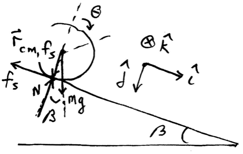
A uniform cylinder of outer radius R and mass M with moment of inertia about the center of mass, \(I_{\mathrm{cm}}=(1 / 2) M R^{2}\) starts from rest and rolls without slipping down an incline tilted at an angle \(\beta\) from the horizontal. The center of mass of the cylinder has dropped a vertical distance h when it reaches the bottom of the incline Figure 21.10. Let g denote the gravitational constant. The coefficient of static friction between the cylinder and the surface is \(\mu_{\mathrm{s}}\). What is the magnitude of the velocity of the center of mass of the cylinder when it reaches the bottom of the incline?

Solution: We shall solve this problem three different ways.
1. Apply the torque condition about the center of mass and the force law for the center of mass motion.
2. Apply the energy methods.
3. Use torque about a fixed point that lies along the line of contact between the cylinder and the surface,
First Approach: Rotation about center of mass and translation of center of mass
We shall apply the torque condition (Equation (21.4.4)) about the center of mass and the force law (Equation (21.4.1)) for the center of mass motion. We will first find the acceleration and hence the speed at the bottom of the incline using kinematics. The forces are shown in Figure 21.11.
Choose x = 0 at the point where the cylinder just starts to roll. Newton’s Second Law, applied in the x - and y -directions in turn, yields
\[\begin{array}{l}
M g \sin \beta-f_{s}=M a_{x} \\
-N+M g \cos \beta=0
\end{array} \nonumber \]
Choose the center of the cylinder to compute the torque about (Figure 21.10). Then, the only force exerting a torque about the center of mass is the friction force, therefore the rotational equation of motion is
\[f_{s} R=I_{\mathrm{cm}} \alpha_{z} \nonumber \]
Use \(I_{\mathrm{cm}}=(1 / 2) M R^{2}\) and the kinematic constraint for the no-slipping condition \(\alpha_{z}=a_{x} / R\) in Equation (21.6.39) to solve for the magnitude of the static friction force yielding
\[f_{s}=(1 / 2) M a_{x} \nonumber \]
Substituting Equation (21.6.40) into Equation (21.6.37) yields
\[M g \sin \theta-(1 / 2) M a_{x}=M a_{x} \nonumber \]
which we can solve for the acceleration
\[a_{x}=\frac{2}{3} g \sin \beta \nonumber \]
In the time \(t_{f}\) it takes to reach the bottom, the displacement of the cylinder is \(x_{f}=h / \sin \beta\). The x -component of the velocity \(v_{x}\) at the bottom is \(v_{x, f}=a_{x} t_{f}\). Thus \(x_{f}=(1 / 2) a_{x} t_{f}^{2}\). After eliminating \(t_{f}\), we have \(x_{f}=v_{x, f}^{2} / 2 a_{x}\) so the x -component of the velocity when the cylinder reaches the bottom of the inclined plane is
\[v_{x, f}=\sqrt{2 a_{x} x_{f}}=\sqrt{2((2 / 3) g \sin \beta)(h / \sin \beta)}=\sqrt{(4 / 3) g h} \nonumber \]
Note that if we substitute Equation (21.6.42) into Equation (21.6.40) the magnitude of the frictional force is
\[f_{s}=(1 / 3) M g \sin \beta \nonumber \]
In order for the cylinder to roll without slipping
\[f_{s} \leq \mu_{s} M g \cos \beta \nonumber \]
Combining Equation (21.6.44) and Equation (21.6.45) we have the condition that
\[(1 / 3) M g \sin \beta \leq \mu_{s} M g \cos \beta \nonumber \]
Thus in order to roll without slipping, the coefficient of static friction must satisfy
\[\mu_{\mathrm{s}} \geq \frac{1}{3} \tan \beta \nonumber \]
Second Approach: Energy Methods
We shall use the fact that the energy of the cylinder-earth system is constant since the static friction force does no work.

Choose a zero reference point for potential energy at the center of mass when the cylinder reaches the bottom of the incline plane (Figure 21.12). Then the initial potential energy is
\[U_{i}=M g h \nonumber \]
For the given moment of inertia, the final kinetic energy is
\[\begin{aligned}
K_{\mathrm{f}} &=\frac{1}{2} M v_{x, f}^{2}+\frac{1}{2} I_{\mathrm{cm}} \omega_{z, f}^{2} \\
&=\frac{1}{2} M v_{x, f}^{2}+\frac{1}{2}(1 / 2) M R^{2}\left(v_{x, f} / R\right)^{2} \\
&=\frac{3}{4} M v_{x, f}^{2}
\end{aligned} \nonumber \]
Setting the final kinetic energy equal to the initial gravitational potential energy leads to
\[M g h=\frac{3}{4} M v_{x, f}^{2} \nonumber \]
The magnitude of the velocity of the center of mass of the cylinder when it reaches the bottom of the incline is
\[v_{x, f}=\sqrt{(4 / 3) g h} \nonumber \]
in agreement with Equation (21.6.43).
Third Approach: Torque about a fixed point that lies along the line of contact between the cylinder and the surface

The gravitational force \(M \overrightarrow{\mathbf{g}}=M g \sin \beta \hat{\mathbf{i}}+M g \cos \beta \hat{\mathbf{j}}\) acts at the center of mass. The vector from the point P to the center of mass is given by \(\overrightarrow{\mathbf{r}}_{P, m g}=d_{P} \hat{\mathbf{i}}-R \hat{\mathbf{j}}\) so the torque due to the gravitational force about the point P is given by
\[\begin{array}{l}
\overrightarrow{\mathbf{\tau}}_{P, M g}=\overrightarrow{\mathbf{r}}_{P, M g} \times M \overrightarrow{\mathbf{g}}=\left(d_{P} \hat{\mathbf{i}}-R \hat{\mathbf{j}}\right) \times(M g \sin \beta \hat{\mathbf{i}}+M g \cos \beta \hat{\mathbf{j}}) \\
=\left(d_{P} M g \cos \beta+R M g \sin \beta\right) \hat{\mathbf{k}}
\end{array} \nonumber \]
The normal force acts at the point of contact between the cylinder and the surface and is given by \(\overrightarrow{\mathbf{N}}=-N \hat{\mathbf{j}}\) The vector from the point P to the point of contact between the cylinder and the surface is \(\overrightarrow{\mathbf{r}}_{P, N}=d_{P} \hat{\mathbf{i}}\) Therefore the torque due to the normal force about the point P is given by
\[\vec{\tau}_{P, N}=\overrightarrow{\mathbf{r}}_{P, N} \times \overrightarrow{\mathbf{N}}=\left(d_{P} \hat{\mathbf{i}}\right) \times(-N \hat{\mathbf{j}})=-d_{P} N \hat{\mathbf{k}} \nonumber \]
Substituting Equation (21.6.38) for the normal force into Equation (21.6.53) yields
\[\overrightarrow{\boldsymbol{\tau}}_{P, N}=-d_{P} M g \cos \beta \hat{\mathbf{k}} \nonumber \]
Therefore the sum of the torques about the point P is
\[\overrightarrow{\boldsymbol{\tau}}_{P}=\overrightarrow{\boldsymbol{\tau}}_{P, M g}+\overrightarrow{\boldsymbol{\tau}}_{P, N}=\left(d_{P} M g \cos \beta+R M g \sin \beta\right) \hat{\mathbf{k}}-d_{P} M g \cos \beta \hat{\mathbf{k}}=R m g \sin \beta \hat{\mathbf{k}} \hat{\mathbf{k}} \nonumber \]
The angular momentum about the point P is given by
\[\begin{aligned}
\overrightarrow{\mathbf{L}}_{P} &=\overrightarrow{\mathbf{L}}_{\mathrm{cm}}+\overrightarrow{\mathbf{r}}_{P, \mathrm{cm}} \times M \overrightarrow{\mathbf{V}}_{c m}=I_{\mathrm{cm}} \omega_{z} \hat{\mathbf{k}}+\left(d_{P} \hat{\mathbf{i}}-R \hat{\mathbf{j}}\right) \times\left(M v_{x}\right) \hat{\mathbf{i}} \\
&=\left(I_{\mathrm{cm}} \omega_{z}+R M v_{x}\right) \hat{\mathbf{k}}
\end{aligned} \nonumber \]
The time derivative of the angular momentum about the point P is then
\[\frac{d \overrightarrow{\mathbf{L}}_{P}}{d t}=\left(I_{\mathrm{cm}} \alpha_{z}+R M a_{x}\right) \hat{\mathbf{k}} \nonumber \]
Therefore the torque law about the point P , becomes
\[R M g \sin \beta \hat{\mathbf{k}}=\left(I_{\mathrm{cm}} \alpha_{z}+R M a_{x}\right) \hat{\mathbf{k}} \nonumber \]
Using the fact that \(I_{\mathrm{cm}}=(1 / 2) M R^{2}\) and \(\alpha_{x}=a_{x} / R\) the z -component of Equation (21.6.58) is then
\[R M g \sin \beta=(1 / 2) M R a_{x}+R m a_{x}=(3 / 2) M R a_{x} \nonumber \]
We can now solve Equation (21.6.59) for the x -component of the acceleration
\[a_{x}=(2 / 3) g \sin \beta \nonumber \]
in agreement with Equation (21.6.42).
Example 21.5 Bowling Ball
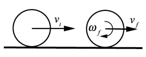
A bowling ball of mass m and radius R is initially thrown down an alley with an initial speed \(v_{i}\), and it slides without rolling but due to friction it begins to roll (Figure 21.14). The moment of inertia of the ball about its center of mass is \(I_{\mathrm{cm}}=(2 / 5) m R^{2}\). Using conservation of angular momentum about a point (you need to find that point), find the speed \(v_{f}\) and the angular speed \(\omega_{f}\) of the bowling ball when it just starts to roll without slipping?
Solution: We begin introducing coordinates for the angular and linear motion. Choose an angular coordinate θ increasing in the clockwise direction. Choose the positive kˆ unit vector pointing into the page in Figure 21.15.
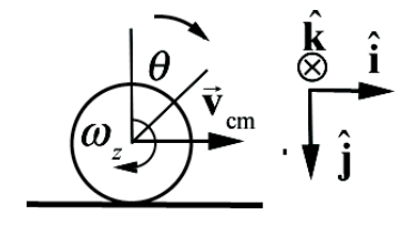
Then the angular velocity vector is \(\overrightarrow{\boldsymbol{\omega}}=\omega_{z} \hat{\mathbf{k}}=d \theta / d t \hat{\mathbf{k}}\) and the angular acceleration vector is \(\overrightarrow{\boldsymbol{\alpha}}=\alpha_{z} \hat{\mathbf{k}}=d^{2} \theta / d t^{2} \hat{\mathbf{k}}\). Choose the positive \(\hat{\mathbf{i}}\) unit vector pointing to the right in Figure 21.15. Then the velocity of the center of mass is given by \(\overrightarrow{\mathbf{v}}_{\mathrm{cm}}=v_{\mathrm{cm}, x} \hat{\mathbf{i}}=d x_{\mathrm{cm}} / d t \hat{\mathbf{i}}\) and the acceleration of the center of mass is given by \(\overrightarrow{\mathbf{a}}_{\mathrm{cm}}=a_{\mathrm{cm}, x} \hat{\mathbf{i}}=d^{2} x_{\mathrm{cm}} / d t^{2} \hat{\mathbf{i}}\). The free-body force diagram is shown in Figure 21.16.

At t = 0 , when the ball is released, \(\overrightarrow{\mathbf{v}}_{c m, 0}=v_{0} \hat{\mathbf{i}}\) and \(\vec{\omega}_{0}=\overrightarrow{0}\) so the ball is skidding and hence the frictional force on the ball due to the sliding of the ball on the surface is kinetic friction, hence acts in the negative \(\hat{\mathbf{i}}\)-direction. Because there is kinetic friction and nonconservative work, mechanical energy is not constant. The rotational equation of motion is \(\overrightarrow{\boldsymbol{\tau}}_{S}=d \overrightarrow{\mathbf{L}}_{S} / d t\). In order for angular momentum about some point to remain constant \(S\) throughout the motion, the torque about that point must also be zero throughout the motion. As the ball moves down the alley, the contact point will move, but the frictional force will always be directed along the line of contact between the bowling bowl and the surface. Choose any fixed point \(S\) along the line of contact then
\begin{equation}\vec{\tau}_{S, f_{k}}=\overrightarrow{\mathbf{r}}_{S, f_{k}} \times \overrightarrow{\mathbf{f}}_{k}=\overrightarrow{\mathbf{0}}\end{equation}
because \(\overrightarrow{\mathbf{r}}_{S, f_{k}}\) and \(\overrightarrow{\mathbf{f}}_{k}\) are anti-parallel. The gravitation force acts at the center of mass hence the torque due to gravity about \(S\) is
\begin{equation}\vec{\tau}_{S, m g}=\overrightarrow{\mathbf{r}}_{S, m g} \times m \overrightarrow{\mathbf{g}}=d m g \hat{\mathbf{k}}\end{equation}
where d is the distance from \(S\) to the contact point between the ball and the ground. The torque due to the normal force about \(S\) is
\begin{equation}\vec{\tau}_{S, N}=\overrightarrow{\mathbf{r}}_{S, N} \times m \overrightarrow{\mathrm{g}}=-d N \hat{\mathbf{k}}\end{equation}
with the same moment arm d. Because the ball is not accelerating in the \(\hat{\mathbf{j}}\)-direction, from Newton’s Second Law, we note that \(m g-N=0\). Therefore
\begin{equation}\vec{\tau}_{S, N}+\vec{\tau}_{S, m g}=d(m g-N) \hat{\mathbf{k}}=\overrightarrow{\mathbf{0}}\end{equation}
There is no torque about any fixed point \(S\) along the line of contact between the bowling bowl and the surface; therefore the angular momentum about that point \(S\) is constant,
\[\overrightarrow{\mathbf{L}}_{S, i}=\overrightarrow{\mathbf{L}}_{S, f} \nonumber \]
Choose one fixed point \(S\) along the line of contact (Figure 21.17).

The initial angular momentum about \(S\) is only due to the translation of the center of mass (Figure 21.17a),
\[\overrightarrow{\mathbf{L}}_{s, i}=\overrightarrow{\mathbf{r}}_{S, \mathrm{cm}, i} \times m \overrightarrow{\mathbf{v}}_{\mathrm{cm}, i}=m R v_{\mathrm{cm}, i} \hat{\mathbf{k}} \nonumber \]
In Figure 21.17b, the ball is rolling without slipping. The final angular momentum about \(S\) has both a translational and rotational contribution
\[\overrightarrow{\mathbf{L}}_{S, f}=\overrightarrow{\mathbf{r}}_{S, \mathrm{cm}, f} \times m \overrightarrow{\mathbf{v}}_{\mathrm{cm}, f}+I_{c m} \overrightarrow{\boldsymbol{\omega}}_{f}=m R v_{\mathrm{cm}, f} \hat{\mathbf{k}}+I_{\mathrm{cm}} \omega_{z, f} \hat{\mathbf{k}} \nonumber \]
When the ball is rolling without slipping, \(v_{\mathrm{cm}, f}=R \omega_{z, f}\) and also \(I_{\mathrm{cm}}=(2 / 5) m R^{2}\). Therefore the final angular momentum about \(S\) is
\[\overrightarrow{\mathbf{L}}_{s, f}=(m R+(2 / 5) m R) v_{\mathrm{cm}, f} \hat{\mathbf{k}}=(7 / 5) m R v_{\mathrm{cm}, f} \hat{\mathbf{k}} \nonumber \]
Equating the z -components in Equations (21.6.66) and (21.6.68) yields
\[m R v_{\mathrm{cm}, i}=(7 / 5) m R v_{\mathrm{cm}, f} \nonumber \]
which we can solve for
\[v_{\mathrm{cm}, f}=(5 / 7) v_{c m, i} \nonumber \]
The final angular velocity vector is
\[\overrightarrow{\boldsymbol{\omega}}=\omega_{z, f} \hat{\mathbf{k}}=\frac{v_{\mathrm{cm}, f}}{R} \hat{\mathbf{k}}=\frac{5 v_{\mathrm{cm}, i}}{7 R} \hat{\mathbf{k}} \nonumber \]
We could also solve this problem by analyzing the translational motion and the rotational motion about the center of mass. Gravity exerts no torque about the center of mass, and the normal component of the contact force has a zero moment arm; the only force that exerts a torque is the frictional force, with a moment arm of R (the force vector and the radius vector are perpendicular). The frictional force should be in the negative x - direction. From the right-hand rule, the direction of the torque is into the page, and hence in the positive z -direction. Equating the z -component of the torque to the rate of change of angular momentum about the center of mass yields
\[\tau_{c m}=R f_{k}=I_{c m} \alpha_{z} \nonumber \]
where \(f_{k}\) is the magnitude of the kinetic frictional force and \(\alpha_{z_{z}}\) is the z -component of the angular acceleration of the bowling ball. Note that Equation (21.6.72) results in a positive z -component of the angular acceleration, which is consistent with the ball tending to rotate as indicated Figure 21.15. The frictional force is also the only force in the horizontal direction, and will cause an acceleration of the center of mass,
\[a_{c m, x}=-f_{k} / m \nonumber \]
Note that the x -component of the acceleration will be negative, as expected. Now we need to consider the kinematics. The bowling ball will increase its z -component of the angular velocity as given in Equation (21.6.72) and decrease its x -component of the velocity as given in Equation (21.6.73),
\[\begin{aligned}
\omega_{z}(t) &=\alpha_{z} t=\frac{R f_{k}}{I_{\mathrm{cm}}} t \\
v_{\mathrm{cm}, x}(t) &=v_{\mathrm{cm}, i}-\frac{f_{k}}{m} t
\end{aligned} \nonumber \]
As soon as the ball stops slipping, the kinetic friction no longer acts, static friction is zero, and the ball moves with constant angular and linear velocity. Denote the time when this happens as \(t_{f}\) At this time the rolling without slipping condition, \(\omega_{z}\left(t_{f}\right)=v_{\mathrm{cm}, x}\left(t_{f}\right) / R\), holds and the relations in Equation (21.6.74) become
\[\begin{array}{c}
R^{2} \frac{f_{k}}{I_{c m}} t_{f}=v_{\mathrm{cm}, x, f} \\
v_{\mathrm{cm}, x, i}-\frac{f_{k}}{m} t_{f}=v_{\mathrm{cm}, x, f}
\end{array} \nonumber \]
We can now solve the first equation in Equation (21.6.75) for \(t_{f}\) and find that
\[t_{f}=\frac{I_{\mathrm{cm}}}{f_{k} R^{2}} v_{\mathrm{cm}, x, f} \nonumber \]
We now substitute Equation (21.6.76) into the second equation in Equation (21.6.75) and find that
\[\begin{array}{l}
v_{\mathrm{cm}, x, f}=v_{\mathrm{cm}, x, i}-\frac{f_{k}}{m} \frac{I_{\mathrm{cm}}}{f_{k} R^{2}} v_{\mathrm{cm}, x, f} \\
v_{\mathrm{cm}, x, f}=v_{\mathrm{cm}, x, i}-\frac{I_{\mathrm{cm}}}{m R^{2}} v_{\mathrm{cm}, x, f}
\end{array} \nonumber \]
The second equation in (21.6.77) is easily solved for
\[v_{\mathrm{cm}, x, f}=\frac{v_{0}}{1+I_{\mathrm{cm}} / m R^{2}}=\frac{5}{7} v_{\mathrm{cm}, x, i} \nonumber \]
agreeing with Equation (21.6.70) where we have used \(I_{\mathrm{cm}}=(2 / 5) m R^{2}\) for a uniform sphere.
Example 21.6 Rotation and Translation Object and Stick Collision
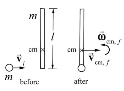
A long narrow uniform stick of length l and mass m lies motionless on ice (assume the ice provides a frictionless surface). The center of mass of the stick is the same as the geometric center (at the midpoint of the stick). The moment of inertia of the stick about its center of mass is \(I_{\mathrm{cm}}\) A puck (with putty on one side) has the same mass m as the stick. The puck slides without spinning on the ice with a velocity of \(\overrightarrow{\mathbf{v}}_{i}\) toward the stick, hits one end of the stick, and attaches to it (Figure 21.18). You may assume that the radius of the puck is much less than the length of the stick so that the moment of inertia of the puck about its center of mass is negligible compared to \(I_{\mathrm{cm}}\) (a) How far from the midpoint of the stick is the center of mass of the stick-puck combination after the collision? (b) What is the linear velocity \(\overrightarrow{\mathbf{V}}_{\mathrm{cm}, f}\) of the stick plus puck after the collision? (c) Is mechanical energy conserved during the collision? Explain your reasoning. (d) What is the angular velocity \(\overrightarrow{\boldsymbol{\omega}}_{\mathrm{cm}, f}\) of the stick plus puck after the collision? (e) How far does the stick's center of mass move during one rotation of the stick?
Solution: In this problem we will calculate the center of mass of the puck-stick system after the collision. There are no external forces or torques acting on this system so the momentum of the center of mass is constant before and after the collision and the angular momentum about the center of mass of the puck-stick system is constant before and after the collision. We shall use these relations to compute the final angular velocity of the puck-stick about the center of mass.

a) With respect to the center of the stick, the center of mass of the stick-puck combination is
\begin{equation}d_{\mathrm{cm}}=\frac{m_{\text {sick }} d_{\text {sick }}+m_{\text {puck }} d_{\text {puck }}}{m_{\text {sick }}+m_{\text {puck }}}=\frac{m(l / 2)}{m+m}=\frac{l}{4}\end{equation}
where we are neglecting the radius of the puck (Figure 21.19).
b) During the collision, the only net forces on the system (the stick-puck combination) are the internal forces between the stick and the puck (transmitted through the putty). Hence, the linear momentum is constant. Initially only the puck had linear momentum \(\overrightarrow{\mathbf{p}}_{i}=m \overrightarrow{\mathbf{v}}_{i}=m v_{i} \hat{\mathbf{i}}\). After the collision, the center of mass of the system is moving with velocity \(\overrightarrow{\mathbf{v}}_{\mathrm{cm}, f}=v_{\mathrm{cm}, f} \hat{\mathbf{i}}\) Equating initial and final linear momenta,
\begin{equation}m v_{i}=(2 m) v_{\mathrm{cm}, f} \Rightarrow v_{\mathrm{cm}, f}=\frac{v_{i}}{2}\end{equation}
The direction of the velocity is the same as the initial direction of the puck’s velocity.
c) The forces that deform the putty do negative work (the putty is compressed somewhat), and so mechanical energy is not conserved; the collision is totally inelastic.
d) Choose the center of mass of the stick-puck combination, as found in part a), as the point \(S\) about which to find angular momentum. This choice means that after the collision there is no angular momentum due to the translation of the center of mass. Before the collision, the angular momentum was entirely due to the motion of the puck,
\[\overrightarrow{\mathbf{L}}_{S, i}=\overrightarrow{\mathbf{r}}_{\text {puck }} \times \overrightarrow{\mathbf{p}}_{i}=(l / 4)\left(m v_{i}\right) \hat{\mathbf{k}} \nonumber \]
where \(\hat{\mathbf{k}}\) is directed out of the page in Figure 21.19. After the collision, the angular momentum is
\[\overrightarrow{\mathbf{L}}_{S, f}=I_{\mathrm{cm}, f} \omega_{c m, f} \hat{\mathbf{k}} \nonumber \]
where \(I_{\mathrm{cm}, f}\) is the moment of inertia about the center of mass of the stick-puck combination. This moment of inertia of the stick about the new center of mass is found from the parallel axis theorem and the moment of inertia of the puck, which is \(m(l / 4)^{2}\). Therefore
\[I_{\mathrm{cm}, f}=I_{\mathrm{cm}, \text { stick }}+I_{\mathrm{cm}, \text { puck }}=\left(I_{\mathrm{cm}}+m(l / 4)^{2}\right)+m(l / 4)^{2}=I_{\mathrm{cm}}+\frac{m l^{2}}{8} \nonumber \]
Inserting this expression into Equation (21.6.82), equating the expressions for \(\overrightarrow{\mathbf{L}}_{S, i}\) and \(\overrightarrow{\mathbf{L}}_{S, f}\) and solving for \(\omega_{\mathrm{cm}, f}\) yeilds
\[\omega_{\mathrm{cm}, f}=\frac{m(l / 4)}{I_{\mathrm{cm}}+m l^{2} / 8} v_{i} \nonumber \]
If the stick is uniform, \(I_{\mathrm{cm}}=m l^{2} / 12\) and Equation (21.6.84) reduces to
\[\omega_{\mathrm{cm}, f}=\frac{6}{5} \frac{v_{i}}{l} \nonumber \]
It may be tempting to try to calculate angular momentum about the contact point C , where the putty hits the stick. If this is done, there is no initial angular momentum, and after the collision the angular momentum will be the sum of two parts, the angular momentum of the center of mass of the stick and the angular moment about the center of the stick,
\[\overrightarrow{\mathbf{L}}_{C, f}=\overrightarrow{\mathbf{r}}_{\mathrm{cm}} \times \overrightarrow{\mathbf{p}}_{\mathrm{cm}}+I_{\mathrm{cm}} \overrightarrow{\boldsymbol{\omega}}_{\mathrm{cm}, f} \nonumber \]
There are two crucial things to note: First, the speed of the center of mass is not the speed found in part b); the rotation must be included, so that \(v_{\mathrm{cm}}=v_{i} / 2-\omega_{\mathrm{cm}, f}(l / 4)\). Second, the direction of \(\overrightarrow{\mathbf{r}}_{\mathrm{cm}} \times \overrightarrow{\mathbf{p}}_{\mathrm{cm}}\) with respect to the contact point C is, from the right-hand rule, into the page, or the \(-\hat{\mathbf{k}}\)-direction, opposite the direction of \(\overrightarrow{\boldsymbol{\omega}}_{\mathrm{cm}, f}\) This is to be expected, as the sum in Equation (21.6.86) must be zero. Adding the \(\hat{\mathbf{k}}\)-components (the only components) in Equation (21.6.86),
\(-(l / 2) m\left(v_{i} / 2-\omega_{\mathrm{cm}, f}(l / 4)\right)+I_{\mathrm{cm}} \omega_{\mathrm{cm}, f}=0\)
Solving Equation (21.6.87) for \(\omega_{\mathrm{cm}, f}\) yields Equation (21.6.84).
This alternative derivation should serve two purposes. One is that it doesn’t matter which point we use to find angular momentum. The second is that use of foresight, in this case choosing the center of mass of the system so that the final velocity does not contribute to the angular momentum, can prevent extra calculation. It’s often a matter of trial and error (“learning by misadventure”) to find the “best” way to solve a problem.
e) The time of one rotation will be the same for all observers, independent of choice of origin. This fact is crucial in solving problems, in that the angular velocity will be the same (this was used in the alternate derivation for part d) above). The time for one rotation is the period \(T=2 \pi / \omega_{f}\) and the distance the center of mass moves is
\[\begin{aligned}
x_{\mathrm{cm}} &=v_{\mathrm{cm}} T=2 \pi \frac{v_{\mathrm{cm}}}{\omega_{\mathrm{cm}, f}} \\
&=2 \pi \frac{v_{i} / 2}{\left(\frac{m(l / 4)}{I_{\mathrm{cm}}+m l^{2} / 8}\right) v_{i}} \\
&=2 \pi \frac{I_{\mathrm{cm}}+m l^{2} / 8}{m(l / 2)}
\end{aligned} \nonumber \]
Using \(I_{\mathrm{cm}}=m l^{2} / 12\) for a uniform stick gives
\[x_{\mathrm{cm}}=\frac{5}{6} \pi l \nonumber \]