
22.3: Why Does a Gyroscope Precess?
- Page ID
- 25673

Why does a gyroscope precess? We now understand that the torque is causing the spin angular momentum to change but the motion still seems mysterious. We shall try to understand why the angular momentum changes direction by first examining the role of force and impulse on a single rotating particle and then generalize to a rotating disk.
Deflection of a Particle by a Small Impulse
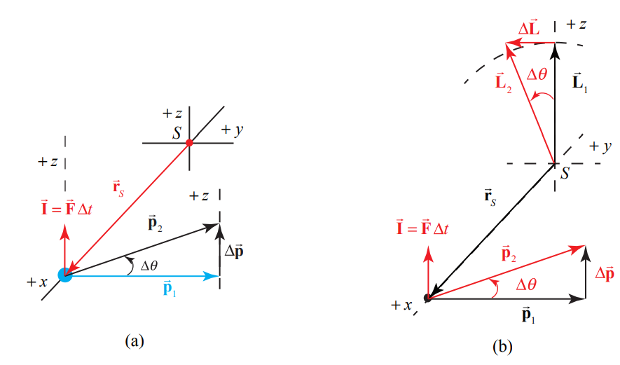
We begin by first considering how a particle with momentum \(\overrightarrow{\mathbf{p}}_{1}\) undergoes a deflection due to a small impulse (Figure 22.9a). If the impulse \(|\overrightarrow{\mathbf{I}}|<\left\langle\overrightarrow{\mathbf{p}}_{1}\right|\), the primary effect is to rotate the momentum \(\overrightarrow{\mathbf{p}}_{1}\) about the x -axis by a small angle θ , with \(\overrightarrow{\mathbf{p}}_{2}=\overrightarrow{\mathbf{p}}_{1}+\Delta \overrightarrow{\mathbf{p}}\). The application of \(\overrightarrow{\mathbf{I}}\) causes a change in the angular momentum \(\overrightarrow{\mathbf{L}}_{O, 1}\) about the origin \(S\), according to the torque equation, \(\Delta \overrightarrow{\mathbf{L}}_{s}=\overrightarrow{\mathfrak{\tau}}_{\text {ave }, s} \Delta t=\left(\overrightarrow{\mathbf{r}}_{s} \times \overrightarrow{\mathbf{F}}_{\text {ave }}\right) \Delta t\). Because \(\overrightarrow{\mathbf{I}}=\Delta \overrightarrow{\mathbf{p}}=\overrightarrow{\mathbf{F}}_{\mathrm{ave}} \Delta t\) we have that \(\Delta \overrightarrow{\mathbf{L}}_{s}=\overrightarrow{\mathbf{r}}_{s} \times \overrightarrow{\mathbf{I}}\). As a result, \(\Delta \overrightarrow{\mathbf{L}}_{s}\) rotates about the x -axis by a small angle θ , to a new angular momentum \(\overrightarrow{\mathbf{L}}_{s, 2}=\overrightarrow{\mathbf{L}}_{s, 1}+\Delta \overrightarrow{\mathbf{L}}_{s}\). Note that although \(\overrightarrow{\mathbf{L}}_{s}\) is in the z -direction, \(\Delta \overrightarrow{\mathbf{L}}_{s}\) is in the negative y-direction (Figure 22.9b).
Effect of Small Impulse on Tethered Object

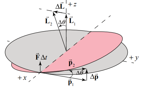
Now consider an object that is attached to a string and is rotating about a fixed point \(S\) with momentum \(\overrightarrow{\mathbf{p}}_{1}\). The object is given an impulse \(\overline{\mathbf{I}}\) perpendicular to \(\overrightarrow{\mathbf{r}}_{S}\) and to \(\overrightarrow{\mathbf{p}}_{1}\). Neglect gravity. As a result \(\Delta \overrightarrow{\mathbf{L}}_{s}\) rotates about the x -axis by a small angle θ (Figure 22.10a). Note that although \(\overrightarrow{\mathbf{I}}\) is in the z -direction, \(\Delta \overrightarrow{\mathbf{L}}_{s}\) is in the negative y - direction (Figure 22.10b). Note that although \(\overline{\mathbf{I}}\) is in the z -direction, the plane in which the ball moves also rotates about the x -axis by the same angle (Figure 22.11).
Example 22.2 Effect of Large Impulse on Tethered Object

What impulse, \(\overline{\mathbf{I}}\) must be given to the ball in order to rotate its orbit by 90 degrees as shown without changing its speed (Figure 21.12)?
Solution: h. The impulse \(\overrightarrow{\mathbf{I}}\) must halt the momentum \(\overrightarrow{\mathbf{p}}_{1}\) and provide a momentum \(\overrightarrow{\mathbf{p}}_{2}\) of equal magnitude along the z -direction such that \(\overrightarrow{\mathbf{I}}=\Delta \overrightarrow{\mathbf{p}}\).
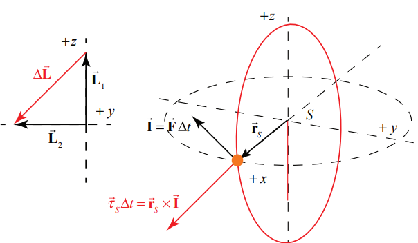
The angular impulse about \(S\) must be equal to the change in angular momentum about S
\[\vec{\tau}_{S} \Delta t=\vec{r}_{S} \times \vec{I}=\left(\vec{r}_{S} \times \Delta \vec{p}\right)=\Delta \vec{L}_{S} \nonumber \]
The change in angular momentum, \(\Delta \overrightarrow{\mathbf{L}}_{s}\) due to the torque about \(S\), cancels the z -component of \(\overrightarrow{\mathbf{L}}_{s}\) and adds a component of the same magnitude in the negative y -direction (Figure 22.13).
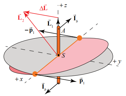
Effect of Small Impulse Couple on Baton

Now consider two equal masses at the ends of a massless rod, which spins about its center. We apply an impulse couple to insure no motion of the center of mass. Again note that the impulse couple is applied in the z -direction (Figure 22.14a). The resulting torque about \(S\) lies along the negative y -direction and the plane of rotation tilts about the x -axis (Figure 22.14b).
Effect of Small Impulse Couple on Massless Shaft of Baton
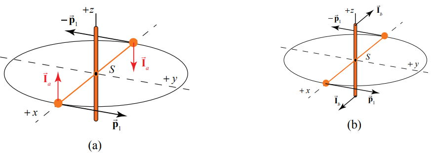
Instead of applying the impulse couple \(\overrightarrow{\mathbf{I}}_{a}\) to the masses (Figure 21.15a), one could apply the same impulse couple \(\overrightarrow{\mathbf{I}}_{b}=\overrightarrow{\mathbf{I}}_{a}\) to the vertical massless shaft that is connected to the baton (Figure 22.15b) to achieve the same result.
Twisting the shaft around the y -axis causes the shaft and the plane in which the baton moves to rotate about the x -axis.
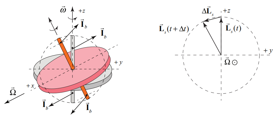
Effect of a Small Impulse Couple on a Rotating Disk

Now let’s consider a rotating disk. The plane of a rotating disk and its shaft behave just like the plane of the rotating baton and its shaft when one attempts to twist the shaft about the y -axis. The plane of the disk rotates about the x -axis (Figure 22.17). This unexpected result is due to the large pre-existing angular momentum about S, \(\overrightarrow{\mathbf{L}}_{1}\) due to the spinning disk. It does not matter where along the shaft the impulse couple is applied, as long as it creates the same torque about \(S\).
Effect of a Force Couple on a Rotating Disk
A series of small impulse couples, or equivalently a continuous force couple (with force \(\overrightarrow{\mathbf{F}}\) causes the tip of the shaft to execute circular motion about the x -axis (Figure 22.18). The magnitude of the angular momentum about \(S\) changes according to \(\left|d \overrightarrow{\mathbf{L}}_{s}\right|=\left|\overrightarrow{\mathbf{L}}_{s}\right| \Omega d t=I \omega \Omega d t\). Recall that torque and changing angular momentum about \(S\) are related by \(\overrightarrow{\boldsymbol{\tau}}_{S}=d \overrightarrow{\mathbf{L}}_{S} / d t\). Therefore, \(\left|\vec{\tau}_{s}\right|=\left|\overrightarrow{\mathbf{L}}_{s}\right| \Omega=I \omega \Omega\) The precession rate of the shaft is the ratio of the magnitude of the torque to the angular momentum \(\Omega=\left|\vec{\tau}_{s}\right| /\left|\overrightarrow{\mathbf{L}}_{s}\right|=\left|\vec{\tau}_{s}\right| / I \omega\).
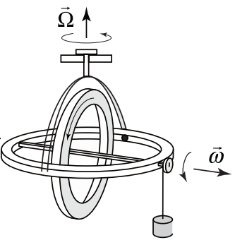
Thus we can explain the motion of a precessing gyroscope in which the torque about the center of mass is provided by the force of gravity on the hanging object (Figure 22.19).
Effect of a Small Impulse Couple on a Non-Rotating Disc
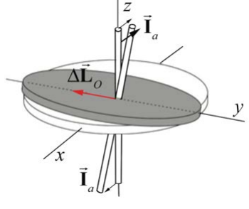
If the disk is not rotating to begin with, \(\Delta \overrightarrow{\mathbf{L}}_{s}\) is also the final \(\overrightarrow{\mathbf{L}}_{S}\). The shaft moves in the direction it is pushed (Figure 22.20).