
13.20: Torque-free rotation of an inertially-symmetric rigid rotor
- Page ID
- 30807

Euler's equations of motion
There are many situations where one has rigid-body motion free of external torques, that is, \(\mathbf{N} = 0\). The tumbling motion of a jugglers baton, a diver, a rotating galaxy, or a frisbee, are examples of rigid-body rotation. For torque-free rotation, the body will rotate about the center of mass, and thus the inertia tensor with respect to the center of mass is required. An inertially-symmetric rigid body has two identical principal moments of inertia with \(I_1 = I_2 \neq I_3\), and provides a simple example that illustrates the underlying motion. The force-free Euler equations for the symmetric body in the body-fixed principal axis system are given by
\[ \begin{align} (I_2 − I_3) \omega_2\omega_3 − I_1\dot{\omega}_1 &= 0 \label{13.111} \\[4pt] (I_3 − I_1) \omega_3\omega_1 − I_2\dot{\omega}_2 &= 0 \label{13.112} \\[4pt] I_3\dot{\omega}_3 &= 0 \label{13.113} \end{align}\]
where \(I_1 = I_2\) and \(N = 0\) apply.
Note that for torque-free motion of an inertially symmetric body Equation \ref{13.113} implies that \(\dot{\omega}_3 = 0\), i.e. \(\omega_3\) is a constant of motion and thus is a cyclic variable for the symmetric rigid body.
Equations \ref{13.111} and \ref{13.112} can be written as two coupled equations
\[\dot{\omega}_1 + \Omega \omega_2 = 0 \label{13.114}\]
\[\dot{\omega}_2 − \Omega \omega_1 = 0 \label{13.115}\]
where the precession angular velocity \(\mathbf{\Omega} = \dot{\psi}\) with respect to the body-fixed frame is defined to be
\[\mathbf{\Omega} \equiv \left( \frac{(I_3 − I_1)}{I_1} \boldsymbol{\omega}_3 \right) \label{13.116}\]
Combining the time derivatives of equations \ref{13.114} and \ref{13.115} leads to two uncoupled equations
\[\ddot{\omega}_1 + \Omega^2 \omega_1 = 0 \]
\[ \ddot{\omega}_2 + \Omega^2 \omega_2 = 0 \]
These are the differential equations for a harmonic oscillator with solutions
\[\omega_1 = A \cos \Omega t\]
\[\omega_2 = A \sin \Omega t\]
These equations describe a vector \(A\) rotating in a circle of radius \(A\) about an axis perpendicular to \(\hat{e}_3\), that is, rotating in the \(\hat{e}_1 − \hat{e}_2\) plane with angular frequency \(\Omega = −\dot{\psi}\). Note that
\[\omega^2_1 + \omega^2_2 = A^2 \label{13.120}\]
which is a constant. In addition \(\omega_3\) is constant, therefore the magnitude of the total angular velocity
\[|\boldsymbol{\omega} | = \sqrt{ \omega^2_1 + \omega^2_2 + \omega^2_3 }= \text{ constant} \label{13.121}\]
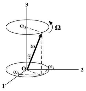
The motion of the torque-free symmetric body is that the angular velocity \(\boldsymbol{\omega}\) precesses around the symmetry axis \(\hat{e}_3\) of the body at an angle \(\alpha\) with a constant precession frequency \(\Omega\) with respect to the body-fixed frame as shown in Figure \(\PageIndex{1}\). Thus, to an observer on the body, \(\boldsymbol{\omega}\) traces out a cone around the body-fixed symmetry axis. Note from \ref{13.116} that the vectors \(\Omega \hat{e}_3\) and \(\omega_3\hat{e}_3\) are parallel when \(\Omega\) is positive, that is, \(I_3 > I\) (oblate shape) and antiparallel if \(I_3 < I\) (prolate shape).
For the system considered, the orientation of the angular momentum vector \(\mathbf{L}\) must be stationary in the space-fixed inertial frame since the system is torque free, that is, \(\mathbf{L}\) is a constant of motion. Also we have that the projection of the angular momentum on the body-fixed symmetry axis is a constant of motion, that is, it is a cyclic variable. Thus
\[L_3 = I_3 \omega_3 = \frac{I_1I_3}{(I_3 − I_1)} \Omega \]
Understanding the relation between the angular momentum and angular velocity is facilitated by considering another constant of motion for the torque-free symmetric rotor, namely the rotational kinetic energy.
\[T_{rot} = \frac{1}{2} \boldsymbol{\omega} \cdot \mathbf{L} = \text{ constant} \]
Since \(\mathbf{L}\) is a constant for torque-free motion, and also the magnitude of \(\boldsymbol{\omega}\) was shown to be constant, therefore the angle between these two vectors must be a constant to ensure that also \(T_{\mathbf{rot}} = \frac{1}{2}\boldsymbol{\omega} \cdot \mathbf{L} = \) constant. That is, \(\mathbf{\omega}\) precesses around \(\mathbf{L}\) at a constant angle \((\theta − \alpha )\) such that the projection of \(\boldsymbol{\omega}\) onto \(\mathbf{L}\) is constant. Note that
\[\boldsymbol{\omega} \times \widehat{\mathbf{e}_3} = \omega_2 \widehat{\mathbf{e}_1} − \omega_1\widehat{\mathbf{e}_2} \]
and, for a symmetric rotor,
\[\mathbf{L} \cdot \boldsymbol{\omega} \times \widehat{\mathbf{e}_3} = I_1\omega_1\omega_2 − I_2\omega_1\omega_2 = 0 \]
since \(I_1 = I_2\) for the symmetric rotor. Because \(\mathbf{L} \cdot \boldsymbol{\omega} \times \widehat{\mathbf{e}_3} = 0\) for a symmetric top then \(\mathbf{L}\), \(\boldsymbol{\omega}\) and \(\widehat{\mathbf{e}_3}\) are coplanar.
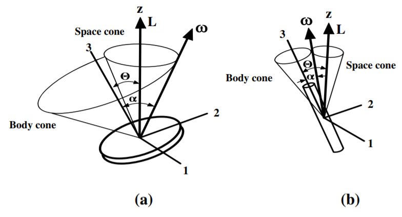
Figure \(\PageIndex{2}\) shows the geometry of the motion for both oblate and prolate axially-deformed bodies. To an observer in the space-fixed inertial frame, the angular velocity \(\boldsymbol{\omega}\) traces out a cone that precesses with angular velocity \(\Omega\) around the space fixed \(\mathbf{L}\) axis called the space cone. For convenience, Figure \(\PageIndex{2}\) assumes that \(\mathbf{L}\) and the space-fixed inertial frame \(\hat{\mathbf{z}}\) axis are colinear. The angular velocity \(\boldsymbol{\omega}\) also traces out the body cone as it precesses about the body-fixed \(\hat{\mathbf{e}}_3\) axis. Since \(\mathbf{L}\), \(\boldsymbol{\omega}\) and \(\widehat{\mathbf{e}_3}\) are coplanar, then the \(\boldsymbol{\omega}\) vector is at the intersection of the space and body cones as the body cone rolls around the space cone. That is, the space and body cones have one generatrix in common which coincides with \(\boldsymbol{\omega}\). As shown in Figure \(\PageIndex{2b}\), for a needle the body cone appears to roll without slipping on the outside of the space cone at the precessional velocity of \(\Omega = −\omega\). By contrast, as shown in Figure \(\PageIndex{2a}\) for an oblate (disc-shaped) symmetric top the space cone rolls inside the body cone and the precession \(\Omega\) is faster than \(\omega\).
Since no external torques are acting for torque-free motion, then the magnitude and direction of the total angular momentum are conserved. The description of the motion is simplified if \(\mathbf{L}\) is taken to be along the space-fixed \(\hat{\mathbf{z}}\) axis, then the Euler angle \(\theta\) is the angle between the body-fixed basis vector \(\hat{\mathbf{e}}_3\) and space-fixed basis vector \(\hat{\mathbf{z}}\). If at some instant in the body frame, it is assumed that \(\widehat{\mathbf{e}_2}\) is aligned in the plane of \(\mathbf{L}\), \(\boldsymbol{\omega}\) and \(\widehat{\mathbf{e}_3}\), then
\[L_1 = 0 \quad L_2 = L \sin \theta \quad L_3 = L\cos \theta \label{13.126}\]
If \(\alpha\) is the angle between the angular velocity \(\boldsymbol{\omega}\) and the body-fixed \(\hat{\mathbf{e}}_3\) axis, then at the same instant
\[\omega_1 = 0 \quad \omega_2 = \omega \sin \alpha \quad \omega_3 = \omega \cos \alpha \label{12.127}\]
The components of the angular momentum also can be derived from \(\mathbf{L} = \mathbf{I} \cdot \boldsymbol{\omega}\) to give
\[L_1 = I_1\omega_1 = 0 \quad L_2 = I_2 \omega_2 = I_1\omega \sin \alpha \quad L_3 = I_3\omega_3 = I_3\omega \cos \alpha \label{13.128}\]
Equations \ref{13.126} and \ref{13.128} give two relations for the ratio \(\frac{L_2}{L_3}\), that is,
\[\frac{L_2}{L_3} = \tan \theta = \frac{I_1}{I_3} \tan \alpha \label{13.129}\]
For a prolate spheroid \(I_1 > I_3\) therefore \(\theta > \alpha\) while \(\Omega\) and \(\omega_3\) have opposite signs.
For a oblate spheroid \(I_1 < I_3\) therefore \(\alpha > \theta\) while \(\Omega\) and \(\omega_3\) have the same sign.
The sense of precession can be understood if the body cone rolls without slipping on the outside of the space cone with \(\Omega\) in the opposite orientation to \(\omega\) for the prolate case, while for the oblate case the space cone rolls inside the body cone with \(\Omega\) and \(\omega\) oriented in similar directions. Note from \ref{13.129} that \(\theta = 0\) if \(\alpha = 0\), that is \(\mathbf{L}\), \(\boldsymbol{\omega}\) and the \(\mathbf{3}\) axis are aligned corresponding to a principal axis. Similarly, \(\theta = 90^{\circ}\) if \(\alpha = 90^{\circ}\), then again \(\mathbf{L}\) and \(\boldsymbol{\omega}\) are aligned corresponding to them being principal axes.
Lagrangian mechanics has been used to calculate the motion with respect to the body-fixed principal axis system. However, the motion needs to be known relative to the space-fixed inertial frame where the motion is observed. This transformation can be done using the following relation
\[\left(\frac{d \hat{\mathbf{e}}_3}{dt}\right)_{space} = \left(\frac{d\hat{\mathbf{e}}_3}{dt} \right)_{body} + \boldsymbol{\omega} \times \hat{\mathbf{e}}_3 = \boldsymbol{\omega} \times \hat{\mathbf{e}}_3 \]
since the unit vector \(\hat{\mathbf{e}}_3\) is stationary in the body-fixed frame. The vector product of \(\boldsymbol{\omega} \times \hat{\mathbf{e}}_3\) and \(\hat{\mathbf{e}}_3\) gives
\[\begin{align*} \hat{\mathbf{e}}_3 \times \left(\frac{d\hat{\mathbf{e}}_3}{dt}\right)_{space} &= \hat{\mathbf{e}}_3 \times \boldsymbol{\omega} \times \hat{\mathbf{e}}_3 \\[4pt] &= (\hat{\mathbf{e}}_3 \cdot \hat{\mathbf{e}}_3) \boldsymbol{\omega} − (\hat{\mathbf{e}}_3 \cdot \boldsymbol{\omega} ) \hat{\mathbf{e}}_3 = \boldsymbol{\omega} − \omega_3 \hat{\mathbf{e}}_3 \end{align*}\]
therefore
\[\boldsymbol{\omega} = \hat{\mathbf{e}}_3 \times \left(\frac{d\hat{\mathbf{e}}_3}{dt}\right)_{space} + \omega_3\hat{\mathbf{e}}_3 \label{13.131}\]
The angular momentum equals \(\mathbf{L} = \{\mathbf{I}\} \cdot \boldsymbol{\omega}\). Since \(\hat{\mathbf{e}}_3 \times \left(\frac{d\hat{\mathbf{e}}_3}{dt}\right)_{space} \) is perpendicular to the \(\hat{\mathbf{e}}_3\) axis, then for the case with \(I_1 = I_2\),
\[\mathbf{L} =I_1\hat{\mathbf{e}}_3 \times \left(\frac{d\hat{\mathbf{e}}_3}{dt}\right)_{space} + I_3\omega_3\hat{\mathbf{e}}_3 \label{13.132}\]
Thus the angular momentum for a torque-free symmetric rigid rotor comprises two components, one being the perpendicular component that precesses around \(\hat{\mathbf{e}}_3\), and the other is \(L_3\).
In the space-fixed frame assume that the \(\hat{\mathbf{z}}\) axis is colinear with \(\mathbf{L}\). Then taking the scalar product of \(\hat{\mathbf{e}}_3\) and \(\mathbf{L}\), using Equation \ref{13.126} gives
\[\begin{align} L_3 &= \hat{\mathbf{e}}_3 \cdot \mathbf{L} \\[4pt] &=I_1\hat{\mathbf{e}}_3 \cdot \hat{\mathbf{e}}_3 \times \left(\frac{d\hat{\mathbf{e}}_3}{dt}\right)_{space} + I_3\omega_3\hat{\mathbf{e}}_3 \cdot \hat{\mathbf{e}}_3 \label{13.133}\end{align}\]
The first term on the right is zero and thus Equation \ref{13.133} and \ref{13.126} give
\[L_3 = I_3\omega_3 = L \cos \theta \]
The time dependence of the rotation of the body-fixed symmetry axis with respect to the space-fixed axis system can be obtained by taking the vector product \(\hat{\mathbf{e}}_3 \times \mathbf{L}\) using Equation \ref{13.132} and using equation \(B.24\) to expand the triple vector product,
\[\begin{align} \hat{\mathbf{e}}_3 \times \mathbf{L} &= I_1\hat{\mathbf{e}}_3 \times \left( \hat{\mathbf{e}}_3 \times \left(\frac{d\hat{\mathbf{e}}_3}{dt}\right)_{space}\right) + I_3\omega_3\hat{\mathbf{e}}_3 \times \hat{\mathbf{e}}_3 \label{13.135} \\[4pt] \notag &= I_1 \left[\left( \hat{\mathbf{e}}_3 \cdot \left(\frac{d\hat{\mathbf{e}}_3}{dt}\right)_{space} \right) \hat{\mathbf{e}}_3 − (\hat{\mathbf{e}}_3 \cdot \hat{\mathbf{e}}_3) \left(\frac{d\hat{\mathbf{e}}_3}{dt}\right)_{space}\right] + 0 \end{align}\]
since \((\hat{\mathbf{e}}_3 \times \hat{\mathbf{e}}_3)=0\). Moreover \((\hat{\mathbf{e}}_3 \cdot \hat{\mathbf{e}}_3)=1\), and \(\hat{\mathbf{e}}_3 \cdot \left(\frac{d\hat{\mathbf{e}}_3}{dt}\right)_{space}= 0\), since they are perpendicular, then
\[\left(\frac{d\hat{\mathbf{e}}_3}{dt}\right)_{space} = \frac{\mathbf{L}}{I_1} \times \hat{\mathbf{e}}_3 \label{13.136}\]
This equation shows that the body-fixed symmetry axis \(\hat{\mathbf{e}}_3\) precesses around the \(\mathbf{L}\), where \(\mathbf{L}\) is a constant of motion for torque-free rotation. The true rotational angular velocity \(\boldsymbol{\omega}\) in the space-fixed frame, given by equations \ref{13.131}, can be evaluated using Equation \ref{13.136}. Remembering that it was assumed that \(\mathbf{L}\) is in the \(\hat{\mathbf{z}}\) direction, that is, \(\mathbf{L} =L\hat{\mathbf{z}}\), then
\[\begin{align} \notag \boldsymbol{\omega} &= \hat{\mathbf{e}}_3 \times \left(\frac{d\hat{\mathbf{e}}_3}{dt}\right)_{space} + \omega_3\hat{\mathbf{e}}_3 \\[4pt] \notag &= \frac{L}{I_1} \hat{\mathbf{e}}_3 \times (\hat{\mathbf{z}} \times \hat{\mathbf{e}}_3) + \left( \frac{L \cos \alpha}{ I_3} \right) \hat{\mathbf{e}}_3 \\[4pt] &= \frac{L}{ I_1} \hat{\mathbf{z}} + L \cos \alpha \left( \frac{I_1 − I_3}{ I_1I_3}\right) \hat{\mathbf{e}}_3 \end{align}\]
That is, the symmetry axis of the axially-symmetric rigid rotor makes an angle \(\theta\) to the angular momentum vector \(L\hat{\mathbf{z}}\) and precesses around \(L\hat{\mathbf{z}}\) with a constant angular velocity \(\frac{L}{I_1}\) while the axial spin of the rigid body has a constant value \(\frac{L}{I_3}\). Thus, in the precessing frame, the rigid body appears to rotate about its fixed symmetry axis with a constant angular velocity \(\frac{L \cos \alpha}{I_3} − \frac{L \cos \alpha}{I_1} = L \cos \alpha \left(\frac{I_1−I_3}{I_1 I_3}\right)\). The precession of the symmetry axis looks like a wobble superimposed on the spinning motion about the body-fixed symmetry axis. The angular precession rate in the space-fixed frame can be deduced by using the fact that
\[\dot{\phi} \sin \theta = \omega \sin \alpha \label{13.138}\]
Then using Equation \ref{13.129} allows Equation \ref{13.138} to be written as
\[\dot{\phi} = \omega \sqrt{\left[ 1 + \left(\left(\frac{I_3}{I_1}\right)^2 -1 \right) \cos^2 \alpha \right] }\]
which gives the precession rate about the space-fixed axis in terms of the angular velocity \(\omega \). Note that the precession rate \(\dot{\phi} > \omega\) if \(\frac{I_3}{I_1} > 1\), that is, for oblate shapes, and \(\dot{\phi} < \omega\) if \(\frac{I_3}{I_1} < 1\), that is, for prolate shapes.
Lagrange equations of motion
It is interesting to compare the equations of motion for torque-free rotation of an inertially-symmetric rigid rotor derived using Lagrange mechanics with that derived previously using Euler’s equations based on Newtonian mechanics. Assume that the principal moments about the fixed point of the symmetric top are \(I_1 = I_2 \neq I_3\) and that the kinetic energy equals the rotational kinetic energy, that is, it is assumed that the translational kinetic energy \(T_{trans} = 0\). Then the kinetic energy is given by
\[T =\frac{1}{2} \sum_i I_i \omega^2_i =\frac{1}{2}I_1 ( \omega^2_1 + \omega^2_2 ) +\frac{1}{2}I_3\omega^2_3 \]
Equations \((13.14.1-13.14.3)\) for the body-fixed frame give
\[\omega^2_1 = \left( \dot{\phi} \sin \theta \sin\psi + \dot{\theta} \cos \psi \right)^2 = \dot{\phi}^2 \sin^2 \theta \sin^2 \psi + 2 \phi \dot{\theta} \sin \theta \sin\psi \cos \psi + \dot{\theta}^2 \cos^2 \psi \]
\[\omega^2_2 = \left( \dot{\phi} \sin \theta \cos \psi − \dot{\theta} \sin\psi \right)^2 = \dot{\phi}^2 \sin^2 \theta \cos^2 \psi − 2\phi \dot{\theta} \sin \theta \sin\psi \cos \psi + \dot{\theta}^2 \sin^2 \psi \]
Therefore
\[\omega^2_1 + \omega^2_2 = \dot{\phi}^2 \sin^2 \theta + \dot{\theta}^2 \]
and
\[\omega^2_3 = \left( \dot{\phi} \cos \theta + \dot{\psi} \right)^2 \]
Therefore the kinetic energy is
\[T =\frac{1}{2}I_1 \left( \dot{\phi}^2 \sin^2 \theta + \dot{\theta}^2\right) +\frac{1}{2}I_3 \left( \dot{\phi} \cos \theta + \dot{\psi} \right)^2 \]
Since the system is torque free, the scalar potential energy \(U\) can be assumed to be zero, and then the Lagrangian equals
\[L =\frac{1}{2}I_1 \left( \dot{\phi}^2 \sin^2 \theta + \dot{\theta}^2\right) +\frac{1}{2}I_3 \left( \dot{\phi} \cos \theta + \dot{\psi} \right)^2 \]
The angular momentum about the space-fixed \(z\) axis \(p_{\phi}\) is conjugate to \(\phi\). From Lagrange’s equations
\[\dot{p}_{\phi} = \frac{\partial L}{ \partial \phi } = 0 \]
that is, the angular momentum about the space-fixed \(z\) axis, \(p_{\phi}\) is a constant of motion given by
\[p_{\phi} = \frac{\partial L}{ \partial \dot{\phi}} = ( I_1 \sin^2 \theta + I_3 \cos^2 \theta ) \dot{\phi} + I_3\dot{\psi} \cos \theta = \text{ constant.}\]
Similarly, the angular momentum about the body-fixed \(3\) axis is conjugate to \(\psi\). From Lagrange’s equations
\[\dot{p}_{\psi} = \frac{\partial L}{\partial \psi } = 0 \]
that is, \(p_{\psi}\) is a constant of motion given by
\[p_{\psi} = \frac{\partial L}{ \partial \dot{\psi}} = I_3 \left( \dot{\dot{\phi}} \cos \theta + \dot{\psi} \right) = I_3\omega_3 = \text{ constant}\]
The above two relations derived from the Lagrangian can be solved to give the precession angular velocity \(\dot{\phi}\) about the space-fixed \(\hat{\mathbf{z}}\) axis
\[\dot{\phi} = \frac{p_{\phi} − p_{\psi} \cos \theta}{I_1 \sin^2 \theta} \]
and the spin about the body-fixed \(\mathbf{\hat{3}}\) axis \(\dot{\psi}\) which is given by
\[\dot{\psi} = \frac{p_{\psi}}{I_3} − \frac{(p_{\phi} − p_{\psi} \cos \theta ) \cos \theta}{ I_1 \sin^2 \theta}\]
Since \(p_{\phi}\) and \(p_{\psi}\) are constants of motion, then the precessional angular velocity \(\dot{\phi}\) about the space-fixed \(\hat{\mathbf{z}}\) axis, and the spin angular velocity \(\dot{\psi}\), which is the spin frequency about the body-fixed \(\mathbf{\hat{3}}\) axis, are constants that depend directly on \(I_1\), \(I_3\). and \(\theta\).
There is one additional constant of motion available if no dissipative forces act on the system, that is, energy conservation which implies that the total energy
\[E =\frac{1}{2}I_1 \left( \dot{\phi}^2 \sin^2 \theta + \dot{\theta}^2 \right) +\frac{1}{2}I_3 \left( \dot{\phi} \cos \theta + \dot{\psi} \right)^2 \]
will be a constant of motion. But the second term on the right-hand side also is a constant of motion since \(p_{\psi}\) and \(I_3\) both are constants, that is
\[\frac{1}{2} I_3\omega^2_3 =\frac{1}{2}I_3 \left( \dot{\phi} \cos \theta + \dot{\psi} \right)^2 = \frac{p^2_{\psi}}{I_3 } = \text{ constant}\]
Thus energy conservation implies that the first term on the right-hand side also must be a constant given by
\[\frac{1}{2} I_1 ( \omega^2_1 + \omega^2_2 ) =\frac{1}{2}I_1 \left( \dot{\phi}^2 \sin^2 \theta + \dot{\theta}^2 \right) = E - \frac{p^2_{\psi}}{I_3 } = \text{ constant }\]
These results are identical to those given in equations \ref{13.120} and \ref{13.121} which were derived using Euler’s equations. These results illustrate that the underlying physics of the torque-free rigid rotor is more easily extracted using Lagrangian mechanics rather than using the Euler-angle approach of Newtonian mechanics.
Example \(\PageIndex{1}\): Precession rate for torque-free rotating symmetric rigid rotor
Table \(\PageIndex{1}\) lists the precession and spin angular velocities, in the space-fixed frame, for torque-free rotation of three extreme symmetric-top geometries spinning with constant angular momentum \(\omega\) when the motion is slightly perturbed such that \(\omega\) is at a small angle \(\alpha\) to the symmetry axis. Note that this assumes the perpendicular axis theorem, equation \((13.9.1)\) which states that for a thin laminae \(I_1 + I_2 = I_3\) giving, for a thin circular disk, \(I_1 = I_2\) and thus \(I_3 = 2I_1\).
| Rigid-body symmetric shape | Principal moment ratio \(\frac{I_3}{I_1}\) | Precession rate \(\dot{\phi}\) | Spin rate \(\dot{\psi}\) |
|---|---|---|---|
| Symmetric needle | 0 | 0 | \(\omega\) |
| Sphere | 1 | \(\omega\) | 0 |
| Thin circular disk | 2 | \(2\omega\) | \(-\omega\) |
The precession angular velocity in the space frame ranges between 0 to \(2\omega\) depending on whether the body-fixed spin angular velocity is aligned or anti-aligned with the rotational frequency \(\omega\). For an extreme prolate spheroid \(\frac{I_3}{I_1} = 0\), the body-fixed spin angular velocity \(\Omega = −\omega_3\) which cancels the angular velocity \(\omega\) of the rotating frame resulting in a zero precession angular velocity of the body-fixed \(\hat{\mathbf{e}}_3\) axis around the space-fixed frame. The spin \(\Omega = 0\) in the body-fixed frame for the rigid sphere \(\frac{I_3}{I_1} = 1\), and thus the precession rate of the body-fixed \(\hat{e}_3\) axis of the sphere around the space-fixed frame equals \(\omega\). For oblate spheroids and thin disks, such as a frisbee, \(\frac{I_3}{I_1} = 2\) making the body-fixed precession angular velocity \(\Omega = +\omega\) which adds to the angular velocity \(\omega\) and increases the precession rate up to \(2\omega\) as seen in the space-fixed frame. This illustrates that the spin angular velocity can add constructively or destructively with the angular velocity \(\omega \).2
2In his autobiography Surely You’re Joking Mr Feynman, he wrote " I was in the [Cornell] cafeteria and some guy, fooling around, throws a plate in the air. As the plate went up in the air I saw it wobble, and noticed that the red medallion of Cornell on the plate going around. It was pretty obvious to me that the medallion went around faster than the wobbling. I started to figure out the motion of the rotating plate. I discovered that when the angle is very slight, the medallion rotates twice as fast as the wobble rate. It came out of a very complicated equation!". The quoted ratio \((2 : 1)\) is incorrect, it should be \((1 : 2)\). Benjamin Chao in Physics Today of February 1989 speculated that Feynman’s error in inverting the factor of two might be "in keeping with the spirit of the author and the book, another practical joke meant for those who do physics without experimenting". He pointed out that this story occurred on page 157 of a book of length 314 pages \((1:2)\). Observe the dependence of the ratio of wobble to rotation angular velocities on the tilt angle \(\theta\).