
23.9: Back Emf
- Page ID
- 2712

Learning Objectives
By the end of this section, you will be able to:
- Explain what back emf is and how it is induced.
It has been noted that motors and generators are very similar. Generators convert mechanical energy into electrical energy, whereas motors convert electrical energy into mechanical energy. Furthermore, motors and generators have the same construction. When the coil of a motor is turned, magnetic flux changes, and an emf (consistent with Faraday’s law of induction) is induced. The motor thus acts as a generator whenever its coil rotates. This will happen whether the shaft is turned by an external input, like a belt drive, or by the action of the motor itself. That is, when a motor is doing work and its shaft is turning, an emf is generated. Lenz’s law tells us the emf opposes any change, so that the input emf that powers the motor will be opposed by the motor’s self-generated emf, called the back emf of the motor. (See Figure 1.)
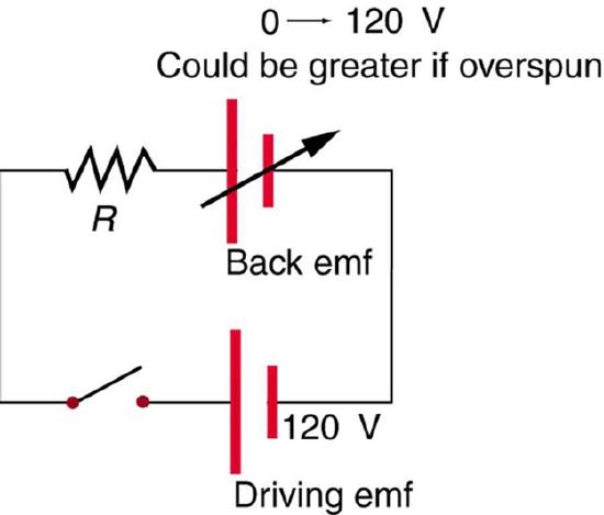
Back emf is the generator output of a motor, and so it is proportional to the motor’s angular velocity \(\omega\). It is zero when the motor is first turned on, meaning that the coil receives the full driving voltage and the motor draws maximum current when it is on but not turning. As the motor turns faster and faster, the back emf grows, always opposing the driving emf, and reduces the voltage across the coil and the amount of current it draws. This effect is noticeable in a number of situations. When a vacuum cleaner, refrigerator, or washing machine is first turned on, lights in the same circuit dim briefly due to the \(IR\) drop produced in feeder lines by the large current drawn by the motor. When a motor first comes on, it draws more current than when it runs at its normal operating speed. When a mechanical load is placed on the motor, like an electric wheelchair going up a hill, the motor slows, the back emf drops, more current flows, and more work can be done. If the motor runs at too low a speed, the larger current can overheat it (via resistive power in the coil, \(P = I^{2}R\)), perhaps even burning it out. On the other hand, if there is no mechanical load on the motor, it will increase its angular velocity \(\omega\) until the back emf is nearly equal to the driving emf. Then the motor uses only enough energy to overcome friction.
Consider, for example, the motor coils represented in Figure 1. The coils have a \(0.400 \Omega\) equivalent resistance and are driven by a 48.0 V emf. Shortly after being turned on, they draw a current \(I = V/R = \left(48.0 V\right)/\left(0.400 \Omega \right) = 120 A\) and, thus, dissipate \(P = I^{2}R = 5.67 kW\) of energy as heat transfer. Under normal operating conditions for this motor, suppose the back emf is 40.0 V. Then at operating speed, the total voltage across the coils is 8.0 V (48.0 V minus the 40.0 V back emf), and the current drawn is \(I = V/R = \left(8.0 V\right) / \left(0.400 \Omega \right) = 20 A\). Under normal load, then, the power dissipated is \(P = IV = \left(20A \right) / \left( 8.0V \right) = 160 W\). The latter will not cause a problem for this motor, whereas the former 5.76 kW would burn out the coils if sustained.
Summary
- Any rotating coil will have an induced emf—in motors, this is called back emf, since it opposes the emf input to the motor.
Glossary
- back emf
-
the emf generated by a running motor, because it consists of a coil turning in a magnetic field; it opposes the voltage powering the motor