

11.7: Motors and Meters
- Page ID
- 46224

\( \newcommand{\vecs}[1]{\overset { \scriptstyle \rightharpoonup} {\mathbf{#1}} } \)
\( \newcommand{\vecd}[1]{\overset{-\!-\!\rightharpoonup}{\vphantom{a}\smash {#1}}} \)
\( \newcommand{\dsum}{\displaystyle\sum\limits} \)
\( \newcommand{\dint}{\displaystyle\int\limits} \)
\( \newcommand{\dlim}{\displaystyle\lim\limits} \)
\( \newcommand{\id}{\mathrm{id}}\) \( \newcommand{\Span}{\mathrm{span}}\)
( \newcommand{\kernel}{\mathrm{null}\,}\) \( \newcommand{\range}{\mathrm{range}\,}\)
\( \newcommand{\RealPart}{\mathrm{Re}}\) \( \newcommand{\ImaginaryPart}{\mathrm{Im}}\)
\( \newcommand{\Argument}{\mathrm{Arg}}\) \( \newcommand{\norm}[1]{\| #1 \|}\)
\( \newcommand{\inner}[2]{\langle #1, #2 \rangle}\)
\( \newcommand{\Span}{\mathrm{span}}\)
\( \newcommand{\id}{\mathrm{id}}\)
\( \newcommand{\Span}{\mathrm{span}}\)
\( \newcommand{\kernel}{\mathrm{null}\,}\)
\( \newcommand{\range}{\mathrm{range}\,}\)
\( \newcommand{\RealPart}{\mathrm{Re}}\)
\( \newcommand{\ImaginaryPart}{\mathrm{Im}}\)
\( \newcommand{\Argument}{\mathrm{Arg}}\)
\( \newcommand{\norm}[1]{\| #1 \|}\)
\( \newcommand{\inner}[2]{\langle #1, #2 \rangle}\)
\( \newcommand{\Span}{\mathrm{span}}\) \( \newcommand{\AA}{\unicode[.8,0]{x212B}}\)
\( \newcommand{\vectorA}[1]{\vec{#1}} % arrow\)
\( \newcommand{\vectorAt}[1]{\vec{\text{#1}}} % arrow\)
\( \newcommand{\vectorB}[1]{\overset { \scriptstyle \rightharpoonup} {\mathbf{#1}} } \)
\( \newcommand{\vectorC}[1]{\textbf{#1}} \)
\( \newcommand{\vectorD}[1]{\overrightarrow{#1}} \)
\( \newcommand{\vectorDt}[1]{\overrightarrow{\text{#1}}} \)
\( \newcommand{\vectE}[1]{\overset{-\!-\!\rightharpoonup}{\vphantom{a}\smash{\mathbf {#1}}}} \)
\( \newcommand{\vecs}[1]{\overset { \scriptstyle \rightharpoonup} {\mathbf{#1}} } \)
\(\newcommand{\longvect}{\overrightarrow}\)
\( \newcommand{\vecd}[1]{\overset{-\!-\!\rightharpoonup}{\vphantom{a}\smash {#1}}} \)
\(\newcommand{\ket}[1]{\left| #1 \right>}\)
\(\newcommand{\bra}[1]{\left< #1 \right|}\)
\(\newcommand{\braket}[2]{\left< #1 \vphantom{#2} \right| \left. #2 \vphantom{#1} \right>}\)
\(\newcommand{\braopket}[3]{\left< #1 \vphantom{#2}\vphantom{#3} \right| #2 \vphantom{#1}\vphantom{#3} \left| #3 \vphantom{#1}\vphantom{#2} \right>}\)
\(\newcommand{\qmvec}[1]{\mathbf{\vec{#1}}}\)
\(\newcommand{\op}[1]{\hat{\mathbf{#1}}}\)
\(\newcommand{\expect}[1]{\langle #1 \rangle}\)
\(\newcommand{\dfn}[1]{\emph{\textbf{#1}}}\)
Learning Objectives
- Describe how motors and meters work in terms of force on a current loop.
Motors are the most common application of magnetic force on current-carrying wires. Motors have loops of wire in a magnetic field. When current is passed through the loops, the magnetic field exerts force on the loops, which rotates a shaft. Electrical energy is converted to mechanical work in the process. (See Figure \(\PageIndex{1}\).)
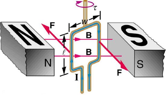
Figure \(\PageIndex{1}\): Force on a current loop. A current-carrying loop of wire attached to a vertically rotating shaft feels magnetic forces that produce a clockwise rotation as viewed from above.
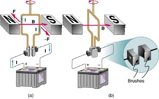
As the coil rotates, the force decreases to zero at \(\theta=0\). The force then reverses its direction once the coil rotates past \(\theta=0\). This means that, unless we do something, the coil will oscillate back and forth about equilibrium at \(\theta=0\). To get the coil to continue rotating in the same direction, we can reverse the current as it passes through \(\theta=0\) with automatic switches called brushes. (See Figure \(\PageIndex{2}\).)
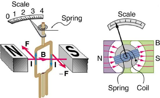
Meters, such as those in analog fuel gauges on a car, are another common application of magnetic force on a current-carrying loop. Figure \(\PageIndex{3}\) shows that a meter is very similar in construction to a motor. The meter in the figure has its magnets shaped to limit the effect of \(\theta\) by making \(B\) perpendicular to the loop over a large angular range. A linear spring exerts a counter-force that balances the current-produced force. This makes the needle deflection proportional to \(I\). If an exact proportionality cannot be achieved, the gauge reading can be calibrated. To produce a galvanometer for use in analog voltmeters and ammeters that have a low resistance and respond to small currents, we use a large loop area \(A\), high magnetic field \(B\), and low-resistance coils.
Glossary
- motor
- loop of wire in a magnetic field; when current is passed through the loops, the magnetic field exerts force on the loops, which rotates a shaft; electrical energy is converted to mechanical work in the process
- meter
- common application of magnetic force on a current-carrying loop that is very similar in construction to a motor; by design, the force is proportional to \(I\) and not \(\theta\), so the needle deflection is proportional to the current