
10.7: Example- Crown Glass
- Page ID
- 23237
The dependence of the reflectivity on angle of incidence for a typical nondissipative material, Crown glass, is shown in Figure (10.7.13) and in Figure (10.7.14) for a wavelength of 0.5145 microns, see Table(10.3.1). Fig.(10.7.13) shows the variation of the ratio ER/E0 (Equation (10.5.27)) as a function of the angle of incidence for S-polarized light.
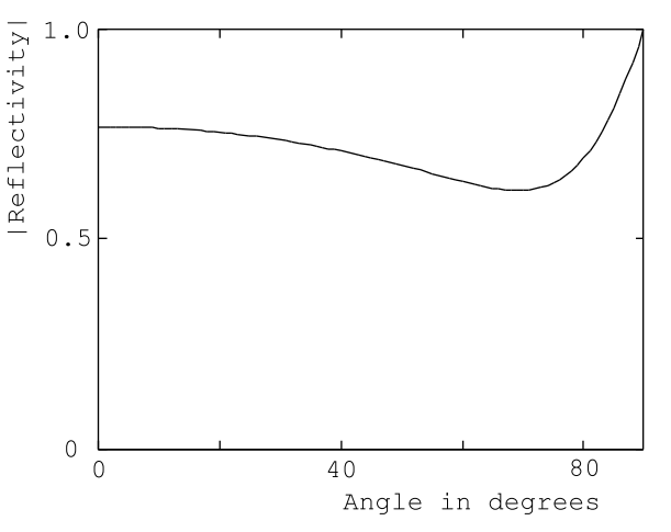
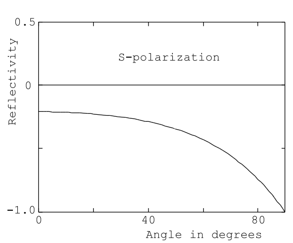
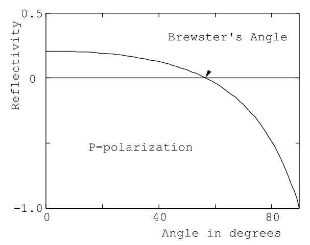
Fig.(10.7.14) shows the variation of the ratio HR/H0 (Equation (10.5.28)) as a function of the angle of incidence for P-polarized light. Notice that the angular dependence of the reflectivity for S-polarized light is qualitatively similar to that of copper. Of course, the reflectivity of Crown glass has only a real part because there are negligible losses in the glass and therefore the reflected electric field is 180◦ out of phase with the incident electric field. The angular variation of the reflection coefficient for P-polarized light is more interesting because the reflectivity goes to zero at approximately 57◦ , Figure (10.7.14). This angle is called Brewster’s angle. Unpolarized light incident on a lossless dielectric material at Brewster’s angle yields reflected light that is entirely S-polarized, ie. the electric vector in the reflected beam is oriented perpendicular to the plane of incidence. Before the advent of polaroid filters a stack of glass plates with the light incident at Brewster’s angle was used to produce plane polarized light. Brewster’s angle windows are used on each end of the plasma tubes in gas lasers.The light emitted from such a laser is plane polarized because the gain of the system is greater for P-polarized light than it is for S-polarized radiation due to the greater reflection losses at the plasma tube windows for S-polarized light.
It can be shown that at Brewster’s angle the reflected light and the light transmitted into the dielectric medium form an angle of exactly 90◦ . This is a handy device for remembering how to determine Brewster’s angle. The demonstration that the angle between the reflected beam and the transmitted beam is 90◦ for light incident on a dielectric medium from vacuum depends upon the two relations
\[\text{n} \cos \theta=\cos \phi, \nonumber \]
(from Equation (10.5.28)) and
\[\sin \theta=n \sin \phi \nonumber \]
from Snell’s law. Using the fact that the sum of the squares of the sin and cos functions is identically equal to 1 the above relations can be manipulated to give
\[\sin \theta=\frac{n}{\sqrt{n^{2}+1}}=\cos \phi, \nonumber \]
and
\[\cos \theta=\frac{1}{\sqrt{\text{n}^{2}+1}}=\sin \phi. \nonumber\]
It follows from these relations that θ and \(\phi\) are complementary angles, and that tan θ= n.