
13.5: Chapter 5
- Page ID
- 25304

Problem (5.1)
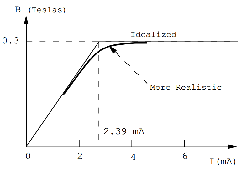
A very long solenoid is wound with N= 105 turns per meter. It is filled with a very permeable material, but one that becomes saturated at a critical value of B: i.e. for B< 0.30 teslas the relative permeability is µr= 103, but for B> 0.30 Teslas the relative permeability becomes very nearly equal to µr= 1.0.
(a) Make a sketch showing approximately how one would expect the B-field inside the material in the solenoid to vary with the dc current through the solenoid windings.
(b) Suppose that a secondary coil of radius R=2 cm and 1000 turns was wound on the above solenoid. Calculate the emf induced in the secondary coil if the current through the primary varies as
\[I(t)=I_{0} \operatorname{Sin} \omega t\nonumber,\]
where I0= 1 mAmp (10-3 Amps), and ω= 2\(\pi\)F corresponds to 60 Hz.
(c) Calculate the emf induced in the secondary coil if a dc current of 10 mAmps flows through the solenoid windings in addition to the above ac current.
The controll of an output ac signal amplitude by means of a relatively small dc control current formed the basis for a device called a magnetic amplifier. In effect, the efficiency of a transformer could be altered by a dc current and therefore large amounts of ac power could be controlled by means of relatively small amounts of dc power. Magnetic amplifiers enjoyed a brief spell of popularity in the late 1950's and the early 1960's. They were superceded by the developement of transistors which could handle large amounts of power.
Answer (5.1).
(a) Inside the solenoid H= NI = 105I Amps/meter. When the B field is less than 0.30 Teslas the relative permeability is given by µr= 103, so that
\[\text{B}=\mu \text{H}=\mu_{\text{r}} \mu_{0} \text{NI}=125.7 \text { I Teslas. }\nonumber\]
The current required to saturate the core is
\[I=\frac{0.30}{125.7}=\mathbf{2.39 \times 10^{-3} \text {Amps }=2.39 \text { mAmps }}\nonumber.\]
Upon saturation, the B-field increases only very slowly with the current because M remains fixed at the saturation value:
\[\text{B}=\mu_{0} \text{M}+\mu_{0} \text{H} \cong 0.3 \text { Teslas }\nonumber\]
since µ0H is relatively small. At I= 0.1 Amps (~40x the current required to saturate the core) µ0H= 0.013 Teslas, an increase of only 3% in B.
(b) For a small current µr= 1000 and so for an amplitude of 1 mA the field varies as
\[B = 0.126 \sin\omega t \text{ Teslas.}\nonumber\]
The flux through the secondary coil is given by
\[\phi=\left(10^{3}\right)\left(\pi \mathrm{R}^{2}\right)(\mathrm{B})=0.158 \sin \omega t \text{ Webers. }\nonumber\]
\[e=-\frac{d \phi}{d t}= 59.6 \cos\omega t \text{ Volts, }\nonumber\]
since ω= 2\(\pi\)(60) = 377 radians/sec.
(c) The dc current of 10 mAmps would bias the core of the solenoid into the region where the relative permeability is only µr= 1.0. The voltage induced in the secondary coil would decrease by a factor of 1000: the output signal would fall to ~60 mV from its initial value of ~60 Volts.
Problem (5.2)
A long straight thin wire carries a current of 5 Amps; it runs parallel with the interface between vacuum and a superconducting plane for which the relative permeability is µr= 0. Calculate the force on the wire due to its image if the wire is a distance z=1 cm from the plane. In a superconductor the field B is zero.
Answer (5.2)
The image current I' has the same magnitude as the driving current I, but is opposite in sign, and is located z from the interface, but in the superconductor;
I' = - I.
The current plus its image generate the magnetic field in the region outside the superconductor. The normal component of B is zero at the superconducting surface as is required by div B=0 plus the condition B=0 in the superconductor. The component of B or of H parallel with the interface does not matter since surface currents flow in the superconductor to shield its interior so that H=0.
The field generated by I' at the wire carrying the current I is given by
\[|\mathbf{H}|=\frac{\left|I^{\prime}\right|}{2 \pi(2 z)}=\frac{I}{4 \pi z}\nonumber.\]
The force on the wire per unit length is given by
\[F=\frac{\mu_{0} I^{2}}{4 \pi z}=\frac{(25)\left(4 \pi \times 10^{-7}\right)}{(4 \pi)\left(10^{-2}\right)}=25 \times 10^{-5} \text {Newtons / m }\nonumber.\]
The direction of the force is such as to repell the wire from the interface. The above force is sufficient to lift a weight of approximately 25 miligrams per meter. This is pretty feeble; however, the force increases with the square of the current so that for 500 Amps the force would support ~0.25 kg/meter.
Problem (5.3)
A permanent magnetic dipole, m, is brought up to the plane interface between vacuum, µr=1, and a superconductor, µr=0. The dipole is located a distance z in front of the interface.
(a) Show that the image magnetic charge induced in the superconductor by the magnetic charge qm a distance z in front of the interface is equal to qm and is located a distance z behind the interface. The image charge is required in order to satisfy the condition divB=0 and also the condition B=0 in the superconductor.
(b) Use the results of part (a) in order to calculate the force exerted on a magnetic dipole by its image when the dipole is oriented parallel with the interface.
(c) Calculate the force on the dipole when it is oriented normal to the interface.
(d) Given 1 cc of permanently magnetized material, estimate the heighth at which it would float above a superconducting plane. Let the density of the material be 4.5 gm/cc, and let its magnetization density be M= 1.59x10⁵ Amps/meter ( these parameters are appropriate for Barium ferrite BaO.6Fe2O3 - this is a common ferromagnetic insulator called Ferroxdure).
Answer (5.3)
The field in the vacuum which is generated by a point magnetic charge and its image must be such that the normal component of B vanishes on the superconducting surface (see the figure).
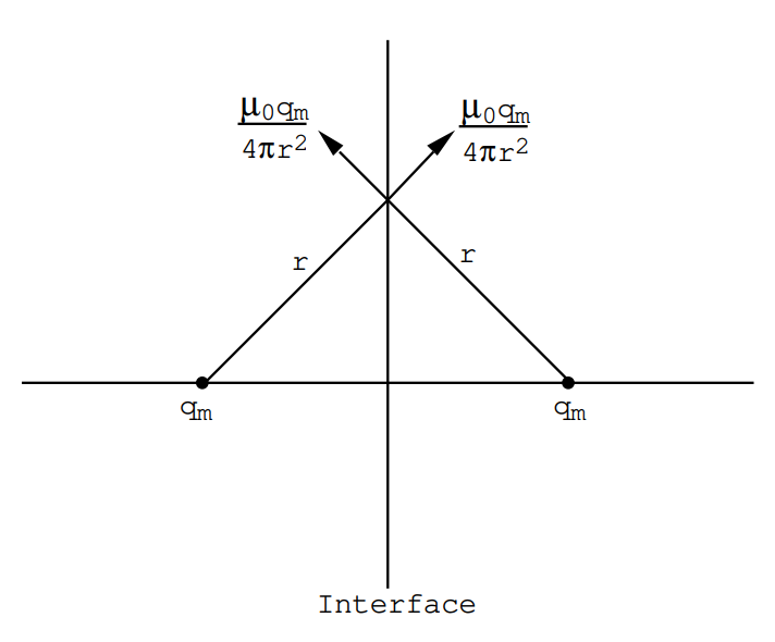
In this way the conditions divB=0 and B=0 can both be satisfied. The tangential component of B need not be zero; surface currents flow in a very thin surface layer (~ 10-8 meters thick) which shield the interior of the superconductor.
(b) Dipole moment parallel with the Interface.
The component of force normal to the surface is the same for each charge on the dipole, therefore there is no torque acting on the dipole. The two forces acting on a given charge are:
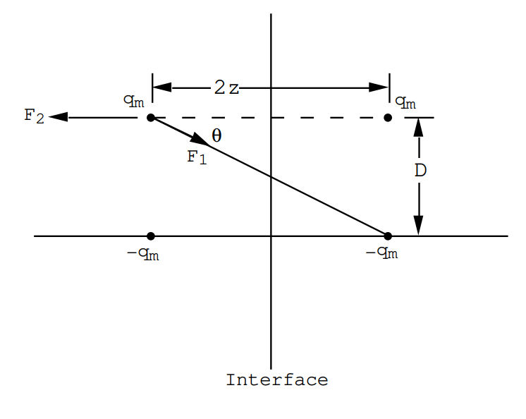
an attractive force
\[\text{F}_{1}=\frac{\mu_{0} \text{q}_{\text{m}}^{2}}{4 \pi} \frac{\cos \theta}{\left(4 \text{z}^{2}+\text{D}^{2}\right)}\nonumber,\]
and a repulsive force
\[\text{F}_{2}=\frac{\mu_{0} \text{q}_{\text{m}}^{2}}{4 \pi} \frac{1}{4 \text{z}^{2}}\nonumber.\]
The net repulsive force on the dipole is given by
\[\text{F}=\frac{2 \mu_{0} \text{q}_{\text{m}}^{2}}{4 \pi}\left(\frac{1}{4 \text{z}^{2}}-\frac{2 \text{z}}{\left(4 \text{z}^{2}+\text{D}^{2}\right)^{3 / 2}}\right)\nonumber,\]
or
\[\text{F}=\frac{2 \mu_{0} \text{q}_{\text{m}}^{2}}{4 \pi}\left(\frac{3 \text{D}^{2}}{32 \text{z}^{4}}\right)\nonumber.\]
But m= qmD so that the repulsive force can be written
\[\mathbf{F=\frac{\mu_{0}}{\mathbf{4} \pi} \frac{3 \mathbf{m}^{2}}{16 \mathbf{z}^{4}}}\nonumber.\]
(c) Dipole moment normal to the Interface.
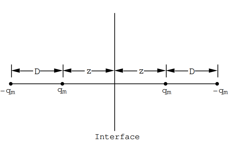
The net repulsive force on the dipole is given by
\[F=\frac{\mu_{0} q_{m}^{2}}{4 \pi}\left(\frac{1}{4 z^{2}}+\frac{1}{4 z^{2}(1+D / z)^{2}}-\frac{2}{4 z^{2}(1+D / 2 z)^{2}}\right)\nonumber.\]
Now \(\left(1+\frac{D}{z}\right)^{-2}=1-\frac{2 D}{z}+3\left(\frac{D}{z}\right)^{2}+\ldots\)
and \(\left(1+\frac{D}{2 z}\right)^{-2}=1-\frac{D}{z}+\frac{3}{4}\left(\frac{D}{z}\right)^{2}+\ldots\)
so that
\[F=\frac{\mu_{0}}{4 \pi} \frac{q_{m}^{2}}{4 z^{2}}\left(\frac{3}{2} \frac{D^{2}}{z^{2}}\right)=\mathbf{\frac{\mu_{0}}{4 \pi} \frac{3 m^{2}}{8 z^{4}}}\nonumber\]
This repulsive force is twice as large as the repulsive force when the dipole is oriented so that it is parallel with the interface.
(d) The weight of 1 cc of Ferroxdure is 4.5 gm or 4.5x10⁻³ kg. The gravitational force is Fg= 4.41x10⁻² Newtons. The total magnetic moment for this piece of material is
\[\text{m}=\text{MV}=\left(1.59 \times 10^{5}\right)\left(10^{-6}\right)=0.159 \text{Amp} \cdot \text{m}^{2}\nonumber.\]
The repulsive force when the moment is parallel with the plane (the stable configuration) will be
\[F=\left(10^{-7}\right)\left(\frac{3}{16}\right) \frac{\left(2.53 \times 10^{-2}\right)}{z^{4}}=4.41 \times 10^{-2} \text{N}\nonumber.\]
or
\[\mathbf{z = 1.02 \times 10^{-2} \text{meters.}}\nonumber\]
The magnet would float approximately 1 cm above the superconducting plane.
Problem (5.4)
A short solenoid is constructed of 100 turns wound evenly on a cylindrical form. The length of the windings is L= 10 cm, and the mean radius of the coil is R= 5 cm. Find an expansion in Legendre polynomials for the magnetic potential in the interior of the solenoid, and estimate the radius of the region around the solenoid center within which the field is uniform to better than 1%. In the expansion of the field along the solenoid axis you may discard terms of order z4 and higher powers.
Answer (5.4)
The field along the axis of a short solenoid is given by
\[\text{B}_{\text{z}}=\frac{\mu_{0} \text{NI}}{2}\left(\frac{(\text{L} / 2+\text{z})}{\sqrt{\text{R}^{2}+\left(\frac{\text{L}}{2}+\text{z}\right)^{2}}}+\frac{(\text{L} / 2-\text{z})}{\sqrt{\text{R}^{2}+\left(\frac{\text{L}}{2}-\text{z}\right)^{2}}})\right., \quad \text{eqn (3.2.10).}\nonumber\]
Note that the term in the brackets is a dimensionless number so that one can use z,R,L measured in cm rather than meters. For our case N= 1000 turns/meter, so that for a current of 1 Amp
\(\text{B}_{0}=\frac{\mu_{0} \text{NI}}{2}=6.283 \times 10^{-4} \text {Teslas }\),
and
\[\text{B}_{\text{z}}(\text{z})=\text{B}_{0}\left(\frac{(5+\text{z})}{\sqrt{(\text{z}+5)^{2}+25}}+\frac{(5-\text{z})}{\sqrt{(\text{z}-5)^{2}+25}}\right)\nonumber,\]
where z is measured in cm. The idea is to expand this function in powers of z.
At z=0 \(B_{z}(0)=B_{0} \sqrt{2}\)
\(\left.\frac{d B_{z}}{d z}\right|_{0}=0\)
\(\left.\frac{\text{d}^{2} \text{B}_{z}}{\text{d} \text{z}^{2}}\right|_{0}=-\frac{3 \text{B}_{0} \sqrt{2}}{100}=-0.04243 \text{B}_{0}\)
\(\left.\frac{d^{3} B_{z}}{d z^{3}}\right|_{0}=0\)
\(\left.\frac{\text{d}^{4} \text{B}_{z}}{\text{d} \text{z}^{4}}\right|_{0}=-\frac{3 \text{B}_{0}}{1000 \sqrt{2}}=-0.0021213 \text{B}_{0}\)
etc.
But
\[\text{B}_{z}(\text{z})=\text{B}_{0} \sqrt{2}+\left.\frac{1}{2} \frac{\text{d}^{2} \text{B}_{2}}{\text{d} \text{z}^{2}}\right|_{0} \text{z}^{2}+\left.\frac{1}{24} \frac{\text{d}^{4} \text{B}_{2}}{\text{d} \text{z}^{4}}\right|_{0} \text{z}^{4}+\cdots\nonumber\]
Thus
\[\text{B}_{z}(\text{z})=\text{B}_{0} \sqrt{2}\left(1-\frac{3 \text{z}^{2}}{200}+\frac{\text{z}^{4}}{16000} \cdot+\ldots \text{O}\left(\text{z}^{6}\right)\right)\nonumber\]
This field can be obtained from a potential function
\[B_{z}=-\frac{\partial V}{\partial z}\nonumber,\]
where
\[V(z)=-B_{0} \sqrt{2}\left(z-\frac{z^{3}}{200}+O\left(z^{5}\right)\right). \quad \quad \quad \quad (1) \nonumber\]
V(z) must satisfy ∇2V=0, therefore
\[\text{V}(\text{z})=\sum_{\text{n}=1}^{\infty} \text{a}_{\text{n}} \text{r}^{\text{n}} \text{P}_{\text{n}}(\cos \theta)\nonumber;\]
the terms in \(\frac{1}{r^{n+1}}\) must be omitted because they blow up at r=0.
\[V(r, \theta)=a_{1} r \cos \theta+\frac{a_{2} r^{2}}{4} \quad(1+3 \cos 2 \theta)+\frac{a_{3} r^{3}}{8}(3 \cos \theta+5 \cos 3 \theta)+\frac{a_{4} r^{4}}{64} (9+20 \cos 2 \theta+35 \cos 4 \theta)+\nonumber\]
At θ=0 the radius r becomes equal to the cylindrical co-ordinate z, and since Cosθ=1 this series becomes
\[V(z)=a_{1} z+a_{2} z^{2}+a_{3} z^{3}+a_{4} z^{4}+\dots \quad \quad \quad \quad (2) \nonumber\]
from which by comparison with eqn.(1) one finds
\[\begin{array}{l} \text{a}_{1}=-\text{B}_{0} \sqrt{2} \\ \text{a}_{2}=0 \\ \text{a}_{3}=\frac{\text{B}_{0} \sqrt{2}}{200} \\ \text{a}_{4}=0, \end{array}\nonumber\]
and so on. Thus to terms of order z5 one has
\[\mathbf{V}(\mathbf{r}, \theta)=-\mathbf{B}_{0} \sqrt{\mathbf{2}}\left(\operatorname{rcos} \theta-\frac{\mathbf{r}^{3}}{1600}(3 \cos \theta+5 \cos 3 \theta)\right.\nonumber.\]
\[\text{B}_{\text{r}}=-\frac{\partial \text{V}}{\partial \text{r}}=\text{B}_{0} \sqrt{2}\left(\cos \theta-\frac{3 \text{r}^{2}}{1600}(3 \cos \theta+5 \cos 3 \theta)\right)\nonumber,\]
\[\text{B}_{\theta}=-\frac{1 \partial \text{V}}{\text{r} \partial \theta}=\text{B}_{0} \sqrt{2}\left(-\sin \theta+\frac{3 \text{r}^{2}}{1600} \quad(\sin \theta+5 \sin 3 \theta)\right)\nonumber.\]
The first two terms, i.e. \(\text{B}_{\text{r}}=\text{B}_{0} \sqrt{2} \cos \theta\) and \(\text{B}_{\theta}=-\text{B}_{0} \sqrt{2} \sin \theta\), correspond to a uniform field \(B_{z}=B_{0} \sqrt{2}\) Teslas. The correction to the axial field component, Bz, is given by
\[\mathbf{\frac{\Delta \mathbf{B}_{\mathbf{z}}}{\mathbf{B}_{0} \sqrt{\mathbf{2}}}=-\frac{3 \mathbf{r}^{2}}{1600} \left(1+2 \cos ^{2} \theta+5 \cos \theta \cos 3 \theta+5 \sin \theta \sin 3 \theta\right)}\nonumber\]
since \(\text{B}_{\text{z}}=\text{B}_{\text{r}} \text{Cos} \theta-\text{B}_{\theta} \operatorname{Sin} \theta\). The term in the brackets varies between -4 and +8.
The correction to the transverse magnetic field component, Bρ, where \(\text{B}_{\text{p}}=\text{B}_{\text{r}} \operatorname{Sin} \theta+\text{B}_{\theta} \cos \theta\) is given by
\[\mathbf{\frac{B_{\rho}}{B_{0} \sqrt{2}}=-\frac{3 r^{2}}{1600} (2 \sin \theta \cos \theta+5 \sin \theta \cos 3 \theta-5 \cos \theta \sin 3 \theta)}\nonumber.\]
The term in the brackets varies from -4 to +4. It is clear from these expressions that the deviations ∆Bz,Bρ will be less than \(B_{0} \sqrt{2}\left(\frac{3 r^{2}}{200}\right)\) for all angles. The field will be uniform to better than 1% within a sphere of radius r= 0.816 cm, and uniform to better than 10% within a sphere of radius r= 2.582 cm around the center of the solenoid.
Problem (5.5).
A magnetic shield is made of a permeable material in the form of a long cylinder having an inner radius R1 and an outer radius R2. The relative permeability of the cylinder material is µr. If this shield is placed in a uniform magnetic field, B0, that is directed transverse to the cylinder axis what will be the field inside the cylinder? You may treat the cylinder as if it were infinitely long. Inside and outside the cylinder the relative permeability is µr=1.
Answer (5.5)
There are clearly three regions involved in this problem:
(1) the region inside the cylinder, µr=1;
(2) the region inside the cylinder walls, µr;
(3) the region outside the cylinder, µr=1.
In each of these three regions ∇2V=0, where H= - gradV. Therefore, in each region the potential can be expanded in a series of the form
\[V(r, \theta)=\sum_{n=1}^{\infty}\left(a_{n} r^{n}+\frac{b_{n}}{r^{n}}\right) \cos n \theta.\nonumber\]
It proves not to be necessary to use terms for n>1. Inside the cylinder: V1 = arCosθ
In the cylinder walls: \( V_{2}=a_{0} r \cos \theta+\frac{b_{0} \cos \theta}{r}\),
one must use both terms because neither term becomes singular in the cylinder walls;
Outside the cylinder: \(V_{3}=-H_{0} r \cos \theta+\frac{b C o s \theta}{r}).
Boundary Conditions.
At r=R1 (the inner wall)
\[V_{1}=V_{2}\nonumber\]
\[\frac{d V_{1}}{d r}=\mu_{r} \frac{\partial V_{2}}{\partial r}\nonumber\]
or
\[a=a_{0}+\frac{b_{0}}{R_{1}^{2}}\quad\quad \quad \quad (1) \nonumber\]
\[\text{a}=\mu_{\text{r}} \text{a}_{0}-\frac{\mu_{\text{r}} \text{b}_{0}}{\text{R}_{1}^{2}}\quad\quad \quad \quad (2) \nonumber\]
At r=R2 (the outer wall)
\[\mathrm{V}_{2}=\mathrm{V}_{3}\nonumber\]
\[\mu_{r} \frac{\partial V_{2}}{d r}=\frac{\partial V_{3}}{d r}\nonumber\]
or
\[a_{0}+\frac{b_{0}}{R_{2}^{2}}=-H_{0}+\frac{b}{R_{2}^{2}}\quad\quad \quad \quad (3)\nonumber\]
\[\mu_{r} a_{0}-\frac{\mu_{r} b_{0}}{R_{2}^{2}}=-H_{0}-\frac{b}{R_{2}^{2}} \quad\quad \quad \quad (4) \nonumber\]
These 4 equations can be solved for the 4 unknowns a,a0,b0, and b. The result is
\[a=\frac{-4 \mu_{r} H_{0}}{\left(\left(\mu_{r}+1\right)^{2}-\left(\mu_{r}-1\right)^{2}\left(\frac{R_{1}}{R_{2}}\right)^{2}\right)}\nonumber.\]
The ratio of the field inside the cylinder to the field outside the cylinder is given by
\[\frac{B_{i n}}{B_{o u t}}=\frac{4 \mu_{r}}{\left.\left(\mu_{r}+1\right)^{2}-\left(\mu_{r}-1\right)^{2}\left(\frac{R_{1}}{R_{2}}\right)^{2}\right)}\nonumber,\]
or
\[\mathbf{\frac{B_{i n}}{B_{o u t}} \cong \frac{4}{\mu_{r}\left(1-\left(\frac{R_{1}}{R_{2}}\right)^{2}\right)}}\nonumber.\]
The relative permeability for Supermalloy is µr~ 105 for B< 0.7 Teslas. In a typical application for shielding a photomultiplier tube one would have R1= 2.5 cm and R2= 2.6 cm or \(\frac{R_{1}}{R_{2}}=0.962 \). For such a case
\[\mathbf{\frac{B_{i n}}{B_{0 u t}}=\frac{4 \times 10^{-5}}{0.0754}=5.3 \times 10^{-4}}\nonumber.\]
Problem (5.6)
A magnetic shield is constructed of a permeable material in the form of a long cylinder of length L and having an inner radius R1 and an outer radius R2. The relative permeability of the shield material is µr. Let this shield be placed in a field B0 parallel with the cylinder axis. Estimate the field at the center of the shield if L is much greater than the radii R1 and R2.
This problem cannot be easily solved in closed form; however, one can argue as follows:
(1) Most of the field inside the cylinder will be sucked into the permeable material of the cylinder walls. One can estimate the strength of B inside the cylinder wall from conservation of flux.
(2) Assuming that B is constant within the cylinder walls then the magnetization M will also be uniform. The discontinuities in M at the cylinder ends will act as field sources. These sources can be used to estimate the field at the center of the cylinder. As a crude first approximation one can assume that all of the magnetic charges on the cylinder ends are the same distance from its center because L>>R.
Answer (5.6)
The region inside the cylinder originally contained the flux \(\phi=\text{B}_{0} \pi \text{R}_{1}^{2}\). This flux becomes concentrated in the cylinder wall. The resulting B-field in the wall must be such that
\[ \text{B}_{\text{W}} \pi\left(\text{R}_{2}^{2}-\text{R}_{1}^{2}\right)=\text{B}_{0} \pi \text{R}_{1}^{2}\nonumber.\]
Therefore \(\text{B}_{\text{W}}=\frac{\text{B}_{0}}{(\left(\frac{\text{R}_{2}}{\text{R}_{1}}\right)^{2}-1)} \).
But \(\text{B}_{\text{W}}=\mu_{0}(\text{H}+\text{M}) \cong \mu_{0} \text{M}\)
since for a very permeable material \(\text{H}=\frac{\text{B}}{\mu_{0} \mu_{\text{r}}} \sim 0\).
Consequently, \(\text{M}=\frac{\text{B}_{\text{W}}}{\mu_{0}}=\frac{\text{B}_{0} / \mu_{0}}{\left(\left(\frac{\text{R}_{2}}{\text{R}_{1}}\right)^{2}-1\right)}\), Amps/m.
The discontinuities in M give two rings of magnetic charge, each of average radius R= (R1+R2)/2, and of total strength
\[ Q=M \pi\left(R_{2}^{2}-R_{1}^{2}\right)=M \pi R_{1}^{2}\left(\left(\frac{R_{2}}{R_{1}}\right)^{2}-1\right)\nonumber.\]
If the length of the cylinder is much longer than its radii, then crudely speaking, the field at the center of the cylinder must be given approximately by two point charges, +Q and -Q, located a distance L/2 from the center of the cylinder: thus
\[ \text{H} \sim \frac{2 \text{Q}}{4 \pi(\text{L} / 2)^{2}}=\frac{2 \text{B}_{0} \text{R}_{1}^{2}}{\mu_{0} \text{L}^{2}} \nonumber,\]
or
\[\frac{B}{B_{0}} \cong 2\left(\frac{R_{1}}{L}\right)^{2}\nonumber.\]
Notice that this expression is independent of µr, but µr must be large enough so that H inside the shield material can be neglected when compared with M. In order to obtain effective shielding the field Bw in the cylinder walls must be less than the saturation field. For an iron based shielding material the field B at saturation is typically ~ 1 Tesla. If the driving field B0 is the earth's magnetic field, ~10-4 Tesla, the ratio of the inner radius R1 to the shield thickness d must be less than 5000. This condition is easily met since for typical values R1= 2.5 cm and R2= 2.6 cm the ratio \(\frac{R_{1}}{d}=25\).
Problem (5.7)
A solenoid is constructed of N=100 turns of wire. The mean diameter of the windings is D=5 cm and the length of the windings is L= 10 cm. This coil is to be used to generate a field of 10 Tesla in vacuum. In the following calculations the coil may be approximated as an infinitely long solenoid.
(a) What current would be required to generate a field of 10 Teslas?
(b) Estimate the magnetic force acting to change the length of the solenoid windings. Do these forces tend to lengthen or to shorten the windings?
(c) Estimate the tension in the wire of which the coil is wound.
Answer (5.7)
(a) For a long solenoid in vacuum \(\text{B}=\frac{\mu_{0} \text{NI}}{\text{L}}\), where N= 100 is the total number of turns, and L is the length. For the present example, L= 0.10 m and
\[\text{B}=\frac{\left(4 \pi \times 10^{-7}\right)\left(10^{2}\right) I}{0.1}=4 \pi \times 10^{-4} \quad \text{I} \quad \text { Teslas}.\nonumber\]
In order to generate 10 Teslas the current required is
\[\mathbf{I=7.96 \times 10^{3} \text { Amps.}}\nonumber\]
(b) The energy stored in the solenoid is approximately given by
\[\text{U}_{\text{B}}=\text{V} \frac{\text{B}^{2}}{2 \mu_{0}}=\left(\frac{\pi \text{D}^{2}}{8}\right) \frac{\mu_{0} \text{N}^{2} \text{I}^{2}}{\text{L}}, \text { Joules }\nonumber.\]
Therefore \(\frac{\partial \text{U}_{\text{B}}}{\partial \text{L}}=-\left(\frac{\pi \text{D}^{2}}{8}\right) \frac{\mu_{0} \text{N}^{2} \text{I}^{2}}{\text{L}^{2}}=-\frac{\pi \text{D}^{2}}{8 \mu_{0}} \text{B}^{2}\).
The solenoid will tend to contract along its length. The force on the windings is given by
\[F=\left|\frac{\partial U_{B}}{\partial L}\right|=\frac{(\pi)(25)\left(10^{-4}\right)\left(10^{2}\right)}{\left(32 \pi \times 10^{-7}\right)}=7.8 \times 10^{4} \text { Newtons }\nonumber.\]
This force would suspend a weight of 8000 kg! The turns of the solenoid must be very securely held in place.
(c) The field B is independent of the solenoid diameter. One can write
\[\text{U}_{\text{B}}=\frac{\pi \text{D}^{2} \text{L}}{8 \mu_{0}} \text{B}^{2}\nonumber,\]
so that
\[ \frac{\partial \text{U}_{\text{B}}}{\partial \text{D}}=\frac{\pi \text{DL}}{4 \mu_{0}} \text{B}^{2}\nonumber.\]
If the mean diameter increases by dD the length of the solenoid wire increases by dS= N\(\pi\) dD, therefore
\[\frac{\partial \text{U}_{\text{B}}}{\partial \text{S}}=\frac{1}{\text{N} \pi} \frac{\partial \text{U}_{\text{B}}}{\partial \text{D}}=\frac{\text{D} \text{L} \text{B}^{2}}{4 \text{N} \mu_{0}}\nonumber.\]
The tension on the wire will be given by
\[F=\frac{\left(50 \times 10^{-4}\right)\left(10^{2}\right)}{(4)(4 \pi)\left(10^{2}\right)\left(10^{-7}\right)}=0.995 \times 10^{3} \text { Newtons }\nonumber.\]
This force is approximately the equivalent of a 100 kg weight.
Problem (5.8)
A rigid loop of wire has the form of a triangle, The base of the triangle is 5 cm long and the height of the triangle is 5 cm. This object is placed in a uniform magnetic field of B= 1 Tesla such that its area embraces no flux. What will be the torque on the triangle if it carries a current of 1 Amp?
Answer (5.8).
The magnetic energy of the system contains three terms:
\[\text{U}_{\text{B}}=\frac{1}{2} \text{L}_{11} \text{I}_{1}^{2}+\frac{1}{2} \text{L}_{22} \text{I}_{2}^{2}+\text{L}_{12} \text{I}_{1} \text{I}_{2}\nonumber.\]
The first two terms are the self-energy of the sources of the uniform field and the self-energy of the triangle: these terms do not change when the triangle is rotated. The last term is dependent on the angle between the plane of the triangle and the applied magnetic field. The flux through the triangle is given by
\[\phi_{2}=\operatorname{BASin} \theta=(\text{KASin} \theta) \quad I_{1}\nonumber\]
where I1 is the current associated with the source field B. This expression gives the mutual inductance coefficient L12:
\[\text{L}_{12}=\text{KASin} \theta\nonumber,\]
and
\[\frac{\partial \text{U}_{\text{B}}}{\partial \theta}=\text{I}_{1} \text{I}_{2} \quad \text{KACos} \theta=\left(\text{I}_{2} \text{BA}\right) \operatorname{Cos} \theta\nonumber.\]
The torque on the triangle is just
\[\mathbf{\tau=\frac{\partial U_{B}}{\partial \theta}=I_{2} BA\cos \theta=25 \times 10^{-4} \text { Newton meters at } \theta=0.}\nonumber\]
Problem (5.9)
A charged particle moves in a uniform magnetic field B which changes slowly with time. ( Slowly here means that the rate of change is slow compared with the cyclotron frequency).
(a) Show that the radius R of the particle orbit must change in such a way that
\[\text{BdR}=-\frac{\text{RdB}}{2}.\nonumber\]
This change in radius is the consequence of the changing magnetic field that creates an electric field that exerts a force on the particle.
(b) Show that the change in radius of part (a) corresponds to a change in the orbit area in such a way as to keep the flux through the orbit constant.
(c) Show that the orbital magnetic moment associated with the particle motion remains constant as the field changes.
Answer (5.9)
(a) The force on a charged particle in a magnetic field is given by qvB where v is the transverse component of velocity. One can ignore any motion along the magnetic field for this problem. From mechanics, and for a particle of mass m,
\[\frac{m v^{2}}{R}=q v B\nonumber,\]
so that \(\text{v}=\frac{\text{q}}{\text{m}} \text{BR}\). (1)
If B changes with time there is induced an electric field since \(\operatorname{curl} \mathbf{E}=-\frac{d \mathbf{B}}{\partial t}\). In cylindrical polar co-ordinates there will be only a component Eθ because the field is uniform and has only a z-component:
\[\frac{1}{r} \frac{d}{d r}(r E \theta)=-\frac{\partial B_{z}}{\partial t}\nonumber.\]
But since Bz is independent of position \(\text{E}_{\theta}=-\frac{\text{R}}{2}\left(\frac{\partial \text{B}_{\text{z}}}{\partial \text{t}}\right)\) along the particle orbit. A moments thought will reveal that the direction of Eθ is such as to cause the particle velocity to increase, therefore
\[m \frac{d v}{d t}=q\left|E_{\theta}\right|=\frac{q R}{2} \frac{d B}{d t}\nonumber,\]
or
\[\text{d} \text{v}=\left(\frac{\text{q} \text{R}}{2 \text{m}}\right) \text{dB}\nonumber . \quad \quad \quad \quad (2)\]
However, from (1) \(\text{d} \text{v}=\left(\frac{\text{q}}{\text{m}}\right) \quad(\text{BdR}+\text{RdB})\)
so that from (2) \(\frac{\text{q} \text{R}}{2 \text{m}} \text{dB}=\frac{\text{qB}}{\text{m}} \text{dR}+\frac{\text{qR}}{\text{m}} \text{dB}\)
and so \(\frac{q B}{m} d R=-\frac{q R}{2 m} d B\)
or \(\text{BdR}=-\frac{\text{RdB}}{2}\) (3)
(b) The flux through the particle orbit is
\[\phi=\pi \text{R}^{2} \text{B}\nonumber.\]
\[\text{d} \phi=\pi \quad\left(2 \text{RBdR}+\text{R}^{2} \text{dB}\right)\nonumber.\]
But from (3) above
\[\text{d} \phi=\pi\left(-\text{R}^{2} \text{dB}+\text{R}^{2} \text{dB}\right)=0\nonumber.\]
In other words, the flux through the orbit is conserved.
(c) The magnetic moment associated with the orbit is given by
\[\text{m}_{\text{z}}=\left(\pi \text{R}^{2}\right) \text{I}\nonumber,\]
where the current I is given by \(I=\frac{q V}{2 \pi R}\). Thus
\[\text{m}_{\text{z}}=\left(\pi \text{R}^{2}\right)\left(\frac{\text{qv}}{2 \pi \text{R}}\right)=\frac{\text{qvR}}{2}\nonumber.\]
Using eqn.(1) this can be written \(m_{z}=\left(\frac{q R}{2}\right)\left(\frac{q}{m}\right)(B R)=\frac{q^{2}}{2 \pi m} \phi\).
Since the flux is conserved so is the magnetic moment.
Problem (5.10)
An electron in an atomic n=1 state can be described by the wave function
\[\psi=\frac{2}{\sqrt{4 \pi}}\left(\frac{z}{a_{0}}\right)^{3 / 2} e^{-Z r / a_{0}}\nonumber\]
where \(a_{0}=\frac{h^{2}}{4 \pi^{2} m e^{2}}=0.53 \times 10^{-10} \text {meters }\);
Z is the nuclear charge. The above wave function corresponds to an s-state which possesses zero angular momentum. The electron, however, carries a spin magnetic moment of 1 Bohr magneton µB= 9.27x10⁻²⁴ Joules/Tesla oriented along the z direction. If this magnetic moment is smeared out over the above charge distribution it corresponds to a magnetization density
\[\text{M}_{\text{z}}(\text{r})=\mu_{\text{B}} \psi \psi^{\star}\nonumber.\]
(a) Calculate the effective current density JM= curlM caused by the spatial variation of the above magnetization density. Use spherical co-ordinates. (Hint: do not be in a rush to evaluate Mz(r) in terms of ψψ*).
(b) Show that the magnetic field at the nucleus, i.e. at r=0, due to the spatial variation of the above magnetization density is given by
\[B_{z}(0)=\left(\frac{2 \mu_{0}}{3}\right) M_{z}(0)\nonumber.\]
This field at the nucleus is responsible for the hyperfine coupling between the nuclear spin and the electron spin.
(c) Evaluate the hyperfine field at the nucleus of a hydrogen atom, Z=1.
Answer (5.10)
(a) The magnetization density in spherical polar coordinates is given by
\[\begin{array}{l}
\text{M}_{\text{r}}=\text{M}_{\text{z}} \cos \theta \\
\text{M}_{\theta}=-\text{M}_{\text{z}} \sin \theta
\end{array}\nonumber.\]
Neither of these components depends upon the angle φ:
\[\begin{array}{l}
\operatorname{cur} \ln )_{r}=0 \\
\operatorname{cur} \ln ) \theta=0 \\
\operatorname{cur} \ln ) \phi=\frac{1}{r}\left(\frac{\partial r M \theta}{\partial r}-\frac{\partial M_{r}}{\partial \theta}\right)=J_{\phi}
\end{array}\nonumber\]
or
\[J_{\phi}=\frac{1}{r} M_{\theta}+\frac{\partial M_{\theta}}{\partial r}-\frac{1}{r} \frac{\partial M_{r}}{\partial \theta}\nonumber.\]
But
\[\begin{array}{l}
\text{M}_{\theta}=-\text{M}_{\text{z}} \sin \theta \\
\frac{\partial \text{M}_{\theta}}{\partial \text{r}}=-\sin \theta\left(\frac{\partial \text{M}_{\text{z}}}{\partial \text{r}}\right)
\end{array}\nonumber\]
\[\begin{array}{l} \text{M}_{\text{r}}=\text{M}_{\text{Z}} \cos \theta \\ \frac{\partial \text{M}_{\text{r}}}{\partial \theta}=-\text{M}_{\text{z}} \sin \theta, \end{array}\nonumber\]
and so
\[\text{J}_{\phi}=-\sin \theta\left(\frac{\partial \text{M}_{z}}{\partial r}\right)\nonumber.\]
From the law of Biot-Savard one has:
\[\text{d} \text{B}_{\text{z}}=\frac{\mu_{0}}{4 \pi} \frac{\text{J}_{\phi} \text{d} \tau}{\text{r}^{2}} \sin \theta\nonumber\]
where \(\text{d} \tau=\left(r^{2} \text{dr}\right)(\operatorname{Sin} \theta \text{d} \theta)(\text{d} \phi).\)
Inserting the expression for Jφ one obtains
\[\text{dB}_{\text{z}}=-\left(\frac{\mu_{0}}{4 \pi}\right)\left(\frac{\partial \text{M}_{\text{z}}}{\partial \text{r}}\right) \text{dr} \sin ^{3} \theta \text{d} \theta \text{d} \phi\nonumber.\]
The integrals over θ,φ give \(\frac{8 \pi}{3}\), and the integral over r simply gives the value of the magnetization density at r=0:
\[B_{z}(0)=\frac{2 \mu_{0}}{3} M_{z}(0)\nonumber.\]
The field at the nucleus is given by
\[\mathbf{B_{z}(0)=\frac{2 \mu_{0} \mu_{B}}{3} \frac{1}{\pi}\left(\frac{z}{a_{0}}\right)^{3}}\nonumber.\]
(b) When the expression for Bz(0) is evaluated for Z=1 the result is
\[\mathbf{B_{z}(0)=\frac{(8)\left(10^{-7}\right)\left(9.27 \times 10^{-24}\right)}{(3)(0.53)^{3}\left(10^{-30}\right)}=16.6 \text { Teslas. }}\nonumber.\]
This is a very large magnetic field: a typical iron core laboratory magnet produces approximately 1 Tesla.