
6.3: Digital Magnetic Recording
- Page ID
- 22827

A magnetic hard disc for use as a magnetic memory storage device for a computer consists of a very smooth circular substrate upon which has been deposited a very thin coating of a magnetic cobalt alloy 50 nm or less thick. This disc is rotated at a very high rate. The remanent magnetization of this magnetic thin film is such that BR ∼ 1/2 Tesla, and the coercive field is approximately 105 Amps/m. The magnetization lies in the plane of the disc and contains many small, oblong regions in which the magnetization is oriented either parallel or antiparallel to the disc velocity. These magnetization regions are written into the disc magnetization by means of a write head: an extremely simplified drawing of a write head is shown in Figure (6.3.10).
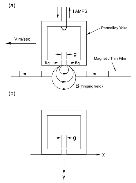
The write head is basically an electromagnet constructed of a soft magnetic permalloy yoke (the saturation field is 1 Tesla and the coercive field is Hc ∼ 4 Amps/m). This electromagnet is driven by the current through a single turn. The yoke contains a narrow gap, g, approximately 50 nm wide. The write head ”flies” over the surface of the disc at an altitude of approximately 25 nm, and the magnetic film on the disc is magnetized by the fringing field produced at the magnet gap. A field of approximately 3 times the coercive field is used to write magnetization regions into the disc magnetic film that are either parallel or antiparallel to the disc velocity. The spatial dependencies of the fringing field components near the gap are given in the Karlqvist approximation by:
\[\text{H}_{\text{x}}=\frac{\text{B}_{\text{g}}}{\mu_{0} \pi} \arctan \left[\frac{\text{y} \text{g}}{\text{x}^{2}+\text{y}^{2}-\left(\text{g}^{2} / 4\right)}\right] , \label{6.4}\]
\[\text{H}_{\text{y}}=\frac{\text{B}_{\text{g}}}{2 \pi} \ln \left[\frac{(\text{x}-\text{g} / 2)^{2}+\text{y}^{2}}{(\text{x}+\text{g} / 2)^{2}+\text{y}^{2}}\right] , \]
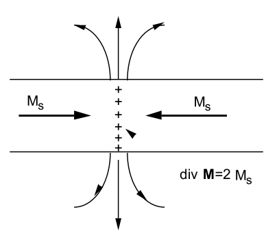
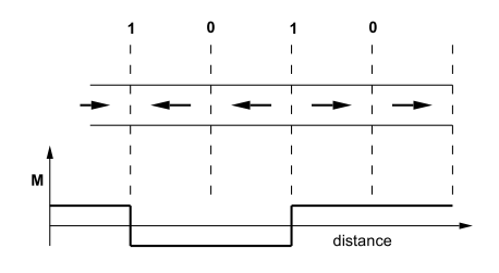
where Bg is the B-field in the middle of the gap region, and g is the gap width: the co-ordinate axes are shown in Figure (6.3.10b). Bits of information are stored as magnetization reversals (also called flux reversals). It is only at those places where the magnetizations are directed opposite to one another that the fringing field is large enough to be detected by the read head. This is illustrated in Figure (6.3.11). The absence of a flux reversal is taken to be a zero; the presence of a flux reversal is taken to be a 1. The magnetization profile for a typical run of data might look like that shown in Figure (6.3.12). In practice, each data byte of input is stored using a complex code that uses more than the nominal 8 bits per byte in order to build in the capability to detect and correct errors.
Modern read heads use a complicated structure of thin films. The magnetic field due to a magnetization change on the hard disc is detected by means of a change in resistance of a magnetoresistance element. Write and read heads are combined in a single write/read unit.
As of November 1999 IBM demonstrated a hard disc drive having the
capability to store 3.5 × 1010 bits per square inch using 522,000 bits per inch and 67,300 tracks per inch. This means that each magnetization cell was only 49 nm long by 377 nm wide. The disc spun at 10,000 revolutions per minute, the seek time was 4.9 msecs, and information was read in and out at the rate of 18 × 106 bytes per second. The uncorrected error rate was 1:108 ; after correction this error rate decreased to less than 1:1012 .
Further Reading
- S. Chikazumi, ”Physics of Magnetism”. John Wiley and Sons,New York, 1964.
- John C. Mallinson, ”The Foundations of Magnetic Recording”, Second Edition. Academic Press, San Diego, 1993.
- John C. Mallinson, ”Magneto-Resistive Heads”. Academic Press, San Diego, 1996.