
6.5: Permanent Magnet Devices
- Page ID
- 25015

Introduction
A permanent magnet (Section 2.5.4) has a residual flux density \(\overline{\mathrm{B}}_{\mathrm{r}}\) when \(\overline{\mathrm{H}}=0\) inside it, and this is the rest state of an isolated permanent magnet. In this case the magnetic energy density inside is \(\mathrm{W}_{\mathrm{m}}=\overline{\mathrm{\underline{B}}} \bullet \overline{\mathrm{H}} / 2=0\), and that outside, \(\mathrm{W}_{\mathrm{m}}=\mu_{\mathrm{o}}|\overline{\mathrm{H}}|^{2} \neq 0\). Boundary conditions (2.6.5) say \(\overline{\mathrm{B}}_{\mathrm{r} \perp}=\mu_{\mathrm{o}} \overline{\mathrm{H}}_{\mathrm{o} \perp}\), where \(\overline{\mathrm{H}}_{\mathrm{o} \perp}\) is the boundary value in air. Since \(\overline{\mathrm{H}} / /\) is continuous across an insulating boundary and \(\overline{\mathrm{H}}_{\mathrm{r}}=0\) inside a resting permanent magnet, \(\overline{\mathrm{H}}_{\mathrm{o//}}=0\) too. If an external \(\overline{\mathrm{H}}\) is applied to a permanent magnet, then \(\overline{\mathrm{B}}\) within that magnet is altered as suggested by the hysteresis diagram in Figure 2.5.3(b).
The force f [N] attracting a permanent magnet to a high-permeability material can be found using:
\[ \mathrm{f}=\mathrm{d} \mathrm{w}_{\mathrm{m}} / \mathrm{d} \mathrm{x} \]
where x is the separation between the two, as illustrated in Figure 6.5.1, and wm is the total energy in the magnetic fields [J]. The changing magnetic energy in the high-permeability material is negligible compared to that in air because: 1) boundary conditions require continuity in \(\overline{\mathrm{B}}_{\perp}\) across the boundary so that \(\overline{\mathrm{B}}_{\perp}=\mu \overline{\mathrm{H}}_{\perp}=\mu_{\mathrm{o}} \overline{\mathrm{H}}_{\mathrm{o} \perp}\), and therefore \(\mathrm{H}_{\perp} / \mathrm{H}_{\mathrm{o} \perp}=\mu_{\mathrm{o}} / \mu<<1\), and 2) \(\mathrm{W}_{\mathrm{m}} \ \left[\mathrm{Jm}^{-3}\right]=\mu|\overline{\mathrm{H}}|^{2} / 2\) where μ >> μo; thus the energy density in air is greater by ~μ/μo >> 1.
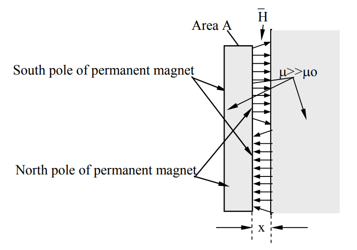
The variable magnetic energy is dominated by the energy wm in the gap, which is the energy density, \(\mathrm{W}_{\mathrm{m}}=\mu_{\mathrm{o}} \mathrm{H}_{\mathrm{gap}}^{2} / 2\), times the volume of the gap Ax, where A is the area of the magnet face and x is the gap width. Thus:
\[\mathrm{w}_{\mathrm{m}} \cong \mu_{\mathrm{o}} \mathrm{H}_{\mathrm{gap}}^{2} \mathrm{Ax} / 2 \ [\mathrm{J}]\]
Differentiating wm with respect to x yields the attractive force \(\mathrm{f} \cong \mu_{\mathrm{o}} \mathrm{H}_{\mathrm{gap}}^{2} \mathrm{A} / 2\) [N], and the force density:
\[\mathrm{F} \cong \mu_{\mathrm{o}} \mathrm{H}_{\mathrm{gap}}^{2} / 2=\mathrm{W}_{\mathrm{gap}}=\mathrm{B}_{\mathrm{gap}}^{2} / 2 \mu_{\mathrm{o}} \ \left[\mathrm{Jm}^{-3}\right]\]
This can be expressed in terms of B: \(\mathrm{F}=\mathrm{B}_{\mathrm{gap}}^{2} / 2 \mu_{\mathrm{o}}\) [Nm-2]. Note that the rest energy density inside the permanent magnet is zero, so it exerts no pressure. Most permanent magnets have magnetic flux densities B less than one Tesla (104 gauss), so a magnet this powerful with an area A = 10 cm2 (~the size of a silver dollar) would therefore apply an attractive force AF = 0.001×12/2×4π10-7 ≅ 400N (~100 pound force). A more typical permanent magnet the same size might attract a steel surface with only a 10–20 pound force.
If two equal coin-shaped permanent magnets are stacked so they stick together, then they experience primarily the attractive magnetic pressure \(\mathrm{B}_{\mathrm{gap}}^{2} / 2 \mu_{\mathrm{o}}\) [Nm-2] associated with the gap between them, and are bonded with approximately the same force density as if one of them were merely a high-permeability sheet. In this case Bgap ≅ Br , as shown in Figure 2.5.3(b).
This simple gap-based magnetic pressure model does not explain the repulsive force between two such coin magnets when one is flipped, however, for then \(\overline{\mathrm{H}}_{\mathrm{g}} \cong 0\) and wgap ≅ 0 for all small values of x, and dwg/dx is also ~0. In this case the energy of interest wT lies largely inside the magnets. This special case illustrates the risks of casually substituting simple models for the underlying physical reality captured in Maxwell’s equations, the Lorentz force law, and material characteristics.
Permanent magnets fail above their Curie temperature when the magnetic domains become scrambled. Cooling overheated permanent magnets in a strong external magnetic field usually restores them. Some types of permanent magnets can also fail at very low temperatures, and should not be used where that is a risk.
Permanent Magnet Motors
Compact high-power-density motors often incorporate permanent magnets so current is not wasted on maintenance of \(\overline{\mathrm{H}}\). For example, the stator for the rotary single-turn coil motor of Figure 6.3.1 could easily contain permanent magnets, avoiding the need for current excitation. Moreover, modern permanent magnets can provide quite intense fields, above 0.5 Tesla. In this case we should also consider the effect of the rotor currents on the stator permanent magnets, whereas in the earlier example we considered the stator fields and rotor currents as given. The incremental permeability of a permanent magnet varies with the applied H. If H is oriented to attract the stator pole and μoH > Br, then B in the permanent magnet will increase above Br (see Figure 2.5.3), where the incremental permeability approaches μo. To the extent the incremental μ > μo, some reluctance-motor torque will supplement the dominant torque studied earlier.
The permanent magnets can alternatively be placed on the rotor, avoiding the need for rotor currents or a commutator, provided the stator currents are synchronously switched instead. Clever electronics can detect the voltage fluctuations in the stator induced by the rotor and thus deduce its position, potentially avoiding the need for a separate expensive angle encoder for stator current synchronization.
Because different parts of permanent magnets see different B/H histories, and these depend in part on B/H histories elsewhere in the device, modern design of such motors or generators relies extensively on complex software tools for modeling support.
Two identical coin-shaped permanent magnets of 12-cm diameter produce 0.05 Tesla field perpendicular to their flat faces; one side is the north pole of the magnet and the other is south. What is the maximum force f attracting the magnets when placed face to face?
Solution
Using (6.5.3) yields \(\mathrm{f}=\mathrm{AB}_{\mathrm{gap}}^{2} / 2 \mu_{\mathrm{o}}=\pi(0.06)^{2}(0.05)^{2} /\left(2 \times 1.26 \times 10^{-6}\right)=11.2 \ [\mathrm{N}]\)