
6.3: Uniform circular motion
- Page ID
- 19400
As we saw in Chapter 4, “uniform circular motion” is defined to be motion along a circle with constant speed. This may be a good time to review Section 4.4 for the kinematics of motion along a circle. In particular, for the uniform circular motion of an object around a circle of radius \(R\), you should recall that:
- The velocity vector, \(\vec v\), is always tangent to the circle.
- The acceleration vector, \(\vec a\), is always perpendicular to the velocity vector, because the magnitude of the velocity vector does not change.
- The acceleration vector, \(\vec a\), always points towards the center of the circle.
- The acceleration vector has magnitude \(a=v^2/R\).
- The angular velocity, \(\omega\), is related to the magnitude of the velocity vector by \(v=\omega R\) and is constant.
- The angular acceleration, \(\alpha\), is zero for uniform circular motion, since the angular velocity does not change.
In particular, you should recall that even if the speed is constant, the acceleration vector is always non-zero in uniform circular motion because the velocity changes direction. According to Newton’s Second Law, this implies that there must be a net force on the object that is directed towards the center of the circle1 (parallel to the acceleration):
\[\begin{aligned} \sum \vec F = m\vec a\end{aligned}\]
where the acceleration has a magnitude \(a=v^2/R\). Because the acceleration is directed towards the center of the circle, we sometimes call it a “radial” acceleration (parallel to the radius), \(a_R\), or a “centripetal” acceleration (directed towards the center), \(a_c\).
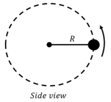
Consider an object in uniform circular motion in a horizontal plane on a frictionless surface, as depicted in Figure \(\PageIndex{1}\).
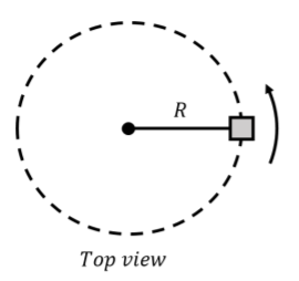
The only way for the object to undergo uniform circular motion as depicted is if the net force on the object is directed towards the center of the circle. One way to have a force that is directed towards the center of the circle is to attach a string between the center of the circle and the object, as shown in Figure \(\PageIndex{1}\). If the string is under tension, the force of tension will always be towards the center of the circle. The forces on the object are thus:
- \(\vec F_g\), its weight with magnitude \(mg\).
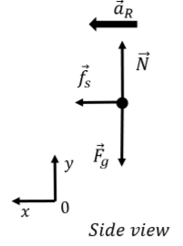
- \(\vec N\), a normal forced exerted by the surface.
- \(\vec T\), a force of tension exerted by the string.
The forces are depicted in the free-body diagram shown in Figure \(\PageIndex{2}\) (as viewed from the side), where we also drew the acceleration vector. Note that this free-body diagram is only “valid” at a particular instant in time since the acceleration vector continuously changes direction and would not always be lined up with the \(x\) axis.
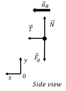
Writing out the \(x\) and \(y\) components of Newton’s Second Law:
\[\begin{aligned} \sum F_x &= T = ma_R\\[4pt] \sum F_y &= N - F_g =0\end{aligned}\]
The \(y\) component just tells us that the normal force must have the same magnitude as the weight because the object is not accelerating in the vertical direction. The \(x\) component tells us the relation between the magnitudes of the tension in the string and the radial acceleration. Using the speed of the object, we can also write the relation between the tension and the speed:
\[\begin{aligned} T &= ma_R=m\frac{v^2}{R}\\[4pt]\end{aligned}\]
Thus, we find that the tension in the string increases with the square of the speed, and decreases with the radius of the circle.
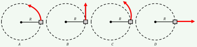
An object is undergoing uniform circular motion in the horizontal plane, when the string connecting the object to the center of rotation suddenly breaks. What path will the block take after the string broke?
- A
- B
- C
- D
- Answer
- B.
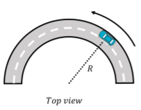
A car goes around a curve which can be approximated as the arc of a circle of radius \(R\), as shown in Figure \(\PageIndex{4}\). The coefficient of static friction between the tires of the car and the road is \(µ_{s}\). What is the maximum speed with which the car can go around the curve without skidding?
Solution
If the car is going at constant speed around a circle, then the sum of the forces on the car must be directed towards the center of the circle. The only force on the car that could be directed towards the center of the circle is the force of friction between the tires and the road. If the road were perfectly slick (think driving in icy conditions), it would not be possible to drive around a curve since there could be no force of friction. The forces on the car are:
- \(\vec F_g\), its weight with magnitude \(mg\).
- \(\vec N\), a normal force exerted upwards by the road.
- \(\vec f_s\), a force of static friction between the tires and the road. This is static friction, because the surface of the tire does not move relative to the surface of the road if the car is not skidding. The force of static friction has a magnitude that is at most \(f_s\leq\mu_sN\).
The forces on the car are shown in the free-body diagram in Figure 6.3.5.
The \(y\) component of Newton’s Second Law tells us that the normal force exerted by the road must equal the weight of the car:
\[\begin{aligned} \sum F_y = N-F_g&=0\\[4pt] \therefore N &=mg\end{aligned}\]
The \(x\) component relates the force of friction to the radial acceleration (and thus to the speed):
\[\begin{aligned} \sum F_x = f_s =ma_R&=m\frac{v^2}{R}\\[4pt] \therefore f_s &= m\frac{v^2}{R}\end{aligned}\]
The force of friction must be less than or equal to \(f_s\leq\mu_sN=\mu_smg\) (since \(N=mg\) from the \(y\) component of Newton’s Second Law), which gives us a condition on the speed:
\[\begin{aligned} f_s = m\frac{v^2}{R}&\leq\mu_smg\\[4pt] v^2 &\leq \mu_s g R\\[4pt] \therefore v &\leq \sqrt{\mu_s g R}\end{aligned}\]
Thus, if the speed is less than \(\sqrt{\mu_s g R}\), the car will not skid and the magnitude of the force of static friction, which results in an acceleration towards the center of the circle, will be smaller or equal to its maximal possible value.
Discussion
The model for the maximum speed that the car can travel around the curve makes sense because:
- The dimension of \(\sqrt{\mu_s g R}\) is speed.
- The speed is larger if the radius of the curve is larger (one can go faster around a wider curve without skidding).
- The speed is larger if the coefficient of friction is large (if the force of friction is larger, a larger radial acceleration can be sustained).
A ball is attached to a mass-less string and executing circular motion along a circle of radius \(R\) that is in the vertical plane, as depicted in Figure \(\PageIndex{6}\). Can the speed of the ball be constant? What is the minimum speed of the ball at the top of the circle if it is able to make it around the circle?
Solution
The forces that are acting on the ball are:
- \(\vec F_g\), its weight with magnitude \(mg\).
- \(\vec T\), a force of tension exerted by the string.
Figure \(\PageIndex{7}\) shows the free-body diagram for the forces on the ball at three different locations along the path of the circle.
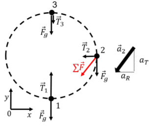
In order for the ball to go around in a circle, there must be at least a component of the net force on the ball that is directed towards the center of the circle at all times. In the bottom half of the circle (positions 1 and 2), only the tension can have a component directed towards the center of the circle.
Consider in particular the position labeled 2, when the string is horizontal and the tension is equal to \(\vec T_2\). The free-body diagram in Figure \(\PageIndex{7}\) also shows the vector sum of the weight and tension at position 2 (the red arrow labeled \(\sum \vec F\)), which points downwards and to the left. It is thus clearly impossible for the acceleration vector to point towards the center of the circle, and the acceleration will have components that are both tangential (\(a_T\)) to the circle and radial (\(a_R\)), as shown by the vector \(\vec a_2\) in Figure \(\PageIndex{7}\).
The radial component of the acceleration will change the direction of the velocity vector so that the ball remains on the circle, and the tangential component will reduce the magnitude of the velocity vector. According to our model, it is thus impossible for the ball to go around the circle at constant speed, and the speed must decrease as it goes from position 2 to position 3, no matter how one pulls on the string (you can convince yourself of this by drawing the free-body diagram at any point between points 2 and 3).
The minimum speed for the ball at the top of the circle is given by the condition that the tension in the string is zero just at the top of the trajectory (position 3). The ball can still go around the circle because, at position 3, gravity is towards the center of the circle and can thus give an acceleration that is radial, even with no tension. The \(y\) component of Newton’s Second Law, at position 3 gives:
\[\begin{aligned} \sum F_y = -F_g &= ma_y\\[4pt] \therefore a_y &=-g\end{aligned}\]
The magnitude of the acceleration is the radial acceleration, and is thus related to the speed at the top of the trajectory:
\[\begin{aligned} a_R&=-a_y=g = m\frac{v^2}{R}\\[4pt] \therefore v_{min}&=\sqrt{\frac{gR}{m}}\end{aligned}\]
which is the minimum speed at the top of the trajectory for the ball to be able to continue along the circle. The tension in the string would change as the ball moves around the circle, and will be highest at the bottom of the trajectory, since the tension has to be bigger than gravity so that the net force at the bottom of the trajectory is upwards (towards the center of the circle).
Discussion
The model for the minimum speed of the ball at the top of the circle makes sense because:
- \(\sqrt{\frac{gR}{m}}\) has the dimension of speed.
- The minimum velocity is larger if the circle has a larger radius (try this with a mass attached at the end of a string).
- The minimum velocity is larger if the mass is bigger (again, try this at home!).
Consider a ball attached to a string, being spun in a vertical circle (such as the one depicted in Figure \(\PageIndex{6}\)). If you shortened the string, how would the minimum angular velocity (measured at the top of the trajectory) required for the ball to make it around the circle change?
- It would decrease
- It would stay the same
- It would increase
- Answer
- A.
Banked curves
As we saw in Example 6.3.1, there is a maximum speed with which a car can go around a curve before it starts to skid. You may have noticed that roads, highways especially, are banked where there are curves. Racetracks for cars that go around an oval (the boring kind of car races) also have banked curves. As we will see, this allows the speed of vehicles to be higher when going around the curve; or rather, it makes the curves safer as the speed at which vehicles would skid is higher. In Example 6.3.1, we saw that it was the force of static friction between the tires of the car and the road that provided the only force with a component towards the center of the circle. The idea of using a banked curve is to change the direction of the normal force between the road and the car tires so that it, too, has a component in the direction towards the center of the circle.
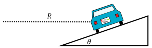
Consider the car depicted in Figure \(\PageIndex{8}\) which is seen from behind making a left turn around a curve that is banked by an angle \(\theta\) with respect to the horizontal and can be modeled as an arc from a circle of radius \(R\).
The forces exerted on the car are the same as in Example 6.3.1, except that they point in different directions. The forces are:
- \(\vec F_g\), its weight with magnitude \(mg\).
- \(\vec N\), a normal force exerted by the road, perpendicular to the surface of the road.
- \(\vec f_s\), a force of static friction between the tires and the road. This is static friction, because the surface of the tire does not move relative to the surface of the road if the car is not skidding. The force of static friction has a magnitude that is at most \(f_s\leq\mu_sN\) and is perpendicular to the normal force. The force could be either upwards or downwards, depending on the other forces on the car.
A free-body diagram for the forces on the car is shown in Figure 6.3.9, along with the acceleration (which is in the radial direction, towards the center of the circle), and our choice of coordinate system (choosing \(x\) parallel to the acceleration). The direction of the force of static friction is not known a priori and depends on the speed of the car:
- If the speed of the car is zero, the force of static friction is upwards. With a speed of zero, the radial acceleration is zero, and the sum of the forces must thus be zero. The impeding motion of the car would be to slide down the banked curve (just like a block on an incline).
- If the speed of the car is very large, the force of static friction is downwards, as the impeding motion of the car would be to slide up the bank. The natural motion of the car is to go in a straight line (Newton’s First Law). If the components of the normal force and of the force of static friction directed towards the center of the circle are too small to allow the car to turn, then the car would slide up the bank (so the impeding motion is up the bank and the force of static friction is downwards).
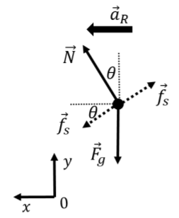
There is thus an “ideal speed” at which the force of static friction is precisely zero, and the \(x\) component of the normal force is responsible for the radial acceleration. At higher speeds, the force of static friction is downwards and increases in magnitude to keep the car’s acceleration towards the center of the circle. At some maximal speed, the force of friction will reach its maximal value, and no longer be able to keep the car’s acceleration pointing towards the center of the circle. At speeds lower than the ideal speed, the force of friction is directed upwards to prevent the car from sliding down the bank. If the coefficient of static friction is too low, it is possible that at low speeds, the car would start to slide down the bank (so there would be a minimum speed below which the car would start to slide down).
Let us model the situation where the force of static friction is identically zero so that we can determine the ideal speed for the banked curve. The only two forces on the car are thus its weight and the normal force. The \(x\) and \(y\) component of Newton’s Second Law give:
\[\begin{aligned} \label{eq:applyingnewtonslaws:carbank_x} \sum F_x &= N\sin\theta = ma_R=m\frac{v^2}{R}\nonumber\end{aligned}\]
\[\therefore N\sin\theta = m\frac{v^{2}}{R}\]
\[\begin{aligned} \label{eq:applyingnewtonslaws:carbank_y} \sum F_y &= N\cos\theta-F_g = 0\nonumber\end{aligned}\]
\[\therefore N\cos\theta =mg\]
We can divide Equation 6.3.1 by Equation 6.3.2, noting that \(\tan\theta=\sin\theta/\cos\theta\), to obtain:
\[\begin{aligned} \tan\theta &= \frac{v^2}{gR}\\[4pt] \therefore v_{ideal} &=\sqrt{gR\tan\theta}\end{aligned}\]
At this speed, the force of static friction is zero. In practice, one would use this equation to determine which bank angle to use when designing a road, so that the ideal speed is around the speed limit or the average speed of traffic. We leave it as an exercise to determine the maximal speed that the car can go around the curve before sliding out.
Inertial forces in circular motion
As you sit in a car that is going around a curve, you will feel pushed outwards, away from the center of the circle that the car is going around. This is because of your inertia (Newton’s First Law), and your body would go in a straight line if the car were not exerting a net force on you towards the center of the circle. You are not so much feeling a force that is pushing you outwards as you are feeling the effects of the car seat pushing you inwards; if you were leaning against the side of the car that is on the outside of the curve, you would feel the side of the car pushing you inwards towards the center of the curve, even if it “feels” like you are pushing outwards against the side of the car.
If we model your motion looking at you from the ground, we would include a force of friction between the car seat (or the side of the car, or both) and you that is pointing towards the center of the circle, so that the sum of the forces exerted on you is towards the center of the circle. We can also model your motion from the non-inertial frame of the car. As you recall, because this is a non-inertial frame of reference, we need to include an additional inertial force, \(\vec F_I\), that points opposite of the acceleration of the car, with magnitude \(F_I=ma_R\) (if the net acceleration of the car is \(a_R\)). Inside the non-inertial frame of reference of the car, your acceleration (relative to the reference frame, i.e. the car) is zero. This is illustrated by the diagrams in Figure \(\PageIndex{10}\).
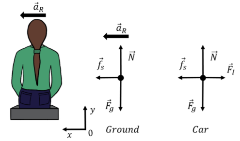
The \(y\) component of Newton’s Second Law in both frames of reference is the same:
\[\begin{aligned} \sum F_y&=N-F_g=0\\[4pt] \therefore N&=mg\end{aligned}\]
and simply tells us that the normal force is equal to the weight. In the reference frame of the ground, the \(x\) component of Newton’s Second Law gives:
\[\begin{aligned} \sum F_x &= f_s = ma_R\\[4pt] \therefore f_s &= m\frac{v^2}{R}\end{aligned}\]
In the frame of reference of the car, where your acceleration is zero and an inertial force of magnitude \(F_I=mv^2/R\) is exerted on you, the \(x\) component of Newton’s Second Law gives:
\[\begin{aligned} \sum F_x &= f_s-F_I = 0\\[4pt] \therefore f_s - m\frac{v^2}{R} &= 0\end{aligned}\]
which of course, mathematically, is exactly equivalent. The inertial force is not a real force in the sense that it is not exerted by anything. It only comes into play because we are trying to use Newton’s Laws in a non-inertial frame of reference. However, it does provide a good model for describing the sensation that we have of being pushed outwards when the car goes around a curve. Sometimes, people will refer to this force as a “centrifugal” force, which means “a force that points away from the center”. You should however remember that this is not a real force exerted on the object, but is the result of modeling motion in a non-inertial frame of reference.
Jamie is driving his tricycle around a circular pond. Jamie feels a centrifugal force with magnitude \(F_I\). If Jamie pedals twice as fast, what will be the magnitude of the centrifugal force that he experiences?
- \(\sqrt{2}F_I\)
- \(\frac{1}{2}F_I\)
- \(2F_I\)
- \(4F_I\)
- Answer
- D.
Footnotes
1. The sum of the forces is often called the “net force” on an object, and in the specific case of uniform circular motion, that net force is sometimes called the “centripetal force” - however, it is not a force in and of itself and it is always the sum of the forces that points towards the center of the circle.