
11.2: Rotational dynamics for a single particle
- Page ID
- 19437
Suppose that a single force, \(\vec F\), is acting on a particle of mass \(m\). Newton’s Second Law for the particle is then given by:
\[\begin{aligned} \vec F = m \vec a\end{aligned}\]
We can define a point of rotation such that \(\vec r\) is the position of the particle relative to that point. We can take the cross-product of \(\vec r\) with both sides of the equation in Newton’s Second Law:
\[\begin{aligned} \vec r \times \vec F &= m \vec r \times \vec a\end{aligned}\]
The left hand-side of the equation is called “the torque of \(\vec F\) relative to the point of rotation”, and is usually denoted by \(\vec \tau\):
\[\vec\tau = \vec r\times \vec F\]
The right-hand side of the equation is related to the angular acceleration vector, \(\vec \alpha\), about that point of rotation:
\[\begin{aligned} m \vec r \times \vec a = mr^2\vec\alpha\end{aligned}\]
Putting this altogether, we get:
\[\begin{aligned} \vec\tau = mr^2 \vec\alpha\end{aligned}\]
If more than one force is exerted on the particle, it is easy to show that the net torque from the net force on the particle is equal to the sum of the torques on the particle:
\[\begin{aligned} \vec r \times (\vec F_1 + \vec F_2 + \vec F_3 + \dots) &= (\vec r \times \vec F_1 + \vec r \times \vec F_2 + \vec r \times \vec F_3 + \dots) \\[4pt] \therefore \vec r \times \sum \vec F &= \sum \vec \tau = \vec \tau^{net}\end{aligned}\]
We can write “Newton’s Second Law for the rotational dynamics of a particle”:
\[\sum \vec\tau = \vec\tau ^{net}=mr^{2}\vec\alpha\]
This equation provides us an alternate formulation to Newton’s Second Law that is useful for describing the motion of a particle that is rotating. The left-hand side of the equation corresponds to the “causes of motion” (much like the sum of the forces in Newton’s Second Law), and the right-hand side of the equation to the inertia and the kinematics. A few things to note when comparing to Newton’s Second Law:
- The rotational quantities, torque and angular acceleration, are only defined with respect to a point or axis of rotation (as this determines the vector \(\vec r\)). If one chooses a different point of rotation, then the torque and angular acceleration will be different.
- The angular acceleration of a particle is proportional to the net torque exerted on it, much like the linear acceleration is proportional to the net force exerted on the particle.
- Torque about a center of rotation can be thought of as the equivalent of a force that causes things rotate about an axis that goes through the point of rotation and that is parallel to the torque/angular acceleration vectors.
- Instead of mass, it is mass times \(r^2\) that plays the role of inertia and determines how large of an angular acceleration a particle will experience for a given net torque.
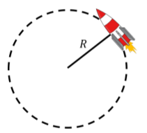
A toy rocket is attached to a string on a horizontal frictionless table, as shown in Figure \(\PageIndex{1}\). The rocket has a mass \(m\) and produces a constant force of thrust with a magnitude \(F\) that accelerates the rocket along a circle of radius \(R\) (the length of the string). If the rocket starts at rest, what distance along the circumference of the circle will the rocket have traveled after a time, \(t\)?
Solution
We can model the rocket as a point particle of mass \(m\) with the following forces exerted on it:
- \(\vec F\), the thrust of the rocket, always acting tangent to the circle.
- \(\vec T\), the force of tension in the string, always acting towards the center of the circle.
- \(\vec F_g\), the rocket’s weight, acting into the page, with magnitude \(mg\).
- \(\vec N\), a normal force exerted by the table, out of the page, with magnitude \(mg\).
Because the normal force and the weight are equal in magnitude and opposite in direction, the net force will be the sum of the force of thrust and the force of tension, which are always perpendicular to each other. Thinking about this with Newton’s Second Law, we could model the force of thrust as increasing the speed of the particle, while the force of tension keeps the rocket moving in a circle (it can do no work to increase the speed, since it is always perpendicular to the motion).
We can also think about this in terms of torques and angular acceleration about the center of the circle. The thrust will result in a net torque about the center of rotation, which will lead to the rocket having an angular acceleration. By determining the angular acceleration, we can then model the displacement at some time, \(t\), using kinematics. The force of tension will create no torque about the center of the circle because the force of tension is always co-linear with the position vector, \(\vec r\) (the cross-product of co-linear vectors is always zero).
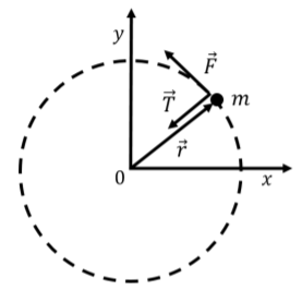
We introduce a coordinate system whose origin coincides with the center of the circle, as shown in Figure \(\PageIndex{2}\), so that \(\vec r\) corresponds to the position of the rocket relative to the origin. The force of thrust and the tension are also shown in the diagram. We choose the direction of the \(x\) axis such that the rocket was located at the intersection of the \(x\) axis and the circle at time, \(t=0\).
The net torque on the rocket about the point of rotation is given by the cross-product between the thrust force, \(\vec F\), and the position vector, \(\vec r\):
\[\begin{aligned} \vec\tau^{net} = \vec r\times\vec F\end{aligned}\]
and will point in the positive \(z\) direction (as given by the right hand rule). \(\vec r\) and \(\vec F\) are perpendicular, so the magnitude of the net torque is given by:
\[\begin{aligned} \tau^{net} = rF \sin(90^{\circ}) = RF\end{aligned}\]
where \(R\) is the magnitude of \(\vec r\). The net torque vector is thus:
\[\begin{aligned} \vec\tau^{net} = RF \hat z\end{aligned}\]
Applying the rotational version of Newton’s Second Law allows us to determine the angular acceleration:
\[\begin{aligned} \vec \tau ^{net} &= mr^2\vec\alpha\\[4pt] RF \hat z&= mR^2\vec\alpha\\[4pt] \therefore \vec \alpha &= \frac{F}{mR}\hat z\end{aligned}\]
The angular acceleration vector points in the positive \(z\) direction (as does the net torque), and indicates that the rocket is accelerating in the counter-clockwise direction about the \(z\) axis.
After a period of time \(t\), the rocket will have covered an angular displacement, \(\Delta \theta\), given by:
\[\begin{aligned} \Delta \theta &= \theta(t)-\theta_0 = \omega_0t + \frac{1}{2}\alpha t^2\\[4pt] &=\frac{1}{2}\frac{F}{mR} t^2\end{aligned}\]
The linear displacement, \(\Delta s\), that corresponds to this angular displacement is:
\[\begin{aligned} \Delta s = R \Delta\theta = \frac{1}{2}\frac{F}{m} t^2\end{aligned}\]
Discussion
The formula that we found for the total linear displacement is the same that we would have found if the particle were moving in a straight line with a net force \(F\) applied to it (as the particle would have a constant acceleration given by \(F/m\)).