
20.2: Resistors in Series and Parallel
- Page ID
- 14565

learning objectives
- Calculate the total resistance in the circuit with resistors connected in series
Overview
Most circuits have more than one component, called a resistor, that limits the flow of charge in the circuit. A measure of this limit on charge flow is called resistance. The simplest combinations of resistors are the series and parallel connections. The total resistance of a combination of resistors depends on both their individual values and how they are connected.
Series Circuits: A brief introduction to series circuit and series circuit analysis, including Kirchhoff’s Current Law (KCL) and Kirchhoff’s Voltage Law (KVL).
Resistors in Series
Resistors are in series whenever the flow of charge, or the current, must flow through components sequentially.
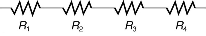
Resistors in Series: These four resistors are connected in series because if a current was applied at one end, it would flow through each resistor sequentially to the end.
shows resistors in series connected to a voltage source. The total resistance in the circuit is equal to the sum of the individual resistances, since the current has to pass through each resistor in sequence through the circuit.
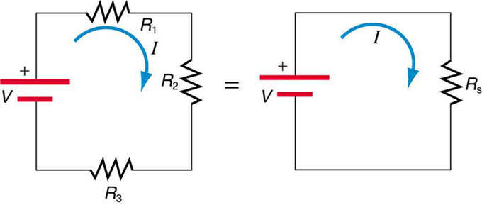
Resistors connected in a series circuit: Three resistors connected in series to a battery (left) and the equivalent single or series resistance (right).
Using Ohm ‘s Law to Calculate Voltage Changes in Resistors in Series
According to Ohm’s law, the voltage drop, V, across a resistor when a current flows through it is calculated by using the equation V=IR, where I is current in amps (A) and R is the resistance in ohms (Ω).
So the voltage drop across R1 is \(\mathrm{V_1 = IR_1}\), across R2 is \(\mathrm{V_1 = IR_2}\), and across R3 is \(\mathrm{V_1 = IR_3}\) . The sum of the voltages would equal: \(\mathrm{V = V_1 + V_2 + V_3}\), based on the conservation of energy and charge. If we substitute the values for individual voltages, we get:
\[\mathrm { V } = \mathrm { IR } _ { 1 } + \mathrm { IR } _ { 2 } + \mathrm { IR } _ { 3 }\]
or
\[\mathrm { V } = \mathrm { I } \left( \mathrm { R } _ { 1 } + \mathrm { R } _ { 2 } + \mathrm { R } _ { 3 } \right)\]
This implies that the total resistance in a series is equal to the sum of the individual resistances. Therefore, for every circuit with N number of resistors connected in series:
\[\mathrm { RN } ( \text { series } ) = \mathrm { R } _ { 1 } + \mathrm { R } _ { 2 } + \mathrm { R } _ { 3 } + \ldots + \mathrm { R } _ { \mathrm { N } }\]
Since all of the current must pass through each resistor, it experiences the resistance of each, and resistances in series simply add up.
Since voltage and resistance have an inverse relationship, individual resistors in series do not get the total source voltage, but divide it. This is indicated in an example of when two light bulbs are connected together in a series circuit with a battery. In a simple circuit consisting of one 1.5V battery and one light bulb, the light bulb would have a voltage drop of 1.5V across it. If two lightbulbs were connected in series with the same battery, however, they would each have 1.5V/2, or 0.75V drop across them. This would be evident in the brightness of the lights: each of the two light bulbs connected in series would be half as dim as the single light bulb. Therefore, resistors connected in series use up the same amount of energy as a single resistor, but that energy is divided up between the resistors depending on their resistances.
Resistors in Parallel
The total resistance in a parallel circuit is equal to the sum of the inverse of each individual resistances.
learning objectives
- Calculate the total resistance in the circuit with resistors connected in parallel
Overview
Resistors in a circuit can be connected in series or in parallel. The total resistance of a combination of resistors depends on both their individual values and how they are connected.
Parallel Circuits: A brief overview of parallel circuit analysis using VIRP tables for high school physics students.
Resistors in Parallel
Resistors are in parallel when each resistor is connected directly to the voltage source by connecting wires having negligible resistance. Each resistor thus has the full voltage of the source applied to it.
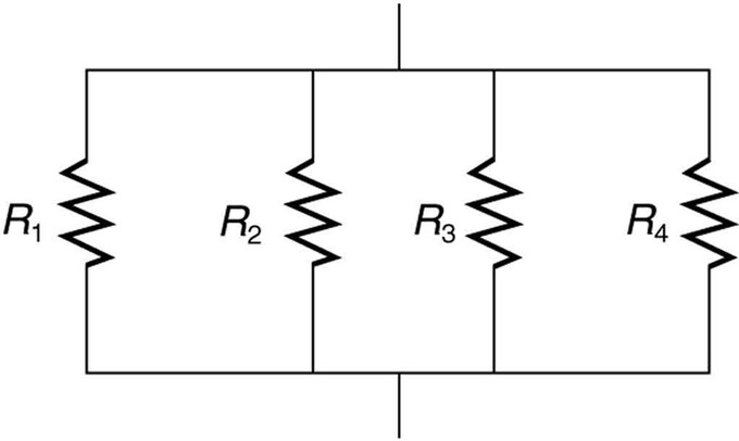
Resistors in Parallel: A parallel connection of resistors.
Each resistor draws the same current it would if it were the only resistor connected to the voltage source. This is true of the circuitry in a house or apartment. Each outlet that is connected to a appliance (the “resistor”) can operate independently, and the current does not have to pass through each appliance sequentially.
Ohm ‘s Law and Parallel Resistors
Each resistor in the circuit has the full voltage. According to Ohm’s law, the currents flowing through the individual resistors are \(\mathrm { I } _ { 1 } = \frac { \mathrm { V } } { \mathrm { R } _ { 1 } } , \mathrm { I } _ { 2 } = \frac { \mathrm { V } } { \mathrm { R } _ { 2 } },\) and \(\mathrm { I } _ { 3 } = \frac { \mathrm { V } } { \mathrm { R } _ { 3 } }\). Conservation of charge implies that the total current is the sum of these currents:
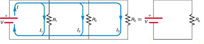
Parallel resistors: Three resistors connected in parallel to a battery and the equivalent single or parallel resistance.
\[\mathrm { I } = \mathrm { I } _ { 1 } + \mathrm { I } _ { 2 } + \mathrm { I } _ { 3 }\]
Substituting the expressions for individual currents gives:
\[\mathrm { I } = \dfrac { \mathrm { V } } { \mathrm { R } _ { 1 } } + \dfrac { \mathrm { V } } { \mathrm { R } _ { 2 } } + \dfrac { \mathrm { V } } { \mathrm { R } _ { 3 } }\]
or
\[\mathrm { I } = \mathrm { V } \left( \dfrac { 1 } { \mathrm { R } _ { 1 } } + \dfrac { 1 } { \mathrm { R } _ { 2 } } + \dfrac { 1 } { \mathrm { R } _ { 3 } } \right)\]
This implies that the total resistance in a parallel circuit is equal to the sum of the inverse of each individual resistances. Therefore, for every circuit with nn number or resistors connected in parallel,
\[\mathrm { R } _ { \mathrm { n } ( \text { parallel } ) } = \dfrac { 1 } { \mathrm { R } _ { 1 } } + \dfrac { 1 } { \mathrm { R } _ { 2 } } + \dfrac { 1 } { \mathrm { R } _ { 3 } } \ldots + \dfrac { 1 } { \mathrm { R } _ { \mathrm { n } } }\]
This relationship results in a total resistance that is less than the smallest of the individual resistances. When resistors are connected in parallel, more current flows from the source than would flow for any of them individually, so the total resistance is lower.
Each resistor in parallel has the same full voltage of the source applied to it, but divide the total current amongst them. This is exemplified by connecting two light bulbs in a parallel circuit with a 1.5V battery. In a series circuit, the two light bulbs would be half as dim when connected to a single battery source. However, if the two light bulbs were connected in parallel, they would be equally as bright as if they were connected individually to the battery. Because the same full voltage is being applied to both light bulbs, the battery would also die more quickly, since it is essentially supplying full energy to both light bulbs. In a series circuit, the battery would last just as long as it would with a single light bulb, only the brightness is then divided amongst the bulbs.
Combination Circuits
A combination circuit can be broken up into similar parts that are either series or parallel.
learning objectives
- Describe arrangement of resistors in a combination circuit and its practical implications
Combination Circuits
More complex connections of resistors are sometimes just combinations of series and parallel. This is commonly encountered, especially when wire resistances is considered. In that case, wire resistance is in series with other resistances that are in parallel.
A combination circuit can be broken up into similar parts that are either series or parallel, as diagrammed in. In the figure, the total resistance can be calculated by relating the three resistors to each other as in series or in parallel. R1 and R2 are connected in parallel in relation to each other, so we know that for that subset, the inverse of resistance would be equal to:
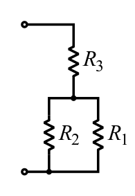
Resistor Network: In this combination circuit, the circuit can be broken up into a series component and a parallel component.
Combination Circuits: Two parallel resistors in series with one resistor.
\(\frac { 1 } { \mathrm { R } _ { 1 } } + \frac { 1 } { \mathrm { R } _ { 2 } }\) or \(\frac { \mathrm { R } _ { 1 } \mathrm { R } _ { 2 } } { \mathrm { R } _ { 1 } + \mathrm { R } _ { 2 } }\)
R3 is connected in series to both R1 and R2, so the resistance would be calculated as:
\[\mathrm { R } = \dfrac { \mathrm { R } _ { 1 } \mathrm { R } _ { 2 } } { \mathrm { R } _ { 1 } + \mathrm { R } _ { 2 } } + \mathrm { R } _ { 3 } \]
Complex Combination Circuits
For more complicated combination circuits, various parts can be identified as series or parallel, reduced to their equivalents, and then further reduced until a single resistance is left, as shown in. In this figure, the combination of seven resistors was identified by being either in series or in parallel. In the initial image, the two circled sections show resistors that are in parallel.
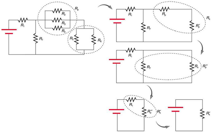
Reducing a combination circuit: This combination of seven resistors has both series and parallel parts. Each is identified and reduced to an equivalent resistance, and these are further reduced until a single equivalent resistance is reached.
Reducing those parallel resistors into a single R value allows us to visualize the circuit in a more simplified manner. In the top right image, we can see that the circled portion contains two resistors in series. We can further reduce that to another R value by adding them. The next step shows that the circled two resistors are in parallel. Reducing those highlights that the last two are in series, and thus can be reduced to a single resistance value for the entire circuit.
One practical implication of a combination circuit is that resistance in wires reduces the current and power delivered to a resistor. Combination circuit can be transformed into a series circuit, based on an understanding of the equivalent resistance of parallel branches to a combination circuit. A series circuit can be used to determine the total resistance of the circuit. Essentially, wire resistance is a series with the resistor. It thus increases the total resistance and decreases the current. If wire resistance is relatively large, as in a worn (or a very long) extension cord, then this loss can be significant. If a large current is drawn, the IR drop in the wires can also be significant.
Charging a Battery: EMFs in Series and Parallel
When voltage sources are connected in series, their emfs and internal resistances are additive; in parallel, they stay the same.
learning objectives
- Compare the resistances and electromotive forces for the voltage sources connected in the same and opposite polarity, and in series and in parallel
When more than one voltage source is used, they can be connected either in series or in parallel, similar to resistors in a circuit. When voltage sources are in series facing the same direction, their internal resistances add and their electromotive force, or emf, add algebraically. These types of voltage sources are common in flashlights, toys, and other appliances. Usually, the cells are in series in order to produce a larger total emf.
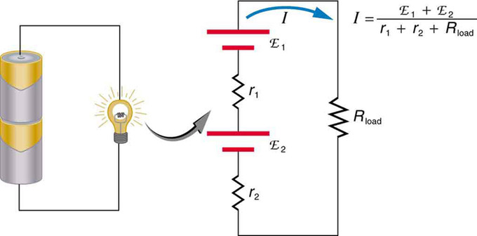
Flashlight and Bulb: A series connection of two voltage sources in the same direction. This schematic represents a flashlight with two cells (voltage sources) and a single bulb (load resistance) in series.
A battery is a multiple connection of voltaic cells. The disadvantage of series connections of cells in this manner, though, is that their internal resistances add. This can sometimes be problematic. For example, if you placed two 6v batteries in your car instead of the typical 12v single battery, you would be adding both the emfs and the internal resistances of each battery. You would therefore end up with the same 12v emf, though the internal resistance would then be doubled, causing issues for you when you want to start your engine.
But, if the cells oppose one another—such as when one is put into an appliance backwards—the total emf is less, since it is the algebraic sum of the individual emfs. When it is reversed, it produces an emf that opposes the other, and results in a difference between the two voltage sources.
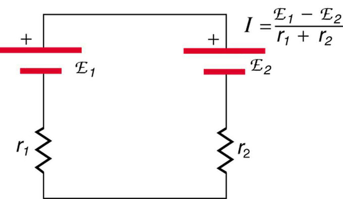
Battery Charger: This represents two voltage sources connected in series with their emfs in opposition. Current flows in the direction of the greater emf and is limited by the sum of the internal resistances. (Note that each emf is represented by script E in the figure. ) A battery charger connected to a battery is an example of such a connection. The charger must have a larger emf than the battery to reverse current through it.
When two voltage sources with identical emfs are connected in parallel and also connected to a load resistance, the total emf is the same as the individual emfs. But the total internal resistance is reduced, since the internal resistances are in parallel. Thus, the parallel connection can produce a larger current.
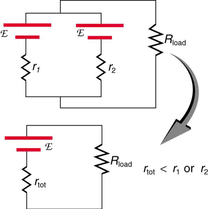
Two Identical EMFs: Two voltage sources with identical emfs (each labeled by script E) connected in parallel produce the same emf but have a smaller total internal resistance than the individual sources. Parallel combinations are often used to deliver more current.
EMF and Terminal Voltage
The output, or terminal voltage of a voltage source such as a battery, depends on its electromotive force and its internal resistance.
learning objectives
- Express the relationship between the electromotive force and terminal voltage in a form of equation
When you forget to turn off your car lights, they slowly dim as the battery runs down. Why don’t they simply blink off when the battery’s energy is gone? Their gradual dimming implies that battery output voltage decreases as the battery is depleted. The reason for the decrease in output voltage for depleted or overloaded batteries is that all voltage sources have two fundamental parts—a source of electrical energy and an internal resistance.
Electromotive Force
All voltage sources create a potential difference and can supply current if connected to a resistance. On a small scale, the potential difference creates an electric field that exerts force on charges, causing current. We call this potential difference the electromotive force (abbreviated emf). Emf is not a force at all; it is a special type of potential difference of a source when no current is flowing. Units of emf are volts.
Electromotive force is directly related to the source of potential difference, such as the particular combination of chemicals in a battery. However, emf differs from the voltage output of the device when current flows. The voltage across the terminals of a battery, for example, is less than the emf when the battery supplies current, and it declines further as the battery is depleted or loaded down. However, if the device’s output voltage can be measured without drawing current, then output voltage will equal emf (even for a very depleted battery).
Terminal Voltage
presents a schematic representation of a voltage source. The voltage output of a device is measured across its terminals and is called its terminal voltage V. Terminal voltage is given by the equation:
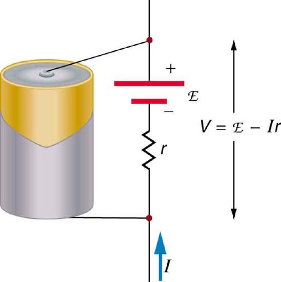
Schematic Representation of a Voltage Source: Any voltage source (in this case, a carbon-zinc dry cell) has an emf related to its source of potential difference, and an internal resistance r related to its construction. (Note that the script E stands for emf. ) Also shown are the output terminals across which the terminal voltage V is measured. Since V=emf−Ir, terminal voltage equals emf only if there is no current flowing.
\[\mathrm{V=emf−Ir.}\]
where r is the internal resistance and I is the current flowing at the time of the measurement.
I is positive if current flows away from the positive terminal. The larger the current, the smaller the terminal voltage. Likewise, it is true that the larger the internal resistance, the smaller the terminal voltage.
Key Points
- The same current flows through each resistor in series.
- Individual resistors in series do not get the total source voltage, but divide it.
- The total resistance in a series circuit is equal to the sum of the individual resistances: \(\mathrm { RN } ( \text { series } ) = \mathrm { R } _ { 1 } + \mathrm { R } _ { 2 } + \mathrm { R } _ { 3 } + \ldots + \mathrm { R } _ { \mathrm { N } }\).
- The total resistance in a parallel circuit is less than the smallest of the individual resistances.
- Each resistor in parallel has the same voltage of the source applied to it (voltage is constant in a parallel circuit).
- Parallel resistors do not each get the total current; they divide it (current is dependent on the value of each resistor and the number of total resistors in a circuit).
- More complex connections of resistors are sometimes just combinations of series and parallel.
- Various parts of a combination circuit can be identified as series or parallel, reduced to their equivalents, and then further reduced until a single resistance is left.
- Resistance in wires reduces the current and power delivered to a resistor. If the resistance in wires is relatively large, as in a worn (or a very long) extension cord, then this loss can be significant and affect power output into appliances.
- Emfs connected in the same polarity in series are additive and result in a higher total emf.
- Two emfs connected in the opposite polarity in series have a total emf equal to the difference between them, and can be used to charge the lower voltage source.
- Two voltage sources with identical emfs connected in parallel have a net emf equivalent to one emf source, however, the net internal resistance is less, and therefore produces a higher current.
Key Terms
- series: A number of things that follow on one after the other or are connected one after the other.
- resistance: The opposition to the passage of an electric current through that element.
- parallel: An arrangement of electrical components such that a current flows along two or more paths.
- combination circuit: An electrical circuit containing multiple resistors that are connected in a combination of both series and parallel connections.
- electromotive force: (EMF)—The voltage generated by a battery or by the magnetic force according to Faraday’s Law. It is measured in units of volts, not newtons, and thus, is not actually a force.
LICENSES AND ATTRIBUTIONS
CC LICENSED CONTENT, SHARED PREVIOUSLY
- Curation and Revision. Provided by: Boundless.com. License: CC BY-SA: Attribution-ShareAlike
CC LICENSED CONTENT, SPECIFIC ATTRIBUTION
- Provided by: Light and Matter. Located at: http://lightandmatter.com/lml.pdf. License: CC BY: Attribution
- OpenStax College, College Physics. September 18, 2013. Provided by: OpenStax CNX. Located at: http://cnx.org/content/m42356/latest/?collection=col11406/1.7. License: CC BY: Attribution
- series. Provided by: Wiktionary. Located at: en.wiktionary.org/wiki/series. License: CC BY-SA: Attribution-ShareAlike
- resistance. Provided by: Wikipedia. Located at: en.Wikipedia.org/wiki/resistance. License: CC BY-SA: Attribution-ShareAlike
- Series Circuits. Located at: http://www.youtube.com/watch?v=JNpnjfBFCyo. License: Public Domain: No Known Copyright. License Terms: Standard YouTube license
- OpenStax College, College Physics. November 2, 2012. Provided by: OpenStax CNX. Located at: http://cnx.org/content/m42356/latest/?collection=col11406/1.7. License: CC BY: Attribution
- OpenStax College, College Physics. November 2, 2012. Provided by: OpenStax CNX. Located at: http://cnx.org/content/m42356/latest/?collection=col11406/1.7. License: CC BY: Attribution
- Provided by: Light and Matter. Located at: http://lightandmatter.com/lml.pdf. License: CC BY: Attribution
- OpenStax College, College Physics. September 17, 2013. Provided by: OpenStax CNX. Located at: http://cnx.org/content/m42356/latest/?collection=col11406/1.7. License: CC BY: Attribution
- parallel. Provided by: Wiktionary. Located at: en.wiktionary.org/wiki/parallel. License: CC BY-SA: Attribution-ShareAlike
- resistance. Provided by: Wikipedia. Located at: en.Wikipedia.org/wiki/resistance. License: CC BY-SA: Attribution-ShareAlike
- Series Circuits. Located at: http://www.youtube.com/watch?v=JNpnjfBFCyo. License: Public Domain: No Known Copyright. License Terms: Standard YouTube license
- OpenStax College, College Physics. November 2, 2012. Provided by: OpenStax CNX. Located at: http://cnx.org/content/m42356/latest/?collection=col11406/1.7. License: CC BY: Attribution
- OpenStax College, College Physics. November 2, 2012. Provided by: OpenStax CNX. Located at: http://cnx.org/content/m42356/latest/?collection=col11406/1.7. License: CC BY: Attribution
- OpenStax College, College Physics. November 2, 2012. Provided by: OpenStax CNX. Located at: http://cnx.org/content/m42356/latest/?collection=col11406/1.7. License: CC BY: Attribution
- Parallel Circuits. Located at: http://www.youtube.com/watch?v=zAGrHdSI7fM. License: Public Domain: No Known Copyright. License Terms: Standard YouTube license
- OpenStax College, College Physics. November 2, 2012. Provided by: OpenStax CNX. Located at: http://cnx.org/content/m42356/latest/?collection=col11406/1.7. License: CC BY: Attribution
- OpenStax College, College Physics. September 17, 2013. Provided by: OpenStax CNX. Located at: http://cnx.org/content/m42356/latest/?collection=col11406/1.7. License: CC BY: Attribution
- Resistors. Provided by: Wikipedia. Located at: en.Wikipedia.org/wiki/Resistors%23Series_and_parallel_resistors. License: CC BY-SA: Attribution-ShareAlike
- combination circuit. Provided by: Wikipedia. Located at: en.Wikipedia.org/wiki/combination%20circuit. License: CC BY-SA: Attribution-ShareAlike
- parallel. Provided by: Wiktionary. Located at: en.wiktionary.org/wiki/parallel. License: CC BY-SA: Attribution-ShareAlike
- series. Provided by: Wiktionary. Located at: en.wiktionary.org/wiki/series. License: CC BY-SA: Attribution-ShareAlike
- Series Circuits. Located at: http://www.youtube.com/watch?v=JNpnjfBFCyo. License: Public Domain: No Known Copyright. License Terms: Standard YouTube license
- OpenStax College, College Physics. November 2, 2012. Provided by: OpenStax CNX. Located at: http://cnx.org/content/m42356/latest/?collection=col11406/1.7. License: CC BY: Attribution
- OpenStax College, College Physics. November 2, 2012. Provided by: OpenStax CNX. Located at: http://cnx.org/content/m42356/latest/?collection=col11406/1.7. License: CC BY: Attribution
- OpenStax College, College Physics. November 2, 2012. Provided by: OpenStax CNX. Located at: http://cnx.org/content/m42356/latest/?collection=col11406/1.7. License: CC BY: Attribution
- Parallel Circuits. Located at: http://www.youtube.com/watch?v=zAGrHdSI7fM. License: Public Domain: No Known Copyright. License Terms: Standard YouTube license
- OpenStax College, College Physics. November 2, 2012. Provided by: OpenStax CNX. Located at: http://cnx.org/content/m42356/latest/?collection=col11406/1.7. License: CC BY: Attribution
- Combination Circuits. Located at: http://www.youtube.com/watch?v=mtTlCL3pb-w. License: Public Domain: No Known Copyright. License Terms: Standard YouTube license
- OpenStax College, College Physics. November 2, 2012. Provided by: OpenStax CNX. Located at: http://cnx.org/content/m42356/latest/?collection=col11406/1.7. License: CC BY: Attribution
- Resistors. Provided by: Wikipedia. Located at: en.Wikipedia.org/wiki/Resistors. License: Public Domain: No Known Copyright
- OpenStax College, College Physics. September 17, 2013. Provided by: OpenStax CNX. Located at: http://cnx.org/content/m42357/latest/?collection=col11406/1.7. License: CC BY: Attribution
- OpenStax College, College Physics. September 17, 2013. Provided by: OpenStax CNX. Located at: http://cnx.org/content/m42357/latest/?collection=col11406/1.7. License: CC BY: Attribution
- electromotive force. Provided by: Wikipedia. Located at: en.Wikipedia.org/wiki/electromotive%20force. License: CC BY-SA: Attribution-ShareAlike
- parallel. Provided by: Wiktionary. Located at: en.wiktionary.org/wiki/parallel. License: CC BY-SA: Attribution-ShareAlike
- series. Provided by: Wiktionary. Located at: en.wiktionary.org/wiki/series. License: CC BY-SA: Attribution-ShareAlike
- Series Circuits. Located at: http://www.youtube.com/watch?v=JNpnjfBFCyo. License: Public Domain: No Known Copyright. License Terms: Standard YouTube license
- OpenStax College, College Physics. November 2, 2012. Provided by: OpenStax CNX. Located at: http://cnx.org/content/m42356/latest/?collection=col11406/1.7. License: CC BY: Attribution
- OpenStax College, College Physics. November 2, 2012. Provided by: OpenStax CNX. Located at: http://cnx.org/content/m42356/latest/?collection=col11406/1.7. License: CC BY: Attribution
- OpenStax College, College Physics. November 2, 2012. Provided by: OpenStax CNX. Located at: http://cnx.org/content/m42356/latest/?collection=col11406/1.7. License: CC BY: Attribution
- Parallel Circuits. Located at: http://www.youtube.com/watch?v=zAGrHdSI7fM. License: Public Domain: No Known Copyright. License Terms: Standard YouTube license
- OpenStax College, College Physics. November 2, 2012. Provided by: OpenStax CNX. Located at: http://cnx.org/content/m42356/latest/?collection=col11406/1.7. License: CC BY: Attribution
- Combination Circuits. Located at: http://www.youtube.com/watch?v=mtTlCL3pb-w. License: Public Domain: No Known Copyright. License Terms: Standard YouTube license
- OpenStax College, College Physics. November 2, 2012. Provided by: OpenStax CNX. Located at: http://cnx.org/content/m42356/latest/?collection=col11406/1.7. License: CC BY: Attribution
- Resistors. Provided by: Wikipedia. Located at: en.Wikipedia.org/wiki/Resistors. License: Public Domain: No Known Copyright
- OpenStax College, College Physics. November 7, 2012. Provided by: OpenStax CNX. Located at: http://cnx.org/content/m42357/latest/?collection=col11406/1.7. License: CC BY: Attribution
- OpenStax College, College Physics. November 7, 2012. Provided by: OpenStax CNX. Located at: http://cnx.org/content/m42357/latest/?collection=col11406/1.7. License: CC BY: Attribution
- OpenStax College, College Physics. November 7, 2012. Provided by: OpenStax CNX. Located at: http://cnx.org/content/m42357/latest/?collection=col11406/1.7. License: CC BY: Attribution
- OpenStax College, College Physics. September 17, 2013. Provided by: OpenStax CNX. Located at: http://cnx.org/content/m42357/latest/?collection=col11406/1.7. License: CC BY: Attribution
- Boundless. Provided by: Boundless Learning. Located at: www.boundless.com//physics/definition/terminal-voltage. License: CC BY-SA: Attribution-ShareAlike
- electromotive force. Provided by: Wikipedia. Located at: en.Wikipedia.org/wiki/electromotive%20force. License: CC BY-SA: Attribution-ShareAlike
- potential difference. Provided by: Wiktionary. Located at: en.wiktionary.org/wiki/potential_difference. License: CC BY-SA: Attribution-ShareAlike
- Series Circuits. Located at: http://www.youtube.com/watch?v=JNpnjfBFCyo. License: Public Domain: No Known Copyright. License Terms: Standard YouTube license
- OpenStax College, College Physics. November 2, 2012. Provided by: OpenStax CNX. Located at: http://cnx.org/content/m42356/latest/?collection=col11406/1.7. License: CC BY: Attribution
- OpenStax College, College Physics. November 2, 2012. Provided by: OpenStax CNX. Located at: http://cnx.org/content/m42356/latest/?collection=col11406/1.7. License: CC BY: Attribution
- OpenStax College, College Physics. November 2, 2012. Provided by: OpenStax CNX. Located at: http://cnx.org/content/m42356/latest/?collection=col11406/1.7. License: CC BY: Attribution
- Parallel Circuits. Located at: http://www.youtube.com/watch?v=zAGrHdSI7fM. License: Public Domain: No Known Copyright. License Terms: Standard YouTube license
- OpenStax College, College Physics. November 2, 2012. Provided by: OpenStax CNX. Located at: http://cnx.org/content/m42356/latest/?collection=col11406/1.7. License: CC BY: Attribution
- Combination Circuits. Located at: http://www.youtube.com/watch?v=mtTlCL3pb-w. License: Public Domain: No Known Copyright. License Terms: Standard YouTube license
- OpenStax College, College Physics. November 2, 2012. Provided by: OpenStax CNX. Located at: http://cnx.org/content/m42356/latest/?collection=col11406/1.7. License: CC BY: Attribution
- Resistors. Provided by: Wikipedia. Located at: en.Wikipedia.org/wiki/Resistors. License: Public Domain: No Known Copyright
- OpenStax College, College Physics. November 7, 2012. Provided by: OpenStax CNX. Located at: http://cnx.org/content/m42357/latest/?collection=col11406/1.7. License: CC BY: Attribution
- OpenStax College, College Physics. November 7, 2012. Provided by: OpenStax CNX. Located at: http://cnx.org/content/m42357/latest/?collection=col11406/1.7. License: CC BY: Attribution
- OpenStax College, College Physics. November 7, 2012. Provided by: OpenStax CNX. Located at: http://cnx.org/content/m42357/latest/?collection=col11406/1.7. License: CC BY: Attribution
- OpenStax College, College Physics. November 7, 2012. Provided by: OpenStax CNX. Located at: http://cnx.org/content/m42357/latest/?collection=col11406/1.7. License: CC BY: Attribution