
11.6: Moment of Inertia
- Page ID
- 19441
In order to model how an object rotates about an axis, we use Newton’s Second Law for rotational dynamics:
\[\begin{aligned} \vec\tau^{ext} = I \vec \alpha\end{aligned}\]
where \(\vec\tau^{ext}\) is the net external torque exerted on the object about the axis of rotation, \(\vec \alpha\) is the angular acceleration of the object, and \(I\) is the moment of inertia of the object (about the axis). If we consider the object as being made of many particles of mass \(m_i\) each located at a position \(\vec r_i\) relative to the axis of rotation, the moment of inertia is defined as:
\[\begin{aligned} I = \sum_i m_i r_i^2\end{aligned}\]
Consider, for example, the moment of inertia of a uniform rod of mass \(M\) and length \(L\) that is rotated about an axis perpendicular to the rod that pass through one of the ends of the rod, as depicted in Figure \(\PageIndex{1}\).
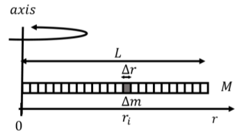
We introduce the linear mass density of the rod, \(\lambda\), as the mass per unit length:
\[\begin{aligned} \lambda = \frac{M}{L}\end{aligned}\]
We model the rod as being made of many small mass elements of mass \(\Delta m\), of length \(\Delta r\), at a location \(r_i\), as illustrated in Figure \(\PageIndex{1}\). Using the linear mass density, the mass element, \(\Delta m\), has a mass of:
\[\begin{aligned} \Delta m = \lambda \Delta r\end{aligned}\]
The rod is made of many such mass elements, and the moment of inertia of the rod is thus given by:
\[\begin{aligned} I &= \sum_i \Delta m r_i^2 =\sum_i \lambda \Delta r r_i^2\end{aligned}\]
If we take the limit in which the length of the mass element is infinitesimally small (\(\Delta r \to dr\)) the sum can be written as an integral over the dimension of the rod:
\[\begin{aligned} I &= \int_0^L\lambda r_i^2dr = \frac{1}{3}\lambda L^3 = \frac{1}{3}\left( \frac{M}{L} \right)L^3 \\[4pt] &=\frac{1}{3} ML^2\end{aligned}\]
where we re-expressed the linear mass density in terms of the mass and length of the rod. In general, we can write the moment of inertia of a continuous object as:
\[\begin{aligned} I = \int r^2 dm \end{aligned}\]
where \(dm\) is a small mass element that makes up the object, \(r\) is the distance from that mass element to the axis of rotation, and the integral is over the dimension of the object. As we did above, we would usually set up this integral so that \(dm\) is expressed in terms of \(r\) so that we can take an integral over \(r\).
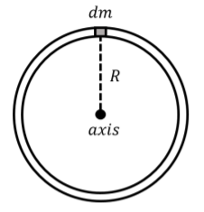
Calculate the moment of inertia of a uniform thin ring of mass \(M\) and radius \(R\), rotated about an axis that goes through its center and is perpendicular to the disk.
Solution
We take a small mass element \(dm\) of the ring, as shown in Figure \(\PageIndex{2}\).
The moment of inertia is given by:
\[\begin{aligned} I = \int dm r^2\end{aligned}\]
In this case, each mass element around the ring will be the same distance away from the axis of rotation. The value \(r^2\) in the integral is a constant over the whole ring, and so can be taken out of the integral:
\[\begin{aligned} I = \int dm r^2 = R^2\int dm\end{aligned}\]
where we used the fact that the ring has a radius \(R\), so the distance \(r\) of each mass element to the axis of rotation is \(R\). The integral:
\[\begin{aligned} \int dm\end{aligned}\]
just means “sum all of the mass elements, \(dm\)”, and is thus equal to \(M\), the total mass of the ring. The moment of inertia of the ring is thus:
\[\begin{aligned} I = R^2\int dm = MR^2\end{aligned}\]
The parallel axis theorem
The moment of inertia of a solid object can be difficult to calculate, especially if the object is not symmetric. The parallel axis theorem allows us to determine the moment of inertia of an object about an axis, if we already know the moment of inertia of the object about an axis that is parallel and goes through the center of mass of the object.
Consider an object for which we know the moment of inertia, \(I_{CM}\), about an axis that goes through the object’s center of mass. We define a coordinate system such that the origin is located at the center of mass, and the \(z\) axis is parallel to the axis about which we know the moment of inertia, as illustrated in Figure \(\PageIndex{3}\).
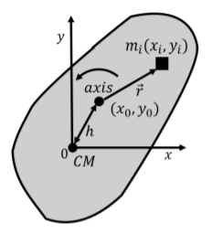
We wish to determine the moment of inertia for the object for an axis that is parallel to the \(z\) axis, but goes through a point with coordinates \((x_0,y_0)\) located a distance \(h\) away from the center of mass. The moment of inertia about an axis parallel to the \(z\) axis and that goes through that point, \(I_h\) is given by:
\[\begin{aligned} I_h = \sum_i m_i r_i^2\end{aligned}\]
where \(m_i\) is a mass element of the object located at a distance \(r_i\) from the axis of rotation. If the mass element is located at a position \((x_i,y_i)\) relative to the center of mass, we can write the distance \(r_i\) in terms of the position of the mass element, and of the position of the axis of rotation:
\[\begin{aligned} r_i^2 = (x_i-x_0)^2+(y_i-y_0)^2 = x_i^2-2x_ix_0+x_0^2+y_i^2-2y_iy_0+y_0^2\end{aligned}\]
Note that:
\[\begin{aligned} x_0^2 + y_0^2 = h^2\end{aligned}\]
The moment of inertia, \(I_h\), can thus be written as:
\[\begin{aligned} I_h &= \sum_i m_i r_i^2 =\sum_i (m_i(x_i^2+ y_i^2)-2x_0m_ix_i-2y_0m_iy_i+m_ih^2)\\[4pt] &=\sum_i m_i(x_i^2+ y_i^2) + h^2\sum_i m_i - 2x_0 \sum_im_ix_i- 2y_0 \sum_im_iy_i\end{aligned}\]
where we broke the sum up into several sums, and factored constant terms (\(h\), \(x_0\), \(y_0\)) out of the sums, since these constants do not depend on which mass element we are considering. The first term is the moment of inertia about the center of mass, since \(x_i^2+y_i^2\) is the distance to the center of mass. The second term is \(h^2\) times the total mass of the object, since the sum of all the \(m_i\) is just the mass, \(M\), of the object. Now consider the term:
\[\begin{aligned} -2x_0 \sum_im_ix_i\end{aligned}\]
The sum, \(\sum m_i x_i\) is the numerator in the definition of the \(x\) coordinate of the center of mass! The sum is thus zero, because we choose the origin to be located at the center of mass. The last two terms in the sum are thus identically zero, because they correspond to the \(x\) and \(y\) coordinates of the center of mass!
We can thus write the parallel axis theorem:
\[I_{h}=I_{CM}+Mh^{2}\]
where \(I_{CM}\) is the moment of inertia of an object of mass \(M\) about an axis that goes through the center of mass and, \(I_h\), is the moment of inertia about a second axis that is parallel to the first and a distance \(h\) away.
In the previous section, we calculated the moment of inertia of a rod of length \(L\) and mass \(M\) through an axis that is perpendicular to the rod and through one of its ends, and found that it was given by:
\[\begin{aligned} I=\frac{1}{3}ML^2\end{aligned}\]
What is the moment of inertia of the rod about an axis that is perpendicular to the rod and goes through its center of mass?
Solution
In this case, we know the moment of inertia through an axis that does not go through the center of mass. The center of mass is located a distance \(h=L/2\) away from the point about which we know the moment of inertia, \(I_h\).
Using the parallel axis theorem, we can find the moment of inertia through the center of mass:
\[\begin{aligned} I_{CM} &= I_h - Mh^2\\[4pt] &=\frac{1}{3}ML^2 - M \left( \frac{L}{2}\right)^2 = \frac{1}{12}ML^2\end{aligned}\]
Discussion
We find that the moment of inertia about the center of mass is smaller than the moment of inertia about the end of the rod. This makes sense because when rotating the rod about its end, more of its mass is further away from the axis of rotation, which results in a larger moment of inertia.