
18.5: Capacitors
- Page ID
- 19499
Capacitors are common electronic devices that are used to store electric charge for a variety of applications. A capacitor is usually constructed with two conducting plates (called “terminals” or “electrodes”) separated by either air or an insulating material.
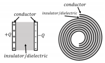
Figure \(\PageIndex{1}\) shows two examples of capacitors. The left panel shows a “parallel plate” capacitor, consisting of two conducting plates separated by air or an insulator. The plates are conducting in order for one to be able to easily add and remove charge to the plates. The plates always hold equal and opposite charges. The right panel shows a more practical implementation of a capacitor that could be used in a circuit, which is simply made by “rolling up” a parallel plate capacitor (with an insulator instead of air separating the plates so that they do not touch).
Capacitance
As long as the quantities of charge involved are not too large, it has been observed that the amount of charge, \(Q\), that can be stored on a capacitor1, is linearly proportional to the potential difference, \(\Delta V\), between the two plates:
\[\begin{aligned} Q\propto \Delta V\end{aligned}\]
\[Q=C\Delta V\]
The constant of proportionality, \(C\), between charge and potential difference across the capacitor (usually called voltage across the capacitor) is called “capacitance”, and has S.I. units of “Farads”, \(F\). The capacitance of a particular capacitor is a measure of how much charge it can hold at given voltage and depends on the geometry of the capacitor as well as the material between the terminals. If too much charge is placed on a capacitor, the material between the two plates will break down, and a spark will usually damage the capacitor as well as discharge it.
We can easily calculate the capacitance of a parallel plate capacitor. We model the capacitor as being made of two conducting plates, each with area, \(A\), separated by a distance, \(L\), and holding charge with magnitude, \(Q\). The surface charge density on one of the plates, \(\sigma\), is just given by:
\[\begin{aligned} \sigma =\frac{Q}{A}\end{aligned}\]
In Example 18.2.3, we found an expression for the potential difference between two parallel plates:
\[\begin{aligned} \Delta V &= \frac{\sigma}{\epsilon_0}L=\left(\frac{L}{A\epsilon_0}\right)Q\end{aligned}\]
Comparing with, \(Q=C\Delta V\), the capacitance of the parallel plate capacitor is found to be:
\[\begin{aligned} C=\epsilon_0\frac{A}{L}\end{aligned}\]
It makes sense that the capacitance, the amount of charge that can be stored at a given voltage, increases if the plates have a larger area (more space for charges), and decreases if the plates are further apart (smaller electric field).
Capacitors are used in many touch screens. For example, these might be made of glass (an insulator), with a thin metal coating that one touches to interact with the screen (one of the plates). As you touch the metal plate, you effectively change the capacitance of the screen, which can be sensed and modeled to determine the location of your finger(s). Modern touch screen have many capacitors built directly into the screen, and function based on this principle.
A capacitor holds \(0.2\text{C}\) of charge when it has a potential difference of \(500\text{V}\) between its plates. If the same capacitor holds \(0.15\text{C}\) of charge, what is the potential difference between its plates?
- \(375\text{ V}\).
- \(500 \text{V}\).
- \(75\text{ V}\).
- \(150\text{ V}\).
- Answer
-
Dielectric materials
In practice, capacitors always have an insulating material between the two plates. The material is chosen to have a higher breakdown voltage than air, so that more charges can be stored before a breakdown occurs. It has also been experimentally observed that the capacitance increases with certain materials, so called “dielectric materials”. A dielectric material has a “dielectric constant”, \(K\), defined to be the amount by which the capacitance increases:
\[\begin{aligned} C=KC_0\end{aligned}\]
where \(C\) is the capacitance with the material in place, and \(C_0\) is the capacitance when there is vacuum between the plates (the dielectric constant of air is very close to 1). Often, rather than the dielectric constant, one uses the “permittivity”, \(\epsilon\), of a material:
\[\begin{aligned} \epsilon=K\epsilon_0\end{aligned}\]
based on the permittivity of free space, \(\epsilon_0\). The capacitance of a parallel plate capacitor, with a material that has permittivity, \(\epsilon\), is thus given by:
\[\begin{aligned} C=K\epsilon_0\frac{A}{L}=\epsilon\frac{A}{L}\end{aligned}\]
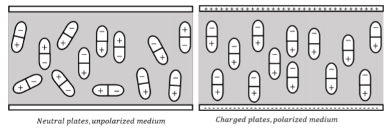
Dielectrics materials are made of molecules that can be polarized (as water), namely molecules that have a non-zero electric dipole moment. When the dielectric material is placed between the plates, the dipoles inside the material align themselves with the electric field from the plates. This leads to a second electric field, from the dipoles, in the opposite direction of the field from the plates, thus reducing the total electric field between the plates. This, in turn, allows more charges to be held on the plate for a given voltage. This is illustrated in Figure \(\PageIndex{2}\)
Note that, in a dielectric material with permittivity, \(\epsilon\), Gauss’ Law is modified to read:
\[\begin{aligned} \oint \vec E\cdot d\vec A=\frac{Q^{enc}}{\epsilon}\end{aligned}\]
where the permittivity of free space, \(\epsilon_0\), is simply replaced with the permittivity of the material, \(\epsilon\).
Energy stored in a capacitor
The charges stored on a capacitor have electrical potential energy: if one were to place a conductor between the plates, charges would immediately conduct from one plate to the other and gain kinetic energy. We can model the amount of energy stored on the capacitor by considering how much work it takes to place the charges on the capacitor.
Imagine that both plates on the capacitor start with a charge of magnitude, \(q\). We then remove an infinitesimal negative charge, with magnitude \(dq\), from the positive plate and place it on the negative plate. This required work, since we had to pull this negative charge away from the positive plate. If the potential difference across the plates is \(\Delta V\), then we had to do an amount of work given by:
\[\begin{aligned} dW = \Delta Vdq\end{aligned}\]
since the charge \(dq\) has now gained potential energy, \(\Delta Vdq\). The potential difference is however dependent on the (constant) capacitance of the capacitor, and the amount of charge, \(q\), already stored on the plates:
\[\begin{aligned} q &= C\Delta V\\[4pt] \therefore \Delta V&=\frac{q}{C}\end{aligned}\]
In order to determine the work required to transfer a total amount of charge, \(Q\), we sum the work in transferring each infinitesimal charge, \(dq\):
\[\begin{aligned} W=\int dW=\int_0^Q \Delta Vdq=\int_0^Q \frac{q}{C}dq=\frac{1}{2}\frac{Q^2}{C}\end{aligned}\]
Thus, the total potential energy that is stored on a capacitor is given by:
\[\begin{aligned} U = \frac{1}{2}\frac{Q^2}{C} = \frac{1}{2}Q(\Delta V)^2=\frac{1}{2}Q\Delta V\end{aligned}\]
where we made use of \(Q=C\Delta V\) to show the formula with different choices of variables. In either case, the amount of energy that is stored increases with the amount of charge, the capacitance, and the voltage across the capacitor. Capacitors are useful because this energy can be released quickly, as in the bright flash of light required for flash photography.
Footnotes
1. This is the amount of charge on one of the plates. As a whole, the capacitor is neutral.