
4.2: Dynamics
- Page ID
- 32439

Concepts and Principles
We are now prepared to investigate forces that are free to vary in magnitude and direction. However, you may recall that at no time in the explanation of Newton’s laws was the conversation restricted to either constant acceleration or constant force. In fact, Newton’s laws are completely valid regardless of the nature of the forces acting on an object, or its acceleration.4 Thus, the relation
\[\Sigma F=m a \nonumber\]
remains valid, and is still the central relationship in the study of mechanics.
Note
4 Actually, Newton’s Second Law is known to be inadequate to explain phenomenon occurring at extremely high speeds or at extremely small distances. The speeds must be comparable to the speed of light or the distances must be comparable to the size of the atom for these effects to be noticeable.
Analysis Tools
Time-Dependent Forces
A 2.0 kg toy rocket is fitted with an engine that provides a thrust roughly modeled by the function F(t) = (60 N/s) t - (15 N/s2) t2, for 0 < t < 4.0 s, and zero thereafter. The rocket is launched directly upward.
Of course, the first step to analyzing any situation involving forces is to construct a free-body diagram. Below is a free-body diagram for the rocket during the time interval 0 < t < 4.0 s.
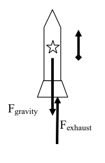
Given that you are not presented with information pertaining to the frictional force acting on the rocket, you must analyze the rocket’s trajectory in a hypothetical, friction-free environment.
From Newton’s second law:
\[\begin{aligned}
&\Sigma F=m a \\
&F_{\text {exhaust }}-F_{\text {gravity }}=m a \\
&60 t-15 t^{2}-2(9.8)=2 a \\
&-7.5 t^{2}+30 t-9.8=a
\end{aligned} \nonumber\]
Thus, the acceleration of the rocket is not constant, and the velocity and position of the rocket must be determined by integrating the acceleration.
Before we do this, however, note that the acceleration of the rocket is initially directed downward. (At t = 0s, a = -9.8 m/s2.) This is because the supporting force exerted on the rocket by the launch platform has been ignored. This force would hold the rocket in place until the force of the exhaust gases on the rocket is equal to, and then exceeds, the force of gravity on the rocket. In reality, the acceleration of the rocket is zero until Fexhaust = Fgravity. This occurs when:
\[\begin{aligned}
&F_{\text {exhaust }}=F_{\text {gravity }} \\
&60 t-15 t^{2}=2(9.8) \\
&-15 t^{2}+60 t-19.6=0 \\
&t=0.36 \mathrm{~s}
\end{aligned} \nonumber\]
The correct motion information is tabulated below.
| Event 1: The engine is ignited | Event 2: Rocket leaves the pad | Event 3: The thrust ends | Event 4: The rocket reaches its apex |
|---|---|---|---|
| t1 = 0 s | t2 = 0.36 s | t3 = 4.0 s | t4 = |
| r1 = 0 m | r2 = 0 m | r3 = | r4 = |
| v1 = 0 m/s | v2 = 0 m/s | v3 = | v4 = 0 m/s |
| a1 = 0 m/s2 | a2 = 0 m/s2 | a3 = | a4 = -9.8 m/s2 |
Between event 2 and 3, the rocket’s acceleration is given by the function above:
\(a(t)=-7.5 t^{2}+30 t-9.8\)
We can integrate the acceleration to determine the velocity,
\(\begin{aligned}
&v(t)=\int a(t) d t \\
&v(t)=\int\left(-7.5 t^{2}+30 t-9.8\right) d t \\
&v(t)=-2.5 t^{3}+15 t^{2}-9.8 t+C
\end{aligned}\)
Since we know v = 0 m/s when t = 0.36 s, we can determine the integration constant:
\(\begin{aligned}
&v(0.36)=-2.5(0.36)^{3}+15(0.36)^{2}-9.8(0.36)+C=0 \\
&C=1.70 \mathrm{~m} / \mathrm{s}
\end{aligned}\)
Therefore,
\(v(t)=-2.5 t^{3}+15 t^{2}-9.8 t+1.7\)
and when the thrust ends, at t3 = 4.0 s, v3 = 42.5 m/s.
To find the position of the rocket when the thrust ends, integrate the velocity function:
\(\begin{aligned}
&r(t)=\int v(t) d t \\
&r(t)=\int\left(-2.5 t^{3}+15 t^{2}-9.8 t+1.7\right) d t \\
&r(t)=-0.625 t^{4}+5 t^{3}-4.9 t^{2}+1.7 t+D
\end{aligned}\)
Since we know r = 0 m when t = 0.36 s, we can determine the integration constant:
\(\begin{aligned}
&r(0.36)=-0.625(0.36)^{4}+5(0.36)^{3}-4.9(0.36)^{2}+1.7(0.36)+D=0 \\
&D=-0.178
\end{aligned}\)
Therefore,
\(r(t)=-0.625 t^{4}+5 t^{3}-4.9 t^{2}+1.7 t-0.178\)
and when the thrust ends, at t3 = 4.0 s, r3 = 88.2 m.
Between event 3 and 4 the acceleration is constant, so we can use our constant-acceleration kinematic equations:
\[ \begin{array}{ll}
\mathrm{v}_{4}=\mathrm{v}_{3}+\mathrm{a}_{34}\left(\mathrm{t}_{4}-\mathrm{t}_{3}\right) & \mathrm{r}_{4}=\mathrm{r}_{3}+\mathrm{v}_{3}\left(\mathrm{t}_{4}-\mathrm{t}_{3}\right)+1 / 2 \ \mathrm{a}_{34}\left(\mathrm{t}_{4}-\mathrm{t}_{3}\right)^{2} \\
0=42.5+(-9.8)\left(\mathrm{t}_{4}-4\right) & \mathrm{r}_{4}=88.2+42.5(8.34-4)+1 / 2 \ (-9.8)(8.34-4)^{2} \\
\mathrm{t}_{4}=8.34 \mathrm{~s} . & \mathrm{r}_{4}=180 \mathrm{~m}
\end{array} \nonumber \]
Thus, the rocket would achieve a maximum height of 180 m in a friction-free environment.
Applying Newton's Second Law to Circular Motion
Investigate the situation below, in which an object travels on a curved path.Note
During a high speed auto chase in San Francisco, a 1745 kg police cruiser traveling at constant speed loses contact with the road as it goes over the crest of a hill with radius of curvature 80 m.
A free-body diagram for the car at the instant it’s at the crest of the hill is sketched below.
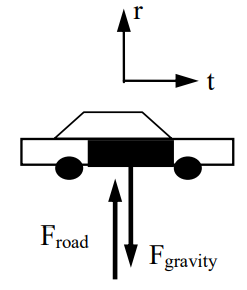
It’s doubtful that the shape of the hill that the car travels on is circular. However, at every point on the hill we can approximate the path of the car with a circle of appropriate radius. This “instantaneous circular path” has a radius equal to the given radius of curvature. Any curved path can be approximated as a series of circular paths. Therefore, since the car is traveling along a circular path, it’s best to analyze the situation using polar coordinates. Remember, in polar coordinates the radial direction points away from the center of the circular path.
In general you should apply Newton’s second law independently in the radial (r) and tangential (t) directions, although since the cruiser is moving at constant speed there is no acceleration in the tangential direction and therefore no net force in the tangential direction.
\[\begin{aligned} & \qquad\underline{\mathbf { r-direction }}\\ &\begin{aligned} &\Sigma F=m a \\ &F_{\text {road }}-F_{\text {gravity }}=m a_{r} \\ &F_{\text {road }}-F_{\text {gravity }}=m\left(-R \omega^{2}\right) \end{aligned} \end{aligned} \nonumber\]
Since the cruiser loses contact with the road, Froad = 0 N.
\[\begin{aligned}
&0-1745(9.8)=-1745(80) \omega^{2} \\
&\omega=0.35 \mathrm{rad} / \mathrm{s}
\end{aligned} \nonumber\]
Since v = R \(\omega\),
\[\begin{aligned}
&v=(80 \mathrm{~m})(0.35 \mathrm{rad} / \mathrm{s}) \\
&v=28 \mathrm{~m} / \mathrm{s}
\end{aligned} \nonumber\]
For the car to lose contact with the road, it must be traveling at a speed of 28 m/s or greater when it reaches the crest of the hill. At lower speeds, the car would remain in contact with the road.
Since it is often useful to directly relate the radial acceleration of an object to its velocity, let’s construct a direct relationship between these two variables:
\[\begin{aligned}
&a_{r}=-R \omega^{2} \\
&a_{r}=-R\left(\frac{v}{R}\right)^{2} \\
&a_{r}=-\frac{v^{2}}{R}
\end{aligned} \nonumber\]
This relationship, although mathematically equivalent to \( a_{r}=-R \omega^{2}\), is in a more “useful” form.
Another Circular Motion Scenario
A 950 kg car, traveling at a constant 30 m/s, safely makes a lefthand-turn with radius of curvature 75 m.
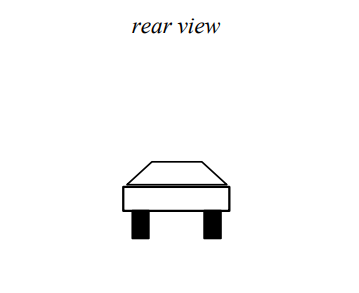
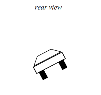
First, let's draw a pair of free-body diagrams for the car, a side-view (on the left) and a rearview (on the right)
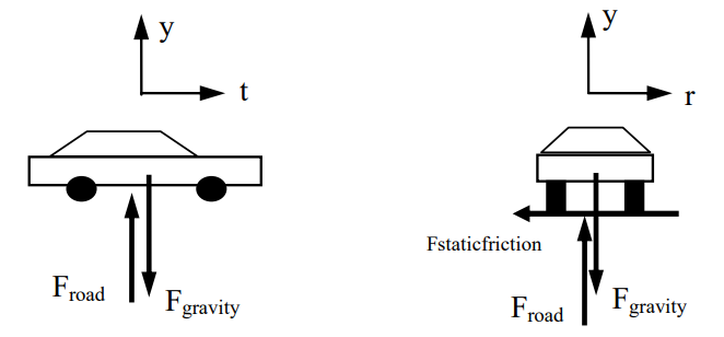
The free-body diagram on the left is a side-view of the car. Notice that the upward direction is the y-direction, and the forward direction, tangent to the turn, is the t-direction.
The free-body diagram on the right is a rear-view of the car. This is what you would see if you stood directly behind the car. Notice that the upward direction is still the y-direction, and the horizontal direction, perpendicular to the direction of travel and hence directed radially outward, is the r-direction. The frictional force indicted is perpendicular to the tread on the tire. This force causes the car to accelerate toward the center of the turn. Remember, if the car is going to travel along a circular path, it must have an acceleration directed toward the center of the circle. Something has to be supplying the force that creates this acceleration. This something is the static friction between the tire and the road that acts to prevent the car from sliding out of the turn. Since the car has no velocity in the radial direction, the frictional force that points in this direction must be static!
Now that we have all that straightened out (maybe), let's apply Newton's Second Law.
\[\begin{array}{ll} \underline{\mathbf{y-direction }} && \underline{\mathbf { r-direction }} \\ \Sigma F=m a && \Sigma F=m a \\ F_{\text {road }}-F_{\text {gravity }}=m a_{y} && -F_{\text {staticfiction }}=m a_{r} \\ F_{\text {road }}-950(9.8)=950(0) && -F_{\text {staticfiction }}=m\left(-\frac{v^{2}}{R}\right) \\ F_{\text {road }}=9310 N && F_{\text {staticfriction }}=950\left(\frac{30^{2}}{75}\right) \\ && F_{\text {staticfriction }}=11400 \mathrm{~N} \end{array} \nonumber\]
Thus, to safely make this turn requires at least 11400 N of static friction. Using this value, I should be able to compute the minimum coefficient of friction necessary for the car to safely round this turn at this speed.
\[\begin{aligned}
&F_{\text {staticfriction }} \leq \mu_{s} F_{\text {road }} \\
&11400 \leq \mu_{s}(9310) \\
&\mu_{s} \geq 1.22
\end{aligned} \nonumber\]
Although this is a large value for the coefficient of static friction, it is an attainable value for a sports car with performance tires.
Activities
Six artificial satellites of mass, m, circle a space station at constant speed, v.
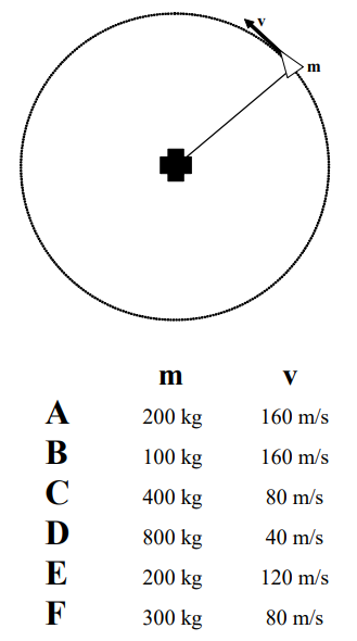
a. If the distance between the space station and the satellites is the same for all satellites, rank the magnitude of the net force acting on each satellite.
Largest 1. _____ 2. _____ 3. _____ 4. _____ 5. _____ 6. _____ Smallest
_____ The ranking cannot be determined based on the information provided.
Explain the reason for your ranking:
b. If the period is the same for all satellites, rank the magnitude of the net force acting on each satellite.
Largest 1. _____ 2. _____ 3. _____ 4. _____ 5. _____ 6. _____ Smallest
_____ The ranking cannot be determined based on the information provided.
Explain the reason for your ranking:
Six artificial satellites of mass, m, circle a space station at distance, R.
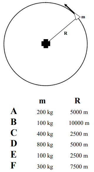
a. If the tangential speed is the same for all satellites, rank the magnitude of the net force acting on each satellite.
Largest 1. _____ 2. _____ 3. _____ 4. _____ 5. _____ 6. _____ Smallest
_____ The ranking cannot be determined based on the information provided.
Explain the reason for your ranking:
b. If the period is the same for all satellites, rank the magnitude of the net force acting on each satellite.
Largest 1. _____ 2. _____ 3. _____ 4. _____ 5. _____ 6. _____ Smallest
_____ The ranking cannot be determined based on the information provided.
Explain the reason for your ranking:
Six rollercoaster carts pass over semi-circular “bumps”. The mass of each cart (including passenger), M, and the force of the track on the cart at the apex of each bump, F, are given below.
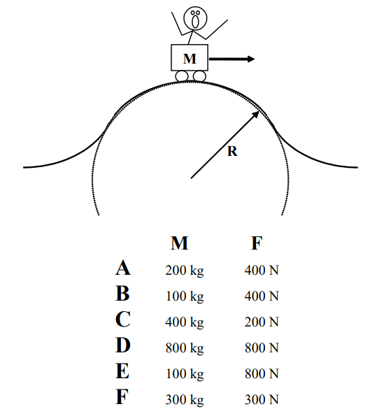
a. If the radius of each bump is the same, rank the speed of the cart as it passes over the apex of the bump.
Largest 1. _____ 2. _____ 3. _____ 4. _____ 5. _____ 6. _____ Smallest
_____ The ranking cannot be determined based on the information provided.
Explain the reason for your ranking:
b. If the speed of each cart is the same at the apex, rank the radius of each bump.
Largest 1. _____ 2. _____ 3. _____ 4. _____ 5. _____ 6. _____ Smallest
_____ The ranking cannot be determined based on the information provided.
Explain the reason for your ranking:
A rollercoaster track has six semi-circular “dips” with different radii of curvature, R. The rollercoaster cart rides through each dip at a different speed, v.
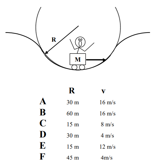
Rank the magnitude of the force of the rollercoaster track on the cart at the bottom of each dip.
Largest 1. _____ 2. _____ 3. _____ 4. _____ 5. _____ 6. _____ Smallest
_____ The ranking cannot be determined based on the information provided.
Explain the reason for your ranking:
A rollercoaster track has a semi-circular “bump” of radius of curvature R. A rollercoaster cart (including passenger) of total mass M rides over the bump.
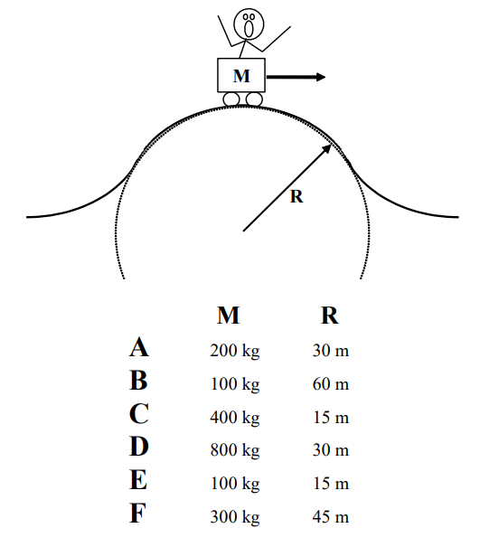
Rank the minimum speed necessary for the cart to momentarily lose contact with the track at the top of the bump
Largest 1. _____ 2. _____ 3. _____ 4. _____ 5. _____ 6. _____ Smallest
_____ The ranking cannot be determined based on the information provided.
Explain the reason for your ranking:
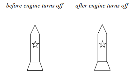
A 100 kg rocket is fired vertically upward. Its engine supplies an upward force of magnitude F = (5000 – 5.0t2) N (where t is in seconds) until F = 0 N, then the engine shuts off.
Motion Information
| Event 1: | Event 2: | Event 3: |
|---|---|---|
| t1 = | t2 = | t3 = |
| r1 = | r2 = | r3 = |
| v1 = | v2 = | v3 = |
| a1 = | a2 = | a3 = |
Free-Body Diagrams
Mathematical Analysis20
A 75 kg rocket is launched directly upward. The force on the rocket due to its engine increases from 0 N to 5000 N over 8.0 s as a linear function of time. The thrust then drops to zero almost instantaneously.
Motion Information
| Event 1: | Event 2: | Event 3: | Event 4: |
|---|---|---|---|
| t1 = | t2 = | t3 = | t4 = |
| r1 = | r2 = | r3 = | r4 = |
| v1 = | v2 = | v3 = | v4 = |
| a1 = | a2 = | a3 = | a4 = |
Free-Body Diagrams
Mathematical Analysis21
A 75 kg rocket is launched directly upward. The force on the rocket due to its engine decreases from 5000 N to 0 N as a quadratic function of time. The rocket reaches a speed of 200 m/s during the time interval that its engine fires.
Motion Information
| Event 1: | Event 2: | Event 3: |
|---|---|---|
| t1 = | t2 = | t3 = |
| r1 = | r2 = | r3 = |
| v1 = | v2 = | v3 = |
| a1 = | a2 = | a3 = |
Free-Body Diagrams
Mathematical Analysis22
Two 75 kg rockets, the A-57X and the B-44ZC, are launched directly upward. The force on each rocket due to its engine decreases from 5000 N to 0 N over 8.0 s. The force on the A-57X decreases as a linear function of time while the force on the B-44ZC decreases as a quadratic function of time.
Motion Information
| A-57X | B-44ZC | ||
|---|---|---|---|
| Event 1: | Event 2: | Event 1: | Event 2: |
| t1 = | t2 = | t1 = | t2 = |
| r1 = | r2 = | r1 = | r2 = |
| v1 = | v2 = | v1 = | v2 = |
| a1 = | a2 = | a1 = | a2 = |
Force Graph
Question
Based only on the graph, which rocket is traveling faster after 8.0 s? Explain.
Mathematical Analysis23
Two 75 kg rockets, the A-57X and the B-44ZC, are launched directly upward. Both rockets reach a speed of 200 m/s after traveling for 7.1 s. The force on the A-57X due to its engine decreases to 0 N in 7.1 s as a linear function of time while the force on the B-44ZC due to its engine decreases to 0 N in 7.1 s as a quadratic function of time.
Motion Information
| A-57X | B-44ZC | ||
|---|---|---|---|
| Event 1: | Event 2: | Event 1: | Event 2: |
| t1 = | t2 = | t1 = | t2 = |
| r1 = | r2 = | r1 = | r2 = |
| v1 = | v2 = | v1 = | v2 = |
| a1 = | a2 = | a1 = | a2 = |
Force Graph
Question
Based only on the graph, which rocket’s engine exerts the larger maximum force? Explain.
Mathematical Analysis24
The horizontal thrust acting on a 270 kg rocket sled increases as a cubic function of time from 0 N to 5400 N in 4.3 s. The thrust then drops to zero almost instantaneously. The effective frictional coefficient acting between the rocket sled and the ground is (0.4, 0.3). The rocket sled starts from rest on a level surface.
Motion Information
| Event 1: | Event 2: | Event 3: | Event 4: |
|---|---|---|---|
| t1 = | t2 = | t3 = | t4 = |
| r1 = | r2 = | r3 = | r4 = |
| v1 = | v2 = | v3 = | v4 = |
| a1 = | a2 = | a3 = | a4 = |
Free-Body Diagram
Mathematical Analysis25
The horizontal thrust acting on a 270 kg rocket sled decreases from 5000 N to 0 N as a quadratic function of time. The rocket sled is traveling at 195 m/s when the engine shuts down. The effective frictional coefficient acting between the rocket sled and the ground is (0.4, 0.3). The rocket sled starts from rest on a level surface.
Motion Information
| Event 1: | Event 2: | Event 3: |
|---|---|---|
| t1 = | t2 = | t3 = |
| r1 = | r2 = | r3 = |
| v1 = | v2 = | v3 = |
| a1 = | a2 = | a3 = |
Free-Body Diagram
Mathematical Analysis26
A rollercoaster cart travels through a semicircular “bump” of radius 20 m followed by a “dip” of radius 25 m. At the apex of the bump, the 50 kg passenger momentarily loses contact with her seat, and at the bottom of the dip the bathroom scale she’s sitting on reads 1020 N.
a. How fast is the cart moving at the apex of the bump?
Free-Body Diagram
Mathematical Analysis27
b. How fast is the cart moving at the bottom of the dip?
Free-Body Diagram
Mathematical Analysis
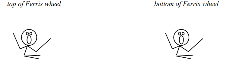
A 60 kg woman rides in a Ferris wheel of radius 16 m. In order to better understand physics, she takes along a bathroom scale and sits on it. When at the top, the scale reads 540 N. The Ferris wheel maintains the same speed throughout its motion. She checks the scale again at the bottom of the motion.
a. What is the angular speed of the Ferris wheel?
Free-Body Diagram
Mathematical Analysis28
b. What does the bathroom scale read at the bottom of the motion?
Free-Body Diagram
Mathematical Analysis
A 1.5 kg pendulum bob swings from the end of a 2 m long string. The maximum angle from vertical reached by the pendulum is 15°, and the bob reaches a speed of 1.16 m/s as it passes through its lowest point.
a. What is the force exerted on the bob by the string at the maximum angle?
Free-Body Diagram
Mathematical Analysis29
b. What is the force exerted on the bob by the string at the lowest point?
Free-Body Diagram
Mathematical Analysis
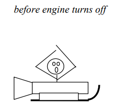
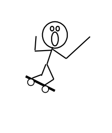
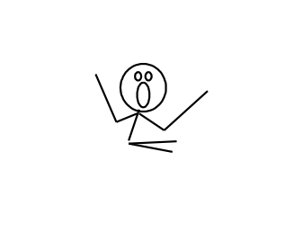
The 65 kg strange man at right is skateboarding in a halfpipe. The half-pipe is a half-circle with a radius of 5 m. At the instant shown he is 2 m from the bottom of the halfpipe, measured vertically, and is moving at 7.5 m/s. He reaches a speed of 9.5 m/s at the bottom.
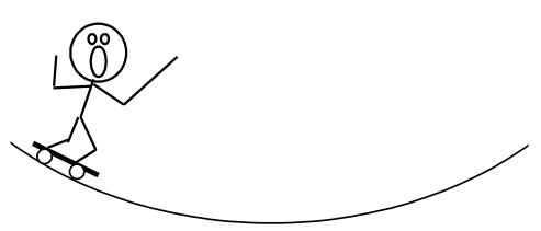
a. What is the force exerted by the skateboard on the man at the instant shown?
Free-Body Diagram
Mathematical Analysis30
b. What is the force exerted by the skateboard on the man at the bottom of the half-pipe?
Free-Body Diagram
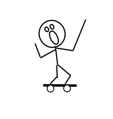
Mathematical Analysis
A 2.0 kg tether ball is attached to a vertical pole by a 1.5 m long rope. The ball is swung around the pole at an angle of 300 from vertical.
Free-Body Diagram
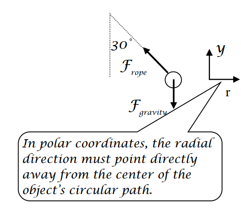
Mathematical Analysis
y-direction
\[\begin{aligned}
&\Sigma F=m a \\
&F_{\text {rope }} \cos 30-F_{\text {gravity }}=m a_{y} \\
&0.866 F_{\text {rope }}-2(9.8)=2(0) \\
&F_{\text {rope }}=22.6 N
\end{aligned} \nonumber\]
There’s no acceleration in the vertical direction if the angle of the rope is constant.
x-direction
\[\begin{aligned}
&\Sigma F=m a \\
&-F_{r o p e} \sin 30=m a_{r} \\
&-22.6(0.5)=2\left(-\frac{v^{2}}{R}\right) \\
&-11.3=2\left(-\frac{v^{2}}{1.5 \sin 30}\right) \\
&-11.3=-2.67 v^{2} \\
&v=2.06 \mathrm{~m} / \mathrm{s}
\end{aligned} \nonumber\]
The radius of the ball’s circular path is not equal to the length of the rope.
A 2.0 kg tether ball swings around a vertical pole attached to two 1.5 m long ropes, each at an angle of 300 from vertical. One rope is attached to the top of the ball and the top of the pole, the other rope is attached to the bottom of the ball and the bottom of the pole. The ball is traveling at 3.5 m/s.
Free-Body Diagram
Mathematical Analysis31
In the hammer throw, a 7.3 kg steel ball at the end of a 1.22 m wire is swung in an approximately circular path around a thrower’s head. Assume the ball is traveling at a constant speed of 7 m/s.
Free-Body Diagram
Mathematical Analysis32
A 1000 kg car rounds a 50 m radius curve at constant speed without slipping. The coefficient of friction between the car's tires and the road is (0.6,0.5).
Free-Body Diagram
Mathematical Analysis33
An 400 m radius, banked, highway curve is designed to allow cars to drive through the curve at a speed of 20 m/s and not slip, even when the road is extremely icy.
Free-Body Diagram
Mathematical Analysis34
A 100 m radius, 80 banked, highway curve has just been built. You decide to find maximum velocity with which you can drive your 1200 kg pick-up truck through this curve without sliding up or down the incline. The coefficient of friction between your enormous tires and the road is (0.7, 0.6).
Free-Body Diagram
Mathematical Analysis35
You enter an 80 m radius, 60 banked, highway curve at 30 m/s. The coefficient of friction between your tires and the road is (0.9, 0.8) .
Free-Body Diagram
Mathematical Analysis36
In an amusement park ride called the Rotor, a circular, 4.0 m radius room is spun around at high speed and then the floor is removed. The people riding the Rotor feel that they are being pressed against the wall with such a large force that they do not slide down the wall to the floor. (Obviously they do not understand physics.) The coefficient of friction between the riders and the wall is (0.6,0.5).
Free-Body Diagram
Mathematical Analysis37
A rollercoaster track has a semicircular “bump” of radius R. A passenger of mass m sits on a bathroom scale in a rollercoaster cart. Determine the reading of the bathroom scale (Fscale) as the cart goes over the top of the bump as a function of the speed of the cart (v), m, R, and g.
Free-Body Diagram
Mathematical Analysis
Questions
If R = ∞, what should Fscale equal? Does your function agree with this observation?
If v = 0 m/s, what should Fscale equal? Does your function agree with this observation?
At what speed will the rider lose contact with the scale?
A woman of mass m rides in a Ferris wheel of radius R. In order to better understand physics, she takes along a bathroom scale and sits on it. Determine the difference in scale readings between the bottom and top of the Ferris wheel (\(\Delta F_{\text {scale }}\)) as a function of the constant angular speed of the Ferris wheel (\(\omega\)), m, R, and g.
Free-Body Diagram
Mathematical Analysis
Questions
If \(\omega\) = 0 rad/s, what should \(\Delta F_{\text {scale }}\) equal? Does your function agree with this observation?
If \(\omega\) was twice as large, what would happen to \(\Delta F_{\text {scale }}\)?
A banked highway curve with radius of curvature R has just been built. With bald tires on an icy morning, determine the maximum speed (vmax) with which you can make the turn without skidding as a function of the banking angle from horizontal (\(\theta\)), the car’s mass, R, and g.
Free-Body Diagram
Mathematical Analysis
Questions
If the mass of the car was twice as large, what would happen to vmax?
If \(\theta\) = 0°, what should vmax equal? Does your function agree with this observation?
If \(\theta\) = 90°, what should vmax equal? Does your function agree with this observation?
A tether ball of mass m is attached to a vertical pole by a rope of length L. Determine the angle the rope makes with the pole (\(\theta\)) as an implicit function of the speed of the ball (v), m, L, and g.
Free-Body Diagram
Mathematical Analysis
Questions
If the mass of the ball was twice as large, what would happen to \(\theta\)?
If v = 0 m/s, what should \(\theta\) equal? Does your function agree with this observation?
If v = ∞, what should \(\theta\) equal? Does your function agree with this observation?