
6.4: Free-Body Diagrams
- Page ID
- 22235

As Figure 6.2.1 shows, trying to draw every single force acting on every single object can very quickly become pretty messy. And anyway, this is not usually what we need: what we need is to separate cleanly all the forces acting on any given object, one object at a time, so we can apply Newton’s second law, \(F_{net} = ma\), to each object individually.
In order to accomplish this, we use what are known as free-body diagrams. In a free-body diagram, a potentially very complicated object is replaced symbolically by a dot or a small circle, and all the forces acting on the object are drawn (approximately to scale and properly labeled) as acting on the dot. Regardless of whether a force is a pulling or pushing force, the convention is to always draw it as a vector that originates at the dot. If the system is accelerating, it is also a good idea to indicate the acceleration’s direction also somewhere on the diagram.
The figure below shows, as an example, a free-body diagram for block 1 in Figure \(\PageIndex{1}\), in the presence of both a nonzero acceleration and a kinetic friction force. The diagram includes all the forces, even gravity and the normal force, which were left out of the picture in Figure \(\PageIndex{1}\).
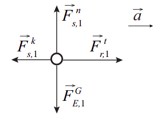
Note that I have drawn \(F^n\) and the force of gravity \(F^G_{E,1}\) as having the same magnitude, since there is no vertical acceleration for that block. If I know the value of \(\mu_k\), I should also try to draw \(F_k = \mu_k F^n\) approximately to scale with the other two forces. Then, since I know that there is an acceleration to the right, I need to draw \(F^t\) greater than \(F^k\), since the net force on the block must be to the right as well. And, if I were drawing a free-body diagram for block 2, I would have to make sure that I drew its weight, \(F^G_{E,2}\), as being greater in magnitude than \(F^t\) , since the net force on that block needs to be downwards.