
3.6: Reflection, Refraction, and Dispersion
- Page ID
- 18457

Rays
As we consider more phenomena associated with light, one of our primary concerns will be the direction that light is traveling. We already know that light, like any wave, travels in a direction perpendicular to its planes of constant phase:
Figure 3.6.1 – Light Waves Travel in Several Directions at Once
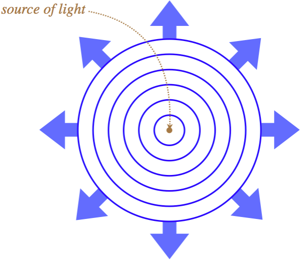
So in our wave view of light, we say that the light wave is traveling in many directions at once, but now we are going to change our perspective to that of an observer and a source. When we do that, we narrow down all the possible directions of the light wave motion to a single line, which we call a light ray. This is a directed line that originates at the source of light, and ends at the observer of the light:
Figure 3.6.2 – Source and Observer Define a Ray

Alert
When most people encounter the idea of a light ray for the first time, what they think of is a thinly-confined laser beam. This is not what is meant here! The ray has no physical meaning in terms of the confinement of light – we just use it as a simple geometrical device to link a source to an observer. Always keep in mind that the actual physical manifestation of the light is a wave that is usually traveling in many directions at once! Our use of rays will become so ubiquitous that this will be easy to forget.
Reflection
Consider a point source of light that sends out a spherical wave toward an imaginary flat plane, as in the left diagram below. When the wave reaches this plane, then according to Huygens's principle, we can look at every point on the plane and treat it as a point source for an individual wavelet (center diagram below). These wavelets are not in phase, because they are all travel different distances from the source to the plane, and when they are superposed, we know the result is what we see, which is a continued spherical wave (right diagram below).
Figure 3.6.3 – Spherical Wave Passes Through Imaginary Plane

Now suppose the plane is not imaginary, but instead reflects the wave. Every point on this plane becomes a source of a wavelet, but this time, the wave created by these wavelets is going in the opposite direction. The wavelets have the same relative phases as in the previous case, and they are completely symmetric, so they superpose to give the same total wave as before, with the exception that it is a mirror image of the case of the imaginary plane:
Figure 3.6.4 – Spherical Wave Reflects Off Plane

Thanks to the symmetry of the situation, it's not difficult to see that the reflected wave is identical to a spherical wave that has originated from a point on the opposite side of the reflecting plane, exactly the same distance from the plane as the source, and along the line that runs through the source perpendicular to the surface:
Figure 3.6.5 – Image of a Reflected Wave

Of course, there isn't actually a point light source on the other side of the reflecting plane, it's just that someone looking at the reflected light – no matter where they look from – will see the wave originating from the direction of that point. We call such a point an image of the original source of the light.
Now let's put this result in terms of light rays. To do this, we need a source and an observer, and this case, we will require also that a reflection has taken place. Once again drawing the rays perpendicular to the wave fronts, we get:
Figure 3.6.6 – Law of Reflection

It's clear from the symmetry of the situation that the angle the ray makes with the perpendicular (the horizontal dotted line) to the reflecting plane as it approaches, is the same as the angle it makes after it is reflected. This gives us the law of reflection, which states that the incoming angle (angle of incidence) equals the outgoing angle (angle of reflection):
\[\theta_i = \theta_r\]
The beauty of introducing rays is that from this point on, we can discuss sources and observers without a complicated reference to the spherical waves and Huygens's principle – we can just use the law of reflection and pure geometry.
Refraction
We saw that light waves have the capability of changing the direction of the rays associated with it through diffraction. We now consider another way that such a direction change can occur. This process, called refraction, comes about when a wave moves into a new medium. To get to the essence of this phenomenon from Huygens's principle, we don't have a symmetry trick like we did for reflection, so rather than use a point source of the light, we can look at the effect that changing the medium has on a plane wave.
We saw in Figure 3.1.2 how a plane wave propagates according to Huygens's Principle. We can't sketch every one wavelets emerging from the infinite number of points on the wavefront, but we can sketch a few representative wavelets, and if those wavelets have propagated for equal periods of time, then a line tangent to all the wavelets will represent the next wavefront. It's clear that following this procedure for a plane wave will continue the plane wave in the same direction. But now let's imagine that such a plane wave approaches a new medium from an angle, as shown in the figure below. As each point on the wave front comes in contact with the new medium, it becomes a source for a new Huygens wavelet within the medium. These wavelets will travel at a different rate than they traveled in the previous medium (in the figure, the light wave is slowing down in the new medium). This means that the distance the wave in medium #1 travels is farther than it travels in medium #2 during the same time. The effect is a bending of the direction of the plane wave in medium #2 relative to medium #1.
Figure 3.6.7 – Huygens's Principle Refracts a Plane Wave
The amount that the direction of the light ray changes when the wave enters a new medium depends upon how much the wave slows down or speeds up upon changing media. In other words, it depends upon the indices of refraction of the two media. We can actually calculate this effect by freezing the figure above and looking at some triangles:
Figure 3.6.8 – The Geometry of Refraction
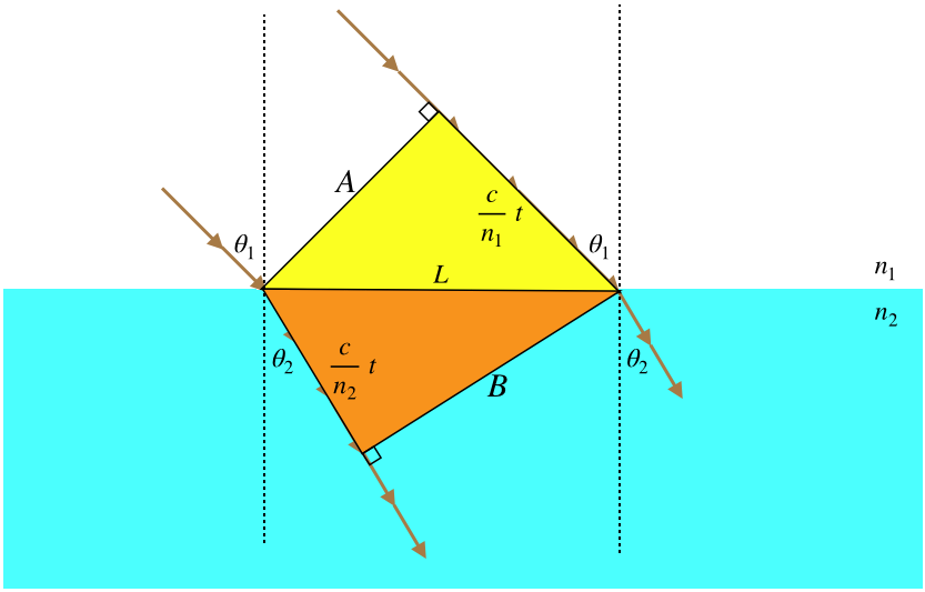
We are looking at what happens to a wavefront when it passes from position \(A\) to position \(B\). The left side of the wave front is traveling within medium #2, during the same time period that the right side is traveling through medium #1. The rays are by definition perpendicular to the wavefronts, and we have defined the angles the rays make with the perpendicular in each medium as \(\theta_1\) and \(\theta_2\). Before we do any of the math at all, we immediately note:
Light passing from a faster medium into a slower medium bends toward the perpendicular, and light passing from a slower medium to a faster medium bends away from the perpendicular.
While the second of these conclusions is not expressed in our figure, it's not hard to see that it must be true, if we just imagine the wavefronts in the figure moving up to the left from medium #2 to medium #1.
Now for the math. We have two right triangles (yellow and orange) with a common hypotenuse of length we have called \(L\). The distance between wavefronts in the upper medium is the speed of the wave there (\(\frac{c}{n_1}\)) multiplied by the time spent propagating, while the distance measured within the lower medium is calculated the same way, with a different speed (\(\frac{c}{n_2}\)). The angle \(\theta_1\) (shown on the right side of the diagram) is clearly the complement of the acute angle on the right-hand-side of the yellow triangle, which makes it equal to the acute angle on the left-hand-side of the yellow triangle. We therefore have:
\[\sin\theta_1=\dfrac{\left(\frac{c}{n_1}\right)t}{L}\]
Similarly we find for \(\theta_2\):
\[\sin\theta_2=\dfrac{\left(\frac{c}{n_2}\right)t}{L}\]
Dividing these two equations results in \(c\) and \(L\) dropping out, leaving:
\[n_1\sin\theta_1 = n_2\sin\theta_2\]
This relationship between the rays of a light wave which changes media is called the law of refraction, or Snell's law. While this works in either direction of light propagation, for reasons that will be clear next, it is generally accepted that the "1" subscript applies to the medium where the light is coming from, and the "2" subscript the medium that the light is going into.
Total Internal Reflection
It was noted above that light which passes from a slower medium to a faster one bends away from the perpendicular. What happens then if the incoming angle is made larger and larger (obviously it can't be more than \(90^o\))? For example, suppose we have \(n_1=2.0\), \(\theta_1=45^o\), and \(n_2=1.0\). Plugging these values into Snell's law gives:
\[\sin\theta_2 = \frac{n_1}{n_2}\sin\theta_1 = 2.0\cdot \sin 45^o = 1.4 \]
The sine function can never exceed 1, so there is no solution to this. This means that the light incident at this angle cannot be transmitted into the new medium. Every time light strikes a new medium some can be transmitted, and some reflected, so this result tells us that all of it must be reflected back into the medium in which it started. This phenomenon is called total internal reflection. The angle at which all of this first blows up is the one where the outgoing angle equals \(90^o\) (the outgoing light refracts parallel to the surface between the two media). This angle is called the critical angle, and is computed by choosing the outgoing angle to be \(90^o\):
\[n_1\sin\theta_c = n_2 \sin 90^o \;\;\;\Rightarrow\;\;\; \theta_c =\sin^{-1}\left(\dfrac{n_2}{n_1}\right)\]
Figure 3.6.9 – Partial and Total Internal Reflections By Incident Angle
Note that there is at least partial reflection (obeying the law of reflection) every time the light hits the surface, but all of the light along that ray is only reflected when the ray's angle exceeds the critical angle.
Alert
Note that when light is coming from one medium to another, unless that light is a plane wave, it will be moving in many directions at once. Only the portions of the light wave with rays that equal or exceed the critical angle are not transmitted into the new medium. So the word "total" in "total internal reflection" to express the fraction of light at a specific angle that is reflected back, not necessarily the fraction of all the light that is reflected back.
Example \(\PageIndex{1}\)
The diagram to the right shows the path of a ray of monochromatic light as it hits the surfaces between four different media (only the primary ray is considered – partial reflections are ignored). Order the four media according to the magnitudes of their indices of refraction.

- Solution
-
We know from Snell’s Law that when light passes from a higher index to a lower one, it bends away from the perpendicular, so we immediately have \(n_1>n_2>n_3\). For the ray to reflect back from the fourth medium, it has to be a total internal reflection (we are only considering primary rays, so this is not a partial reflection), which can only occur when light is going from a higher index of refraction to a lower one, so \(n_3>n_4\).
Dispersion
What determines the index of refraction for a medium is a very complicated problem in E&M, but there is one easily-observable fact: The amount that a ray bends as it enters a new medium is dependent upon the light’s frequency. Specifically, the higher the frequency of the light, the more it bends – it essentially experiences a higher index of refraction when its frequency is higher. This phenomenon is most evident when white light is shone through a refracting object. The most iconic example of this is white light through a prism.
Figure 3.6.10 – Dispersion Through a Prism

The emergence of the fully-separated spectrum of colors from a prism is reminiscent of a rainbow, and in fact rainbows are also a result of dispersion. Unlike the prism depicted above, however, internal reflection is an integral part of the rainbow effect (and in fact prisms can also feature internal reflection).
A droplet of water suspended in the atmosphere is a refracting sphere. White light that enters near the top of the droplet gets dispersed inside the droplet, reflects, and then gets dispersed as it exits the droplet, sending rays of different-colored light in different directions. The diagram below shows this effect for rays of red and blue light for two droplets.
Figure 3.6.11 – Rainbows
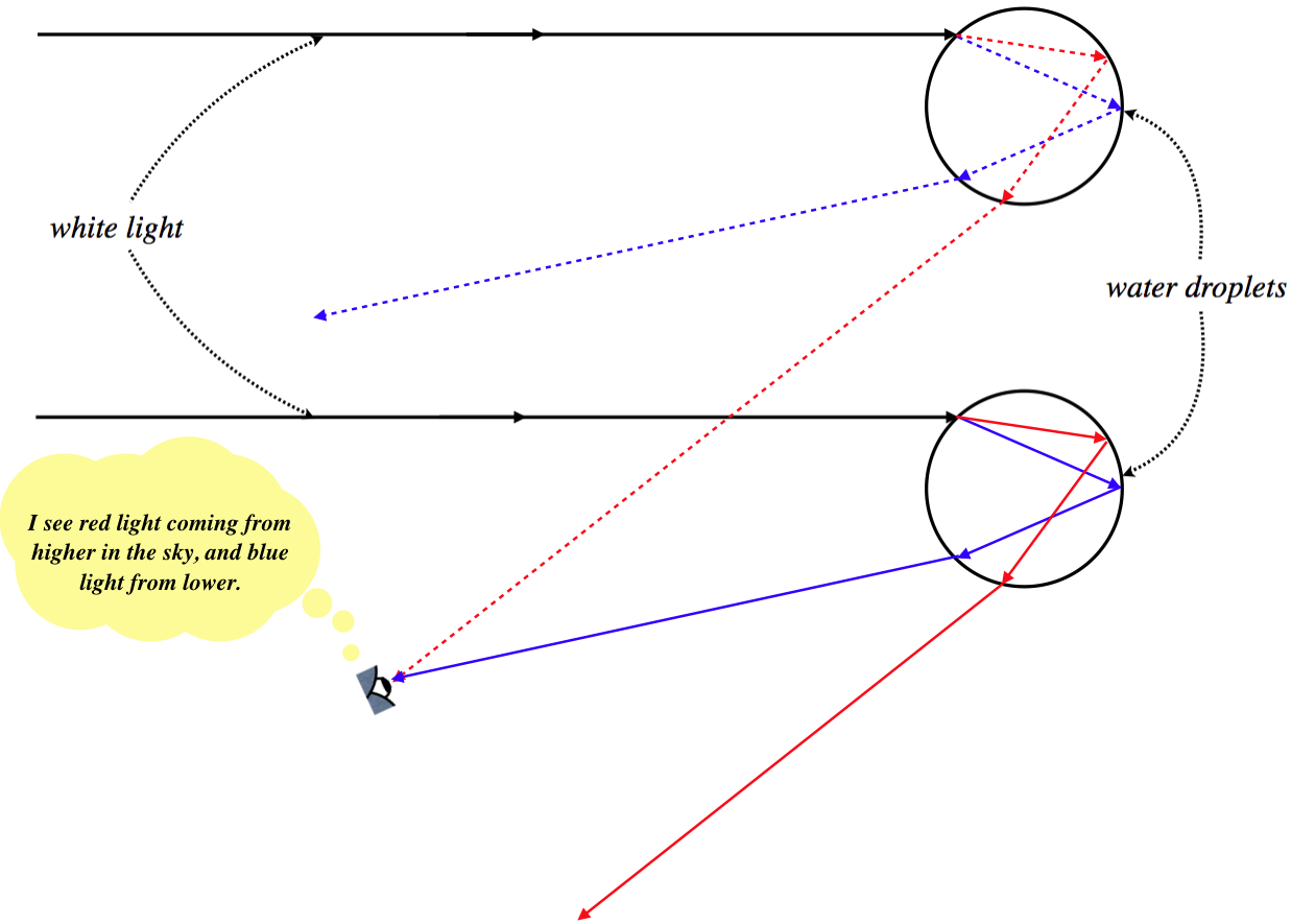
A few things to note here:
- Notice that the sun always needs to be behind the observer in order to witness a rainbow. That’s why it seems to move as you move, and why reaching the “end of the rainbow” is impossible (unless you can catch a leprechaun).
- The reason it is shaped like a bow is that the sun is nearly a point source, so the geometry is symmetric around the line joining the sun and the observer. If you create a “human-made rainbow” with a light and some mist, you can get close to an entire circle (minus whatever light your body blocks out).
- The secondary rainbow above the primary one comes from the light that enters the bottom of the droplets, and has two internal reflections. This reversed direction of the light bouncing around inside the droplets results in the colors being reversed (the violet is at the top and the red at the bottom).