
5.2: Activities
- Page ID
- 23045

Equipment
- component board
- 15V DC power supply
- variable capacitor
- Pasco box and laptop
- oscilloscope
- wires
The General Idea
The experiment portion of this lab is straightforward. You are given a variable capacitor, and are asked to compute its capacitance based on what you know about its geometric structure. Then you are tasked with checking this computation by connecting it into an RC circuit with a known resistance, and viewing the time dependence of its voltage on an oscilloscope. There is, however, an exploratory preamble to the experiment, in which you will write up only a brief summary of your findings in the lab report. The first part of this preamble consists of spending a little time exploring the properties of an LED light bulb (in the context of an RC circuit, of course). The second involves tinkering with an oscilloscope until you become familiar with its most basic functions.
Some Things to Think About
Part 1: Exploration – LED
Just about everyone has heard of LED lights. Far fewer know what "LED" stands for (light emitting diode). Fewer still know what the properties of such a component are in a circuit. Your task here is to find out, and to use it in an RC circuit to observe that circuit's time-dependent behavior. Like any other light, its brightness indicates the amount of current running through it. Besides the LED light on the component board, you will need the \(3300\mu F\) capacitor next to it (see the Background Material for a picture), and of course the \(15V\) DC power supply. Feel free to connect the LED with one or more of the other two components in any way you see fit, subject only to the following restriction:
Like capacitors we have used in past labs, this one has a specific polarity. When connected to the power supply, the positive (red) lead of the capacitor must be connected to the positive lead of the battery.
Make a mention of whatever you discover about any special properties of the LED in your lab report. You may want to ask your TA if what you have discovered "is really a thing."
Part 2: Exploration – Oscilloscope
- reference – You may want to refer back to the Background Material during this activity, to help you keep track of how the oscilloscope knobs affect what you see.
- practice – Throughout this exploration, you should not be satisfied with seeing how knobs affect the pattern on the screen ("Oh, this knob makes the wave taller!") – you should become comfortable with reading the numerical values that the device measures, and how to read the new numbers shown when the knob settings are changed.
- settings – to check and then never change once they are correct are:
- In the TRIGGER section set the slide switches to...
- MODE: P-P AUTO
- SOURCE: CH 1 and LINE
- All the smaller dials labeled "CAL" within the three largest dials (for voltage and time) should be turned fully clockwise.
- In the HORIZONTAL section, set the slide switch to X1.
- In the CH 1 part of the VERTICAL section set the slide switches to...
- upper slide switch: CH 1
- lower slide switch: DC
- The CH 2 part of the VERTICAL section can be ignored (the probe wires should be connected into the CH 1 connector).
- In the TRIGGER section set the slide switches to...
- calibration – Turn on the oscilloscope, and once you see its “trace” (the blue-green luminescent line), set the voltage in the CH1 part of the VERTICAL section to 5 volts per division (we use 1x, so ignore the 10x), and set the time scale in the HORIZONTAL section around the middle of its settings. Then place the oscilloscope leads across your 15V “battery,” black to black and red to red. While watching carefully, temporarily move the bottom slide switch in the CH1 part of the VERTICAL section to GND (essentially making the input zero) then back to DC. This should tell you something about the positioning of the beam.
- play time! – Open the laptop computer file “RC_Circuits,” and click the ON button in the Signal Generator window. Place the scope leads across the Output 1 signal generator outputs of the Pasco box, black to
 , and red to
  . Play around with the onscreen Waveform, Frequency and Amplitude settings (in the interest of efficiency, 2 or 3 waveforms should be plenty), and scope Volts/Div, Sec/Div, and Position controls. Note: The defaults obscured under "Offset and Limits" in the laptop software are chosen to protect our equipment – don’t change them! As noted earlier, be sure that you can read numbers off the screen properly, and that they confirm what signal you know is being sent from the Pasco box. Consult your TA to confirm that you are getting things right, or if you have any problems with the equipment.
Part 3: Experiment – Confirming Capacitance
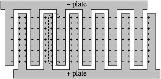
- variable capacitor – The device in the plastic box with a know that turns some interleaving metal plates is a variable capacitor. Turning the dial can move the plates into parallel positions, or remove them from those positions, thereby changing it total capacitance. The plates that rotate are charged with one sign, and the stationary plates are charged with the opposite sign, giving something (when the plates are meshed) that looks like the diagram below, up-close. The important thing to note is that each gap represents an individual capacitor, and since all of the positive plates are at the same potential as each other, as are all the negative plates, these individual capacitors are connected in parallel.
- safety – For your own safety, and to protect this quite delicate instrument (did we mention that the plates are separated by a quarter of a millimeter?!), please:
- Never touch the plates!
- Be careful not to drop the device or try to "repair" it. If you suspect that it is shorted because it doesn't seem to be functioning properly, and/or you can feel/hear the plates rubbing each other when you turn the dial, just let your TA know, and they will check it and get you a replacement if needed.
- Be sure to connect a conductor (short the capacitor) between tasks or when you are done with it, so that there is no lingering charge within it.
- specifications – The semicircular plates of this capacitor have a diameter of about \(3.5cm\) and the spacings (when interleaved) are about \(0.25mm\).
- compute capacitance – The main thrust of the experiment is to compare the capacitance found using the oscilloscope readings for an RC circuit to the computed capacitance. The information above should be sufficient to compute an approximate capacitance from its geometrical structure.
- RC circuit – The RC circuit you will be building consists of the variable capacitor, the \(100k\Omega\) resistor (see the Background Material for a reminder of which component this is), and the Pasco signal generator. (Question to ponder: Why can't we just use the DC power supply?) Here are a few suggestions for the settings of the signal generator:
- waveform: square
- frequency: \(1000 Hz\)
- amplitude: \(2.5 V\) (since amplitude is half the total maximum fluctuation, this is a \(5V\) variation in the voltage)
- oscilloscope connection – Remember that the oscilloscope is a voltmeter, which means we can use it to indirectly measure the time dependence of either the current (if we measure the voltage across the resistor) or the charge (measuring the voltage across the capacitance). Important additional note: The oscilloscope won’t read voltage properly unless its black lead is effectively attached to the signal generator’s jack, i.e., either to that jack or to a wire going there. So pay attention to the order in which you wire the resistor and capacitor in series; if you want to “look” at the capacitor voltage, make sure it has one lead going to the signal generator’s jack, and if you want to “look” at the resistor, make sure it has one lead going there. Of course, in this series circuit, they can’t both go there.
- observe the effect of changing capacitance – When everything is set up and your oscilloscope is reading values properly, turn the dial of your variable capacitor to see what effect it has on the output. Explain this effect in your lab report.
- oscilloscope readings and math – You will be computing the maximum capacitance of this variable capacitor (the same thing you computed earlier, when all the plates are interleaved). To compute the capacitance from the data you take, you will need to properly read the numbers from the oscilloscope, and apply them to the mathematical relation for either \(Q\left(t\right)\) or \(I\left(t\right)\) for a charging or discharging RC circuit. You know the resistance of the circuit, and the time dependence, and that is all you need.
- sources of error – Be sure to make a brief approximate accounting of where errors can creep into this experiment. Mentioning error sources is useful, making reasoned approximations of percentage error, when possible, is better.
- things to include in lab report – Besides the items explicitly mentioned above and details of the computations you make, it's always a good idea to have some record of your raw data in the report, so you should include a photo of the oscilloscope reading + dial settings.
Lab Report
Craft a lab report for these activities and analysis, making sure to include every contributing group member's name on the front page. You are strongly encouraged to refer back to the Read Me as you do this, to make sure that you are not leaving out anything important. You should also feel free to get feedback from your lab TA whenever you find that your group is at an impasse.
Every member of the group must upload a separate digital copy of the report to their lab assignment in Canvas prior to leaving the lab classroom. These reports are not to be written outside the lab setting.