
2.5: Dielectrics
- Page ID
- 17358

Polarization
Up to now, we have placed all substances into one of two categories – insulators and conductors – distinguished by whether they hold charges utterly fixed or allow them completely free movement. Well, it probably isn’t surprising that in reality substances generally fall between these two extremes. For now we will focus on the insulator side of the spectrum. Imagine a substance that doesn’t allow charges to go wherever they please, but does allow for the atoms or molecules binding these charges to morph their shapes. Such substances are called dielectrics, and they actually provide an effect similar to what is seen in conductors, though it is not extreme enough to completely cancel the field.
Start with a slab of neutrally-charged dielectric located between two neutrally-charged conductor plates. If the plates are then charged, the electric field produced between the two plates pull the charges in the dielectric in opposite directions. Within the dielectric, the positive and negative charges just pair-off differently, leaving a continued neutral charge. But on the surfaces, the separated charges don't pair-off with opposites, leaving a net charge on the two surfaces of the dielectric called polarization charge.
Figure 2.5.1 – Creation of Polarization Charge on a Dielectric
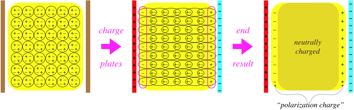
We saw this same thing happen in a conductor, but because the charges were totally free to move, they continued polarizing until the net field vanished within the conductor. In the case of dielectrics, the charges stop shifting long before the field of the polarization charge can cancel the field of the free charge, which means that there is still a net field remaining within the dielectric at the end.
For the parallel-plate geometry in the figure above, the net field is easy to compute from the free and polarization charges, as they are both planes. We can similarly solve for the net field in the case of a dielectric inside a capacitor of concentric conducting cylinders. But things get far too complicated when the surface of the dielectric is not orthogonal to the external field, so we will only consider these simpler geometries. Furthermore, we will assume that the entire dielectric is the same material – the amount that the charges are able to separate depends upon the molecules, so they have to be the same throughout the sample.
With these restrictions in place, we can conclude that the field caused by the polarization charge (called the polarization field) is in the direction opposite to the applied field, and since the applied field is always stronger, we can write:
\[\left|\overrightarrow E_{total}\right| = \left|\overrightarrow E_{applied}\right| - \left|\overrightarrow E_{polarization}\right| \]
It's clear that increasing the strength of the applied field pulls harder on the charges in the dielectric, and should increase the polarization charge. We make the further assumption (demonstrated experimentally, as long as the applied field is not too strong) that if we double the field strength, the polarization field also doubles. That is, the polarization field is proportional to the applied field. Combining this with the equation above means that the applied field is proportional to and in the same direction as the total field (with the applied field stronger), and we will write the constant of proportionality, called the dielectric constant as a lower-case Greek letter kappa:
\[\kappa \equiv \dfrac{\left|\overrightarrow E_{applied}\right|}{\left|\overrightarrow E_{total}\right|} \]
Note that this constant is dimensionless, is greater than or equal to 1. It is equal to 1 for a vacuum (where there are no charges to polarize), or a perfect insulator (which allows no charge movement at all).
Effects on Capacitors
The most common application of dielectrics is in capacitors, as one would guess from the figure. How is the capacitance affected by the presence of this substance? Given the same charges on the plates, the polarization charge reduces the electric field between the plates compared to the vacuum case, so the voltage difference is decreased. With a smaller voltage for the same charge on the plates, the capacitance is increased. Specifically, it is increased by a factor of exactly the dielectric constant:
\[C_{dielectric} = \dfrac{Q_{on\;plates}}{\Delta V_{total}} = \dfrac{Q_{on\;plates}}{\int\limits_{plate\;A}^{plate\;B}\overrightarrow E_{total}\cdot \overrightarrow{dl}} = \dfrac{Q_{on\;plates}}{\int\limits_{plate\;A}^{plate\;B}\frac{1}{\kappa}\overrightarrow E_{applied}\cdot \overrightarrow{dl}} = \kappa\dfrac{Q_{on\;plates}}{\Delta V_{vacuum}}=\kappa C_{vacuum}\]
We noted several sections ago that the primary purpose of a capacitor is to store electrical potential energy. Let's now consider what happens to the potential energy when a dielectric is added into or taken out of a capacitor. Adding a dielectric increases the capacitance, and taking it away reduces it. From here, we can follow the calculations performed in Example 2.4.1. It was noted there that the change in energy depends upon what is held constant as the capacitance is changed – the charge on the plates, or the potential difference, and that must be taken into account here as well. The only difference here is that the capacitance changes as a result of the dielectric constant changing, rather than a change in the separation of the plates.
The overall result is the same – with the capacitance increasing when the dielectric is inserted, the potential energy goes up if the potential difference is held fixed, and it goes down if the plates are forces to keep the same charge. But in the example cited, the energy changes were accounted-for by considering the work done in separating the plates. Here the plate separation doesn't change, so if there is no work done, how can we account for where the energy comes from or goes to?
Well, in fact there is work done in the removal or insertion of the dielectric. We can see this by looking at what the system must look like when the dielectric is partially-inserted. The polarization charge on the surface of the dielectric that is between the plates will be attracted to the free charge on the part of the plates that are still separated by vacuum:
Figure 2.5.2 – Force on a Partially-Inserted Dielectric
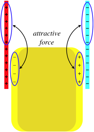
In order to pull the dielectric out of the capacitor requires that work be added to the system (equivalent to increasing the plate separation in Example 2.4.1), while allowing the dielectric to be pulled into the capacitor removes energy from the system in the form of work done on the dielectric. This analysis can be performed "in reverse" to determine the force exerted on a partially-inserted dielectric by the capacitor. In Physics 9A, we learned that the force due to a potential energy field is equal to the negative of the gradient of the potential energy (see Physics 9A Libretext, Section 3.6):
\[\overrightarrow F = -\overrightarrow\nabla U\]
The change only occurs parallel to the plates, which we will call the \(y\)-direction, so this simplifies to just one component:
\[ F_y = -\dfrac{dU}{dy} \]
When the dielectric moves into the plates an additional tiny distance \(dy\), the potential energy of the system changes. How much it changes depends once again upon whether the charge on the plates or the potential difference remains constant during the process (the dependence of work done on which quantity is held constant was also a feature of Example 2.4.1). So all one needs to do is write down the potential energy for the capacitor at whatever position the dielectric is in, recalculate it for the dielectric inserted an additional distance \(dy\), take the difference to obtain \(dU\), then divide by \(dy\). An important part of this process is noting that the capacitor with a partial dielectric inserted is equivalent to two separate capacitors, one with a vacuum between the plates, and one with dielectric between them. The total energy of the system is the sum of the energy in these two capacitors, and one needs to keep in mind that as each plate is an equipotential, the potential difference between the two plates for the two separate capacitors is the same.
Permittivity
One way that the dielectric constant is accounted-for is within another constant that we are already familiar with. To see this, consider how the capacitance of a parallel plate capacitor containing a vacuum changes when a dielectric is inserted:
\[C_{vacuum} = \dfrac{A\epsilon_o}{d} \;\;\;\Rightarrow\;\;\; C_{dielectric} = \kappa\dfrac{A\epsilon_o}{d}= \dfrac{A\epsilon}{d}\;,\;\;\; where:\;\;\epsilon\equiv\kappa\epsilon_o\]
At last it’s clear why the ‘o’ subscript was used up to now: The ‘o’ refers to the vacuum, which is why it is called the permittivity of free space. The quantity \(\epsilon\) (with no subscript) is simply called the permittivity of the dielectric. The advantage of making this definition is that it saves us the trouble of re-deriving all the results where we used \(\epsilon_o\) previously for cases where a dielectric medium is involved. It turns out that we can simply blindly replace the free-space constant with that for the dielectric, and all the same results apply. There is, however, one important detail to keep in mind here, however.
We introduced the dielectric constant and then the permittivity as a means of ignoring the polarization charge. That is, the capacitance with a dielectric still satisfies \(Q=CV\), where \(Q\) is the charge on the plates, not the combination of the charge on the plates with the polarization charge. Wherever we use the permittivity, the requirement that we only account for the free charge (the charge present that excludes the polarization charge) must be observed. An important example of following this requirement follows.
Gauss's Law in Media
Consider the case of employing Gauss's law to determine the electric field near the surface of a conducting plane, as we did in Figure 1.7.2, but this time with a dielectric medium present outside the conducting surface.
Figure 2.5.3 – Gaussian Surface for a Conducting Surface Near a Dielectric
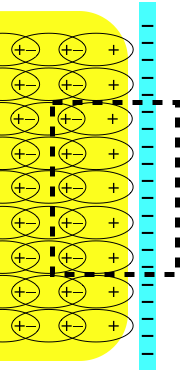
This gaussian surface encloses both the free charge on the conducting surface and the polarization charge on the surface of the dielectric. The net flux out of the gaussian surface (all of it gong through the left side of the surface shown) is lower than it would be without the dielectric, because the polarization charge cancels some of the free charge. The difference in flux comes entirely from the difference in the electric field, which we already know how to express:
\[\Phi_{with\;dielectric} = E_{total}A = \frac{1}{\kappa} E_{applied}A = \frac{1}{\kappa} \Phi_{without\;dielectric} = \dfrac{\epsilon_o}{\epsilon}\Phi_{without\;dielectric}\]
According to Gauss's law, the flux without the dielectric is just \(\frac{Q_{plate}}{\epsilon_o}\), so we can express Gauss's law in terms of the free charge enclosed rather than the total charge enclosed using the dielectric permittivity:
\[ \oint \overrightarrow E\cdot d\overrightarrow A = \dfrac{Q_{free}}{\epsilon} \]
In local form, this becomes:
\[ \overrightarrow\nabla\cdot \overrightarrow E=\dfrac{\rho_{free}}{\epsilon} \]
All of the other appearances of the permittivity that we have seen similarly carry-over, most notably:
\[u=\frac{1}{2}\epsilon E^2\]
Example \(\PageIndex{1}\)
A point charge is held fixed in a medium with a dielectric constant equal to 2 near a large conducting plane. If the dielectric is now removed, describe how the following quantities change:
- the force on the point charge by the conductor
- the charge induced on the surface of the conductor
- Solution
-
a. The electric field is the same in both cases, with the exception of the value of the permittivity, which is twice as great when the dielectric is in place than when it is not. This weakens the electric field of the point charge by a factor of 2. The induced charge on the conducting surface therefore responds by producing an equivalent field as if originating from an image charge. This weaker induced field results in a force on the point charge that is half as strong as when the dielectric is absent.
b. The charge induced on the surface of the conductor equals the negative of the point charge whether the dielectric is present or not. We can prove this a couple of ways. The simplest is to note that Newton's third law requires that if the force on the point charge is half as much with the dielectric, then the force on the conductor is also half as great. But the field of the point charge is half as strong, so the charge on which this field is acting must not be changed.
A second way to show this is to note that the electric field at the surface of a conductor in terms of the charge density is:
\[E = \dfrac{\sigma_{free}}{\epsilon}\nonumber\]
We already know that the field is half as strong with the dielectric in place, and since \(\epsilon=2\epsilon_o\), the charge density must be the same in both cases.