
3.4: Kirchhoff's Rules
- Page ID
- 21519

Some Problems Cannot Be Solved with \(R_{eq}\) and \(C_{eq}\)
Despite our ability to reduce circuits using equivalent resistances and capacitances, we can’t analyze every circuit imaginable using those shortcuts. For example:
Figure 3.4.1 – Circuits Not Solvable with Equivalent Resistance and Capacitance
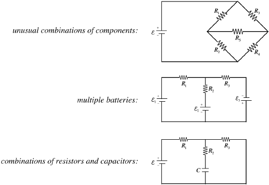
It is possible to reduce fragments of networks with equivalent resistance/capacitance to simplify our work, but we have to be certain that the elements we are combining truly follow both of the conditions for the type of equivalence we are using. For example, in the third figure above, one might be inclined to proclaim that \(R_2\) and \(R_3\) are in parallel. After all, it's clear that the total current that comes into the junction joining them equals the sum of the currents through each. Well, that's one criterion, but what about the other – that the voltage drops across each is equal? This fails because the capacitor has a voltage drop across it.
Getting Back to Basics
So how do we solve such problems? We do this by using the same principles that led to the equivalence formulas, which comes down to two simple rules (called Kirchhoff's rules) that are based on charge conservation and energy conservation.
junction rule – Charge remains conserved, so since there is no charge build-up or loss at any junction in a network, the rate at which charge enters a junction equals the rate at which it exits the junction. Put another way, the current into a junction equals the current out of that junction.
loop rule – Energy remains conserved, which means that when a charge travels around any loop in a network to return to where it started, its potential energy \(qV\) should return to the value it had when it was previously at that position. [This of course also presupposes that the emf source is supplying energy to the circuit at the same rate that the circuits resistance is converting energy to thermal, and that the kinetic energy of the charge doesn't change.] Put another way, the sum of the voltage drops around any closed loop is zero.
Applying these two rules to simple series and parallel circuits results in the same equivalence rules that we have already, but now these can be used to solve the more complicated problems mentioned above.
Problem Solving
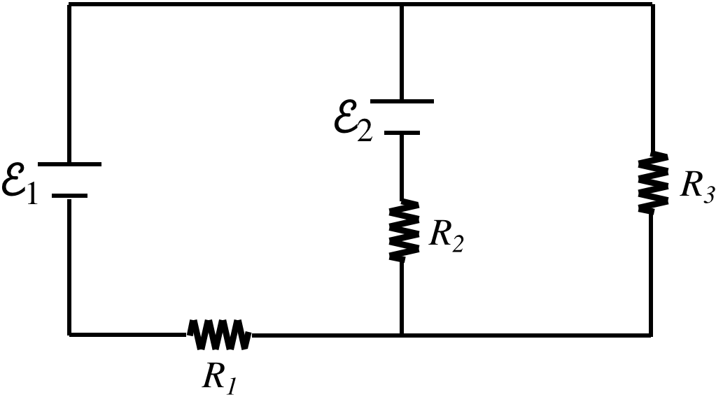
Let's consider a problem involving two batteries and multiple loops:
Figure 3.4.2a – Using Kirchhoff's Rules on a Network
Our goal is to find the current that runs through each of the resistors. There are some very standard steps to follow, and the most important thing to remember is that there exist many choices for these steps, and none of these choices is wrong. Don't get slowed down by trying to decide on the "correct" choice to make – every choice will get to the same answer! Without further ado, the steps:
- label the currents
We are solving for the currents, so we need some variables to solve for. But a variable alone is not enough, we also need to label a direction for that current.
Figure 3.4.2b – Using Kirchhoff's Rules on a Network
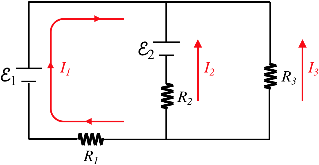
Wait, these currents can't be right – they are all converging on the same junction! No, this labeling is perfectly fine, because in the end we will solve a system of equations, and one or two of these currents will end up being a negative number, indicating that the actual direction of the current is opposite to what we have labeled. We make these labels to solve the problem, and there is no need to be concerned with guessing the actual direction of current flow.
- apply the junction rule
Identify all of the junctions in the diagram (in this case, there are two). We will not require all of the junctions, as we will see here. Choosing the upper junction in this case, and setting the incoming current equal to the outgoing current gives:
\[current\;in = I_1+I_2+I_3 = 0 = current\;out\]
Note that if we choose the other junction, the current in is zero and the current out is the sum of the three individual currents, giving us the same equation. The number of useful junction equations will be one fewer than the total number of junctions. As stated earlier, we can frequently reduce the need for junction equations by using equivalent resistance wherever possible.
- apply the loop rule
Identify all of the loops in the diagram (in this case, there are three – left, right, and outer). As in the case of junctions, we will not require all of the loops (i.e. after we have enough of them, additional loops provide redundant information). The simple way to know if enough loops have been included is to count the number of unknowns and the number of equations. In this case, we have three unknowns (the three currents), and we already have one equation (the junction equation), so we need to use two different loops to attain enough equations to solve for the currents.
This step, while easily stated, comes with many sub-steps. For each loop that is be used, follow the following procedure:
- choose a loop direction – clockwise or counterclockwise
- choose a starting point – any point on the loop will do
- follow the loop in the chosen direction and construct a sum of the voltage drops in that direction
- When crossing over a battery (or a capacitor):
- Add a positive value equal to the battery's emf if the loop journey crosses from the negative terminal to the positive terminal, because this is an increase in potential.
- Add a value equal to the negative of the battery's emf if the loop journey crosses from the positive terminal to the negative terminal, because this is a decrease in potential.
- When crossing over a resistor:
- Add a value equal to \(-IR\) (where \(I\) is the current labeled and \(R\) is the resistor encountered) if the direction of the loop journey matches the direction of the labeled current. This is because current always flows from higher to lower potential.
- Add a value equal to \(+IR\) if the direction of the loop journey is opposite to the direction of the labeled current.
- set the sum of voltage drops equal to zero
For the example at hand, this all looks like this (all three loops are provided here, but only two of the equations are needed):
\[\begin{array}{l} \text{left loop, clockwise, start in lower-left corner:} && +\mathcal E_1 - \mathcal E_2 + I_2R_2 - I_1R_1 = 0 \\ \text{right loop, clockwise, start in lower-left corner:} && -I_2R_2+\mathcal E_2 + I_3R_3 = 0 \\ \text{outer loop, clockwise, start in lower-left corner:} && +\mathcal E_1 + I_3R_3 - I_1R_1 = 0 \end{array}\]
- do the algebra – Solve the simultaneous equations using whatever method you prefer.
Of course, there are many variations on problems – the battery emfs and resistances are not always what is given – but the same principles apply.
Example \(\PageIndex{1}\)
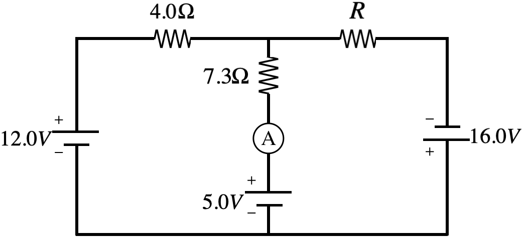
Find the resistance \(R\) in the network diagrammed below for which the ammeter will measure zero current.
- Solution
-
Noting that there is no current in the central segment and summing the voltage drops clockwise around the left loop (starting at the lower left corner) gives us the current in the outer loop:
\[+12.0V - I\left(4.0\Omega\right) - \left(0A\right)\left(7.3\Omega\right) - 5.0V = 0 \;\;\;\Rightarrow\;\;\; I = \dfrac{7}{4}A\nonumber\]
Now use that current to sum the voltage drops around the outer loop to find \(R\):
\[+12.0V - I\left(4.0\Omega\right) - \left(\dfrac{7}{4}A\right)R + 16.0V = 0 \;\;\;\Rightarrow\;\;\; R = 12.0\Omega\nonumber\]