
10.5: AC Generator
- Page ID
- 5477

This and the following sections will be devoted to generators and motors. I shall not be concerned with – and indeed am not knowledgeable about – the engineering design or practical details of real generators or motors, but only with the scientific principles involved. The "generators" and "motors" of this chapter will be highly idealized abstract concepts bearing little obvious resemblance to the real things. Need an engineering student, then, pay any attention to this? Well, of course, all real generators and motors obey and are designed around these very scientific principles, and they wouldn't work unless their designers and builders had a very clear knowledge and understanding of the basic principles.
The rod sliding on rails in a magnetic field described in Section 10.2 in fact was a D.C. (direct current) generator. I now describe an A.C. (alternating current) generator.
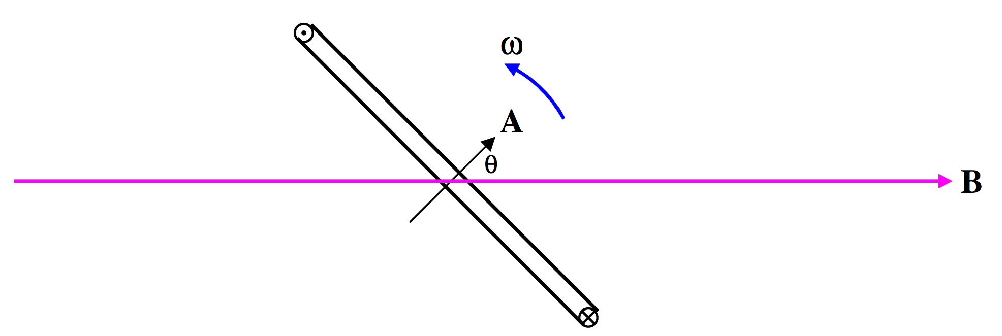
\(\text{FIGURE X.5}\)
In Figure X.5 we have a magnetic field \(\textbf{B}\), and inside the field we have a coil of area \(\textbf{A}\) (yes – area is a vector) and N turns. The coil is being physically turned counterclockwise by some outside agency at an angular speed \(\omega\) radians per second. I am not concerned with who, what or how it is being physically turned. For all I know, it might be turned by a little man turning a hand crank, or by a steam turbine driven by a coal- or oil-burning plant, or by a nuclear reactor, or it might be driven by a water turbine from a hydroelectric generating plant, or it might be turned by having something rubbing against the rim of your bicycle wheel. All I am interested in is that it is being mechanically turned at an angular speed \(\omega\). As the coil turns, the flux through it changes, and a current flows through the coil in a direction such that the magnetic moment generated for the coil is in the direction indicated for the area \(\textbf{A}\) in Figure X.5, and also indicated by the symbols \(\bigodot \text{ and }\bigotimes\). This will result in an opposition to rotation of the coil; whoever or whatever is causing the coil to rotate will experience some opposition to his efforts and will have to do work. You can also deduce the direction of the induced current by considering the direction of the Lorentz force on the electrons in the wire of the coil.
At the instant illustrated in Figure X.5, the flux through the coil is \(AB \cos θ\), or \(AB \cos \omega t\), if we assume that \(θ = 0\text{ at }t = 0\). The rate of change of flux through the coil at this instant is the time derivative of this, or \(-AB \omega \sin \omega t\). The magnitude of the induced EMF is therefore
\[\label{10.5.1}V=NAB\omega \sin \omega t = \hat{V}\sin \omega t,\]
where \(\hat{V}\) (" \(V\)-peak") is the peak or maximum EMF, given by
\[\label{10.5.2}\hat{V}=NAB\omega .\]
Are you surprised that the peak EMF is proportional to \(N\) ? To \(A\) ? To \(B\) ? To \(\omega\) ? Verify that \(NAB \omega\) has the correct dimensions for \(\hat{V}\).
The peak EMF occurs when the flux through the coil is changing most rapidly; this occurs when \(θ = 90^\circ\), at which time the coil is horizontal and the flux through it is zero.
The leads from the coil can be connected to an external circuit via a pair of slip rings through which they can deliver current to the circuit.
The actual physical design of a generator is beyond the scope of this chapter and indeed of my expertise, though all depend on the physical principles herein described. In the "design" (such as it is) that I have described, the coil in which the EMF is induced is the rotor while the magnet is the stator – but this need not always be the case, and indeed designs are perfectly possible in which the magnet is the rotor and the coil the stator. In my design, too, I have assumed that there is but one coil – but there might be several in different planes. For example, you might have three coils whose planes make angles of \(120^\circ\) with each other. Each then generates a sinusoidal voltage, but the phase of each differs by \(120^\circ\) from the phases of the other two. This enables the delivery of power to three circuits. In a common arrangement these three circuits are not independent, but each is connected to a common line. The EMF in this common line is then made up three sine waves differing in phase by \(120^\circ\):
\[\label{10.5.3}V=\hat{V}[\sin \omega t +\sin (\omega t + 120^\circ ) +\sin (\omega t +240^\circ )].\]
There are several ways in which you can see what this is like. For example, you could calculate this expression for numerous values of \(t\) and plot the function out as a graph. Or you could expand the expressions \(V = \sin (\omega t +120^\circ ) \) and \(V = \sin (\omega t + 240^\circ )\), and gather the various terms together to see what you get. (I recommend trying this.) Or you could simply add the three components in a phase diagram:
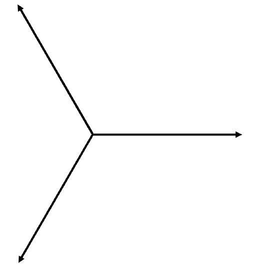
\(\text{FIGURE X.6}\)
It then becomes obvious that the sum is zero, and this line is the neutral line, the other three being live lines.