
10.7: Linear Motors and Generators
- Page ID
- 7891

Most (but not all!) real motors and generators are, of course, rotary. In this section I am going to describe highly idealized and imaginary linear motors and generators, only because the geometry is simpler than for rotary motors, and it is easier to explain certain principles. We'll move on the rotary motors afterwards.
In Figure X.7 I compare a motor and a generator. In both cases there is supposed to be an external magnetic field (from some external magnet) directed away from the reader. A metal rod is resting on a pair of conducting rails.
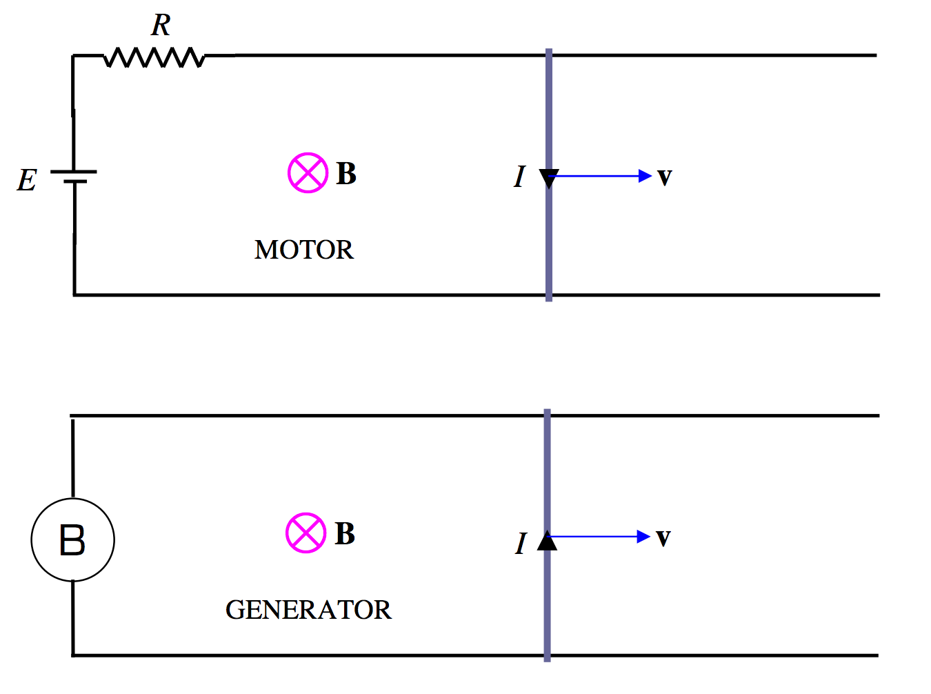
\(\text{FIGURE X.7}\)
In the motor, a battery is connected in the circuit, causing a current to flow clockwise around the circuit. The interaction between the current and the external magnetic field produces a force on the rod, moving it to the right.
In the generator, the rod is moved to the right by some externally applied force, and a current is induced counterclockwise. If the B inside the circle represents a light bulb, a current will flow through the bulb, and the bulb will light up.
Let us suppose that the rails are smooth and frictionless, and suppose that, in the motor, the rod isn't pulling any weight. That is to say, suppose that there is no mechanical load on the motor. How fast will the rod move? Since there is a force moving the rod to the right, will it continue to accelerate indefinitely to the right, with no limit to its eventual speed? No, this is not what happens. When the switch is first closed and the rod is stationary, a current will flow, given by \(E = IR\), where \(E\) is the EMF of the battery and \(R\) is the total resistance of the circuit. However, when the rod has reached a speed \(v\), the area of the circuit is increasing at a rate \(av\), and a back EMF (which opposes the EMF of the battery), of magnitude \(avB\) is induced, so the net EMF in the circuit is now \(E-avB\) and the current is correspondingly reduced according to
\[\label{10.7.6}E-avB=IR.\]
Eventually the rod reaches a limiting speed of \(E / (aB)\), at which point no further current is being taken from the battery, and the rod (sliding as it is on frictionless rails with no mechanical load) then obeys Newton's first law of motion – namely it will continue in its state of uniform motion, because no forces are no acting upon it.
Problem 1. Show that the speed increases with time according to
\[\label{10.7.7}v=\frac{E}{aB}\left ( 1- \text{exp}\left ( -\frac{(aB)^2t}{mR}\right ) \right ),\]
where \(m\) is the mass of the rod.
Problem 2. Show that the time for the rod to reach half of its maximum speed is
\[\label{10.7.8}t_{1/2}=\frac{mR\ln 2}{(aB)^2}.\]
Problem 3. Suppose that \(E = 120\text{ V},\, a = 1.6\text{ m} ,\, m = 1.92\text{ kg and }R = 4 \Omega\). If the rod reaches a speed of \(300\text{ m s}^{−1}\text{ in }300\text{ s}\), what is the strength of the magnetic field?
I'll give solutions to these problems at the end of this section. Until then – no peeking.
In a frictionless rotary motor, the situation would be similar. Initially the current would be \(E/R\), but, when the motor is rotating with angular speed \(\omega\), the average back EMF is \(2NAB \omega / \pi\) equations 10.5.2 and 10.6.5), and by the time this has reached the EMF of the battery, the frictionless, loadless coil carries on rotating at constant angular speed, taking no current from the battery.
Now let's go back to our linear motor consisting of a metal rod lying on two rails, but this time suppose that there is some mechanical resistance to the motion. This could be either because there is friction between the rod and the rails, or perhaps the rod is dragging a heavy weight behind it, or both. One way or another, let us suppose that the rod is subjected to a constant force \(F\) towards the left. As before, the relation between the current and the speed is given by Equation \ref{10.7.6}, but, when a steady state has been reached, the electromagnetic force \(aIB\) pulling the rod to the right is equal to the mechanical load \(F\) dragging the rod to the left. That is, \(E - av B = IR\text{ and }F = a I B\). If we eliminate \(I\) between these two equations, we obtain
\[\label{10.7.9}E-avB=\frac{FR}{aB},\]
or
\[\label{10.7.10}v=\frac{E}{aB}-\frac{R}{(a\,B)^2}F.\]
This equation, which relates the speed at which the motor runs to the mechanical load, is called the motor performance characteristic. In our particular motor, the performance characteristic shows that the speed at which the motor runs decreases steadily as the load is increased, and the motor runs to a grinding halt for a load equal to \(a B E / R\). (Verify that this has the dimensions of force.) The current is then \(E/R\). This current may be quite large. If you physically prevent a real motor from turning by applying a mechanical torque to it so large that the motor cannot move, a large current will flow through the coil – large enough to heat and possibly fuse the coil. You will hear a sharp crack and see a little puff of smoke.
If we multiply Equation \ref{10.7.6} by \(I\), we obtain
\[\label{10.7.11}EI=aIBv+I^2 R,\]
or
\[\label{10.7.12}EI=Fv+I^2R.\]
This shows that the power produced by the battery goes partly into doing external mechanical work, and the remainder is dissipated as heat in the resistance. Restrain the motor so that \(v = 0\), and all of that \(E I\) goes into \(I^2 R\).
If you were physically to move the rod to the right at a speed faster than the equilibrium speed, the back EMF becomes greater than the battery EMF, and current flows back into the battery. The device is then a generator rather than a motor.
The nature of the performance characteristic varies with the details of motor design. You may not want a motor whose speed decreases so drastically with load. You may have to decide in advance what sort of performance characteristic you want the motor to have, depending on what tasks you want it to perform, and then you have to design the motor accordingly. We shall mention some possibilities in the next section.
Now – the promised solutions to the problems.
Solution to Problem 1.
When the speed of the rod is \(v\), the net EMF in the circuit is \(E - a Bv\), so the current is \((E - a Bv) /R\), and so the force on the rod will be \(aB(E - a Bv) /R\) and the acceleration \(dv / dt\) will be \(aB(E - a Bv) /(mR)\). The equation of motion is therefore
\[\frac{dv}{E-aBv}=\frac{aB}{mR}dt.\label{10.7.13}\]
Integration, with \(v = 0\) when \(t = 0\), gives the required Equation \ref{10.7.7}.
Solution to Problem 2.
Just put \(v = \frac{E}{ 2a B}\) in Equation \ref{10.7.7} and solve for \(t\). Verify that the expression has the dimensions of time.
Solution to Problem 3.
Put the given numbers into Equation \ref{10.7.7} to get
\[\label{10.7.14}B=\frac{1}{4}(1-e^{-100B^2})\]
and solve this for \(B\). (Nice and easy. But if you are not experienced in solving equations such as this, the Newton-Raphson process is described in Chapter 1 of the Celestial Mechanics notes of this series. This equation would be good practice.) There are two possible answers, namely \(0.043996\) and 0.249505 teslas. I draw the speed:time graphs for the two solutions below:
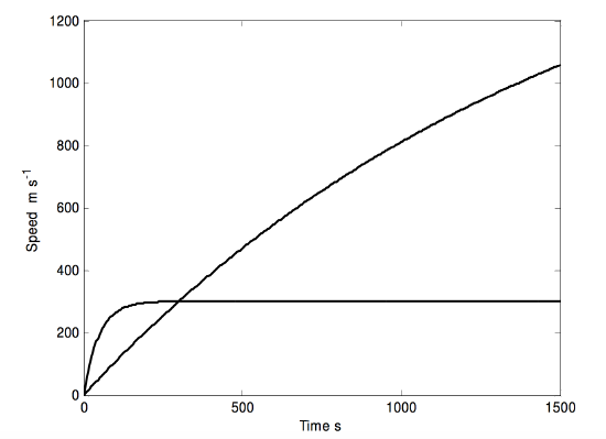
Numbers of interest for the two fields:
\[\nonumber \begin{align}&B\text{ (T)}\quad \quad &v_\infty (\text{m s}^{-1})\quad\quad\quad &\overline t\,\text{ s} \\ \nonumber \\ \nonumber&0.0440 \quad\quad &1704.7 \quad\quad\quad &1074.29 \\ \nonumber &0.2495 \quad\quad &300.6 \quad\quad\quad &33.40 \\ \end{align}\]