
B28: Thin Lenses - Ray Tracing
- Page ID
- 7775

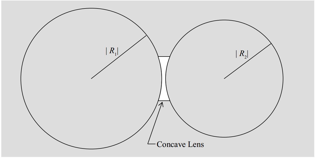
A lens is a piece of transparent material whose surfaces have been shaped so that, when the lens is in another transparent material (call it medium 0), light traveling in medium 0, upon passing through the lens, is redirected to create an image of the light source. Medium 0 is typically air, and lenses are typically made of glass or plastic. In this chapter we focus on a particular class of lenses, a class known as thin spherical lenses. Each surface of a thin spherical lens is a tiny fraction of a spherical surface. For instance, consider the two spheres:
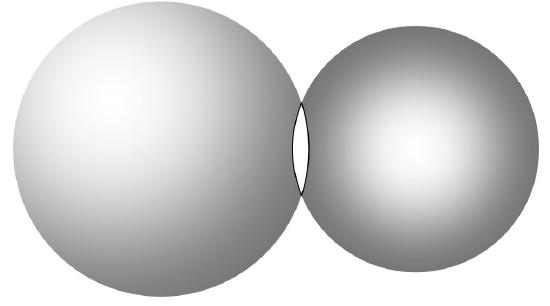
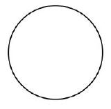
A piece of glass in the shape of the intersection of these two spherical volumes would be a thin spherical lens. The intersection of two spherical surfaces is a circle. That circle would be the rim of the lens. Viewed face on, the outline of a thin spherical lens is a circle.
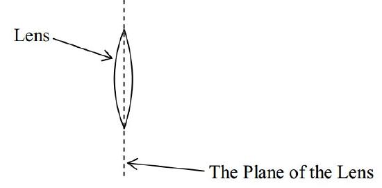
The plane in which that circle lies is called the plane of the lens. Viewing the lens edge-on, the plane of the lens looks like a line.
Each surface of a thin spherical lens has a radius of curvature. The radius of curvature of a surface of a thin spherical lens is the radius of the sphere of which that surface is a part. Designating one surface of the lens as the front surface of the lens and one surface as the back surface, in the following diagram:
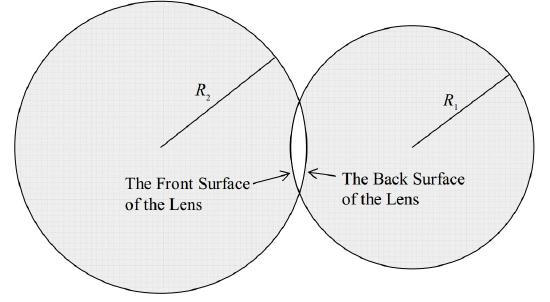
we can identify \(R_1\) as the radius of curvature of the front surface of the lens and \(R_2\) as the radius of curvature of the back surface of the lens.
The defining characteristic of a lens is a quantity called the focal length of the lens. At this point, I’m going to tell you how you can calculate a value for the focal length of a lens, based on the physical characteristics of the lens, before I even tell you what focal length means. (Don’t worry, though, we’ll get to the definition soon.) The lens-maker’s equation gives the reciprocal of the focal length in terms of the physical characteristics of the lens (and the medium in which the lens finds itself):
The Lens-Maker’s Equation:
\[\frac{1}{f}=(n-n_0) \Big(\frac{1}{R_1}+\frac{1}{R_2} \Big) \label{28-1} \]
where:
- \(f\) is the focal length of the lens,
- \(n\) is the index of refraction of the material of which the lens is made,
- \(n_o\) is the index of refraction of the medium surrounding the lens (\(n_o\) is typically 1.00 because the medium surrounding the lens is typically air),
- \(R_1\) is the radius of curvature of one of the surfaces of the lens, and,
- \(R_2\) is the radius of curvature of the other surface of the lens.
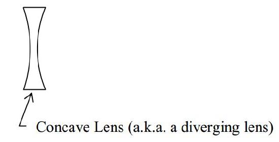
Before we move on from the lens-maker’s equation, I need to tell you about an algebraic sign convention for the R values. There are two kinds of spherical lens surfaces. One is the “curved out” kind possessed by any lens that is the intersection of two spheres. (This is the kind of lens that we have been talking about.) Such a lens is referred to as a convex lens (a.k.a. a converging lens) and each (“curved out”) surface is referred to as a convex surface. The radius of curvature \(R\) for a convex surface is, by convention, positive.
The other kind of lens surface is part of a sphere that does not enclose the lens itself. Such a surface is said to be “curved in” and is called a concave surface.
By convention, the absolute value of \(R\) for a concave surface is still the radius of the sphere whose surface coincides with that of the lens. But, the quantity \(R\) contains additional information in the form of a minus sign used to designate the fact that the surface of the lens is concave. \(R\) is still called the radius of curvature of the surface of the lens despite the fact that there is no such thing as a sphere whose radius is actually negative.
Summarizing, our convention for the radius of curvature of the surface of a lens is:
| Surface of Lens | Algebraic Sign of Radius of Curvature R |
|---|---|
Convex 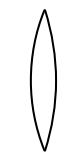 |
 |
Concave 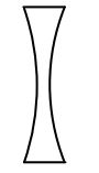 |
 |
So, what does a lens do? It refracts light at both surfaces. What’s special about a lens is the effect that it has on an infinite set of rays, collectively. We can characterize the operational effect of a lens in terms of the effect that it has on incoming rays that are all parallel to the principal axis of the lens. (The principal axis of a lens is an imaginary line that is perpendicular to the plane of the lens and passes through the center of the lens.) A converging lens causes all
such rays to pass through a single point on the other side of the lens. That point is the focal point \(F\) of the lens. Its distance from the lens is called the focal length \(f\) of the lens.
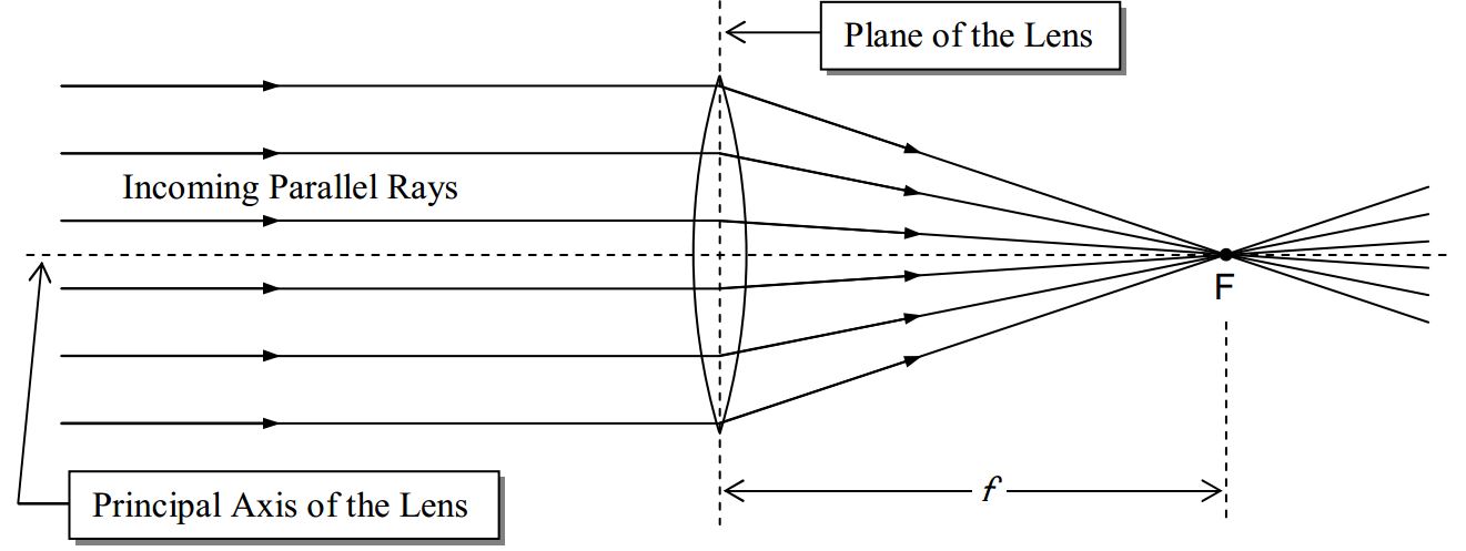
Note that in the diagram, we show the rays of light undergoing an abrupt change in direction at the plane of the lens. This is called the thin lens approximation and we will be using it in all our dealings with lenses. You know that the light is refracted twice in passing through a lens, once at the interface where it enters the lens medium, and again where it exits the lens medium. The two refractions together cause the incoming rays to travel in the directions in which they do travel. The thin lens approximation treats the pair of refractions as a single path change occurring at the plane of the lens. The thin lens approximation is good as long as the thickness of the lens is small compared to the focal length, the object distance, and the image distance.
Rays parallel to the principal axis of the lens that enter the lens from the opposite direction (opposite the direction of the rays discussed above) will also be caused to converge to a focal point on the other side of the lens. The two focal points are one and the same distance \(f\) from the plane of the lens.
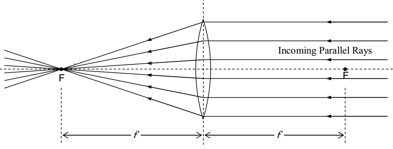
The two phenomena discussed above are reversible in the sense that rays of light coming from a point source, at either focal point, will result in parallel rays on the other side of the lens. Here we show that situation for the case of a point source at one of the focal points:
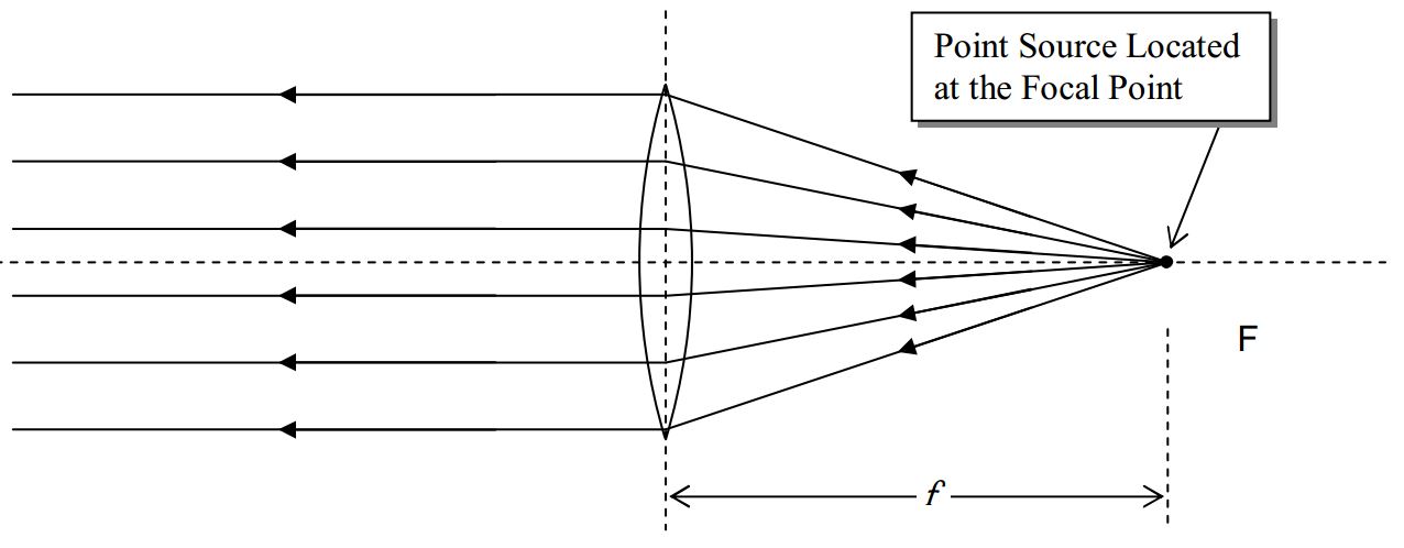
and here we show it for the case of a point source at the other focal point.
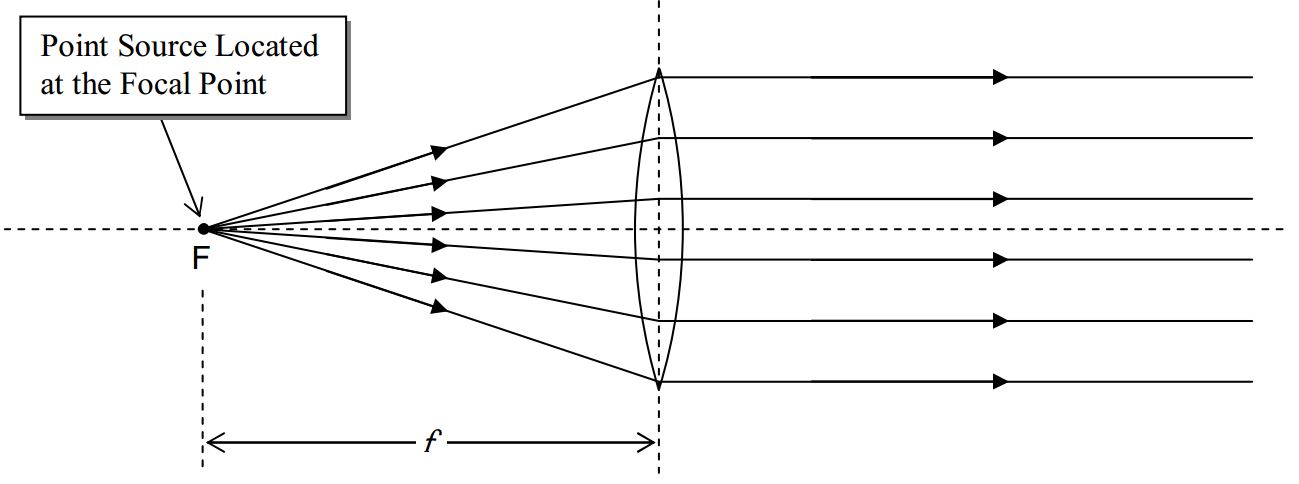
The important thing about this is that, any ray that passes through the focal point on its way to the lens is, after passing through the lens, going to be parallel to the principal axis of the lens.
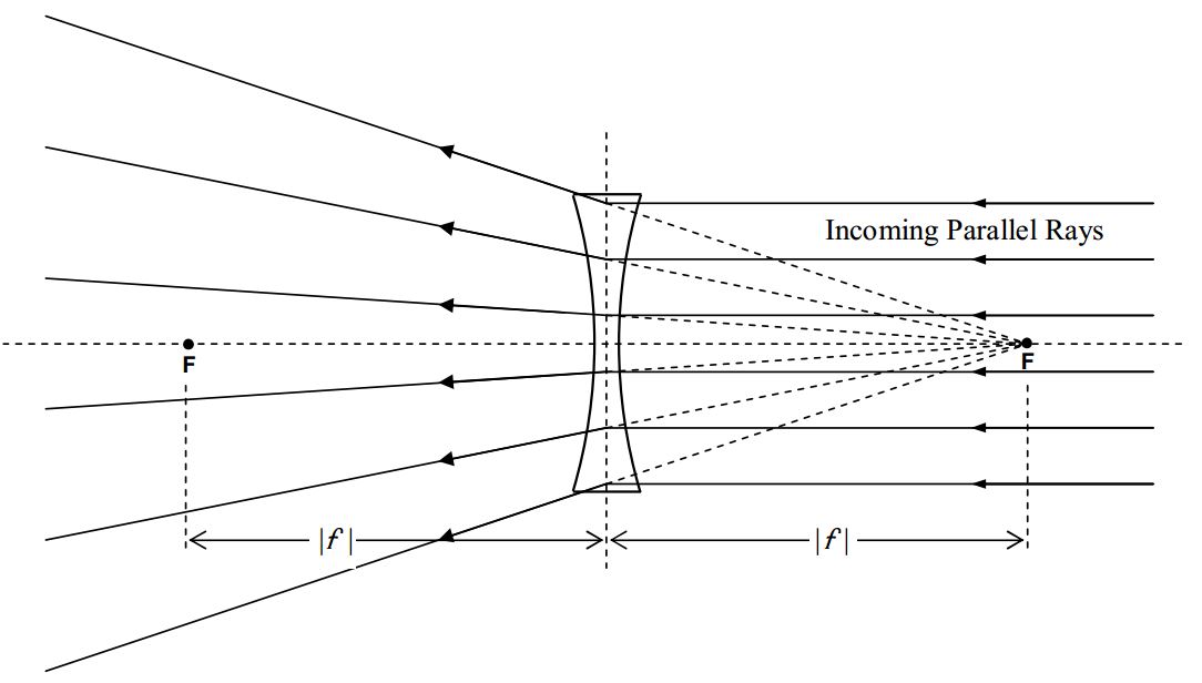
In the case of a diverging lens, incoming parallel rays are caused to diverge:
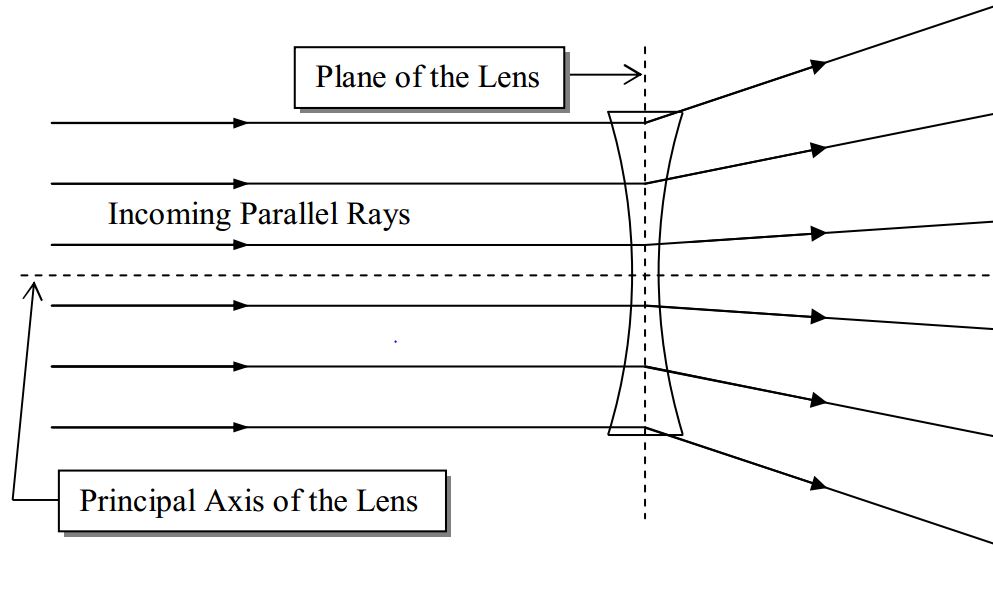
so that they travel along lines which trace-back shows,

all pass through one and the same point. That is, on passing through the lens, the once-parallel rays diverge as if they originated from a point. That point is known as the focal point of the diverging lens. The distance from the plane of the lens to the focal point is the magnitude of the focal length of the lens. But, by convention, the focal length of a diverging lens is negative. In other words, the focal length of a diverging lens is the negative of the distance from the plane of the lens to the focal point.
As in the case of the converging lens, there is another focal point on the other side of the lens, the same distance from the plane of the lens as the focal point discussed above:
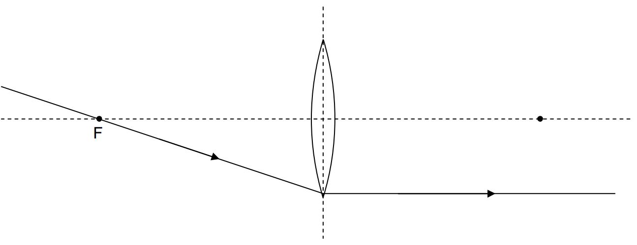
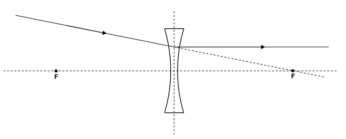
This effect is reversible in that any ray that is traveling through space on one side of the lens, and is headed directly toward the focal point on the other side of the lens, will, upon passing through the lens, become parallel to the principal axis of the lens.
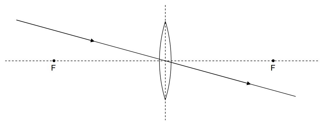
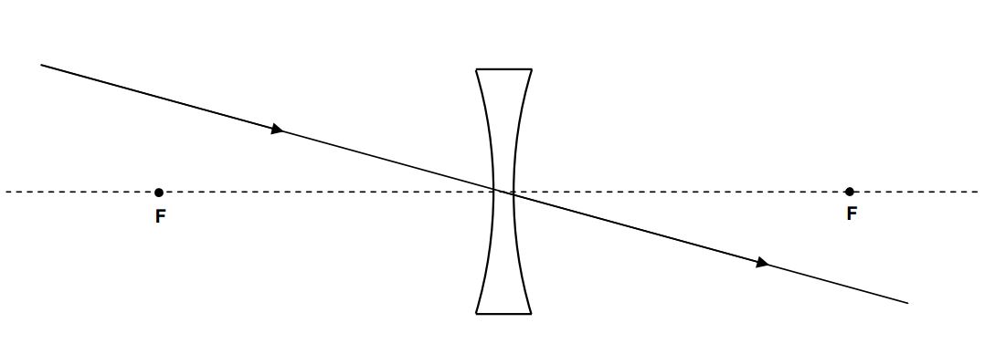
Our plan here is to use the facts about what a lens does to incoming rays of light that are parallel to the principal axis of a lens or are heading directly toward or away from a focal point, to determine where a lens will form an image of an object. Before we do that, I need to tell you one more thing about both kinds of thin spherical lenses. This last fact is a reminder that our whole discussion is an approximation that hinges on the fact that the lenses we are dealing with are indeed thin. Here’s the new fact: Any ray that is headed directly toward the center of a lens goes straight through. The justification is that at the center of the lens, the two surfaces of the lens are parallel. So, to the extent that they are parallel in a small region about the center of the lens, it is as if the light is passing through a thin piece of plate glass (or any transparent medium shaped like plate glass.) When light in air, is incident at some angle of incidence other than 0°, on plate glass, after it gets through both air/glass interfaces, the ray is parallel to the incoming ray. The amount by which the outgoing ray is shifted sideways, relative to the incoming ray, depends on how thick the plate is—the thinner the plate, the closer the outgoing ray is to being collinear with the incoming ray. In the thin lens approximation, we treat the outgoing ray as being exactly collinear with the incoming ray.
Using Ray Tracing Diagrams
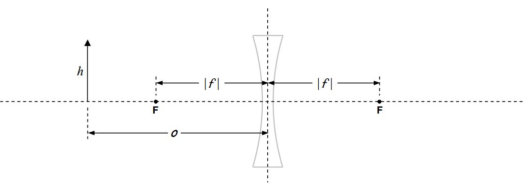
Given an object of height \(h\), the object position \(o\), and the focal length \(f\) of the lens with respect to which the object position is given, you need to be able to diagrammatically determine: where the image of that object will be formed by the lens, how big the image is, whether the image is erect (right side up) or inverted (upside down), and whether the image is real or virtual (these terms will be defined soon). Here’s how you do that for the case of a diverging lens of specified focal length for which the object distance \(o > |f |\):
Draw the plane of the lens and the principal axis of the lens. Draw the lens, but think of it as an icon, just telling you what kind of lens you are dealing with. As you proceed with the diagram be careful not to show rays changing direction at the surface of your icon. Also, make sure you draw a diverging lens if the focal length is negative. Measure off the distance |f | to both sides of the plane of the lens and draw the focal points. Measure off the object distance o from the plane of the lens, and, the height h of the object. Draw in the object.
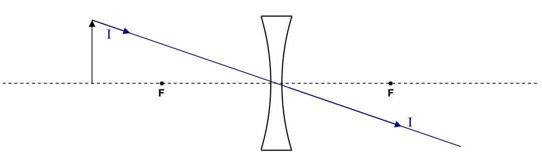
We determine the position of the image of the tip of the arrow by means of three principal rays. The three principal rays are rays on which the effect of the lens is easy to determine based on our understanding of what a lens does to incoming rays that are traveling toward the center of the lens, incoming rays that are traveling toward or away from a focal point, and incoming rays that are traveling directly toward the center of the lens. Let’s start with the easy one, Principal Ray I. It leaves the tip of the arrow and heads directly toward the center of the lens. It goes straight through.
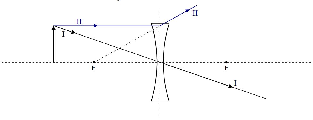
Next comes Principal Ray II. It comes in parallel to the principal axis of the lens, and, at the plane of the lens, jumps on a diverging line, which, if traced back, passes through the focal point on the same side of the lens as the object. Note the need for trace-back.
In the case of a diverging lens, Principal Ray III is the ray that, as it approaches the lens, is headed straight for the focal point on the other side of the lens. At the plane of the lens, Principal Ray III jumps onto a path that is parallel to the principal axis of the lens.
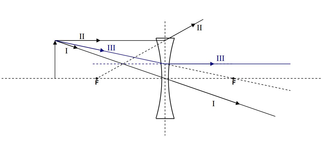
Note that, after passing through the lens, all three rays are diverging from each other. Trace-back yields the apparent point of origin of the rays, the image of the tip of the arrow. It is at the location where the three lines cross. (In practice, using a ruler and pencil, due to human error, the lines will cross at three different points. Consider these to be the vertices of a triangle and draw the tip of the arrow at what you judge to be the geometric center of the triangle.) Having located the image of the tip of the arrow, draw the shaft of the image of the arrow, showing that it extends from point of intersection, to the principal axis of the lens, and, that it is perpendicular to the principal axis of the lens.
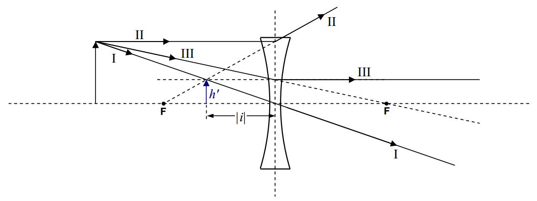
Measurements with a ruler yield the image height \(h′\) and the magnitude of the image distance \(|i|\). The image is said to be a virtual image. A virtual image of a point, is a point from which rays appear to come, as determined by trace-back, but, through which the rays do not all, actually pass. By convention, the image distance is negative when the image is on the same side of the lens as the object. A negative image distance also signifies a virtual image. Note that the image is erect. By convention, an erect image has a positive image height \(h′\). The magnification M is given by:
\[M=\frac{h'}{h} \nonumber \]
By convention, a positive value of \(M\) means the image is erect (right side up).
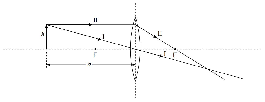
For the case of a converging lens, Principal Ray I is identical to the corresponding ray for the diverging lens. It starts out headed straight for the center of the lens, and, it goes straight through. Principal Ray II starts out the same way Principal Ray II did for the diverging lens—it comes in parallel to the principal axis of the lens—but, starting at the plane of the lens, rather than diverging, it is caused to converge to the extent that it passes through the focal point on the other side of the lens.
Principal Ray III, for a converging lens (with the object farther from the lens than the focal point is), passes through the focal point on the same side of the lens (the side of the lens the object is on) and then, when it gets to the plane of the lens, comes out parallel to the principal axis of the lens.
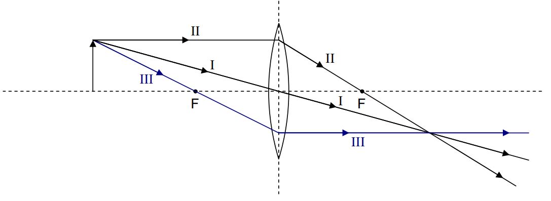
If you position yourself so that the rays, having passed through the lens, are coming at you, and, you are far enough away from the lens, you will again see the rays diverging from a point. But this time, all the rays actually go through that point. That is, the lens converges the rays to a point, and they don’t start diverging again until after they pass through that point. That point is the image of the tip of the arrow. It is a real image. You can tell because if you trace back the lines the rays are traveling along, you come to a point through which all the rays actually travel. Identifying the crossing point as the tip of the arrow, we draw the shaft and head of the arrow.
This time, the image is inverted. We can measure the length of the image and the distance of the image from the plane of the mirror. By convention, the image height is negative when the image is inverted, and, the image distance is positive when the image is on the side of the lens opposite that of the object. The magnification M is again given by
\[M=\frac{h'}{h}\label{28-2} \]
which, with \(h′\) being negative, turns out to be negative itself. This is consistent with the convention that a negative magnification means the image is inverted.
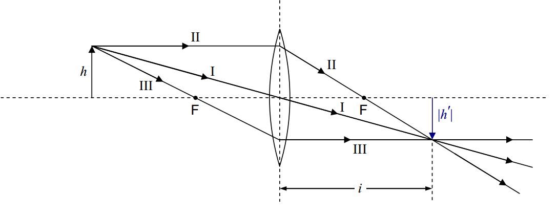
Principal Ray III is different for the converging lens when the object is closer to the plane of the lens than the focal point is:
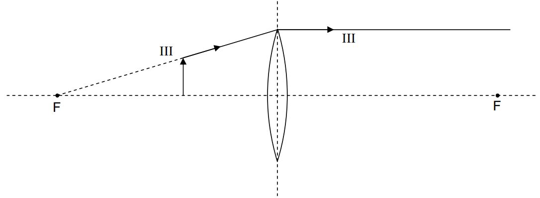
Principal Ray III, like every principal ray, starts at the tip of the object and travels toward the plane of the lens. In the case at hand, on its way to the plane of lens, Principal Ray III travels along a line that, if traced back, passes through the focal point on the same side of the lens as the object.
This concludes our discussion of the determination of image features and position by means of ray tracing. In closing this chapter, I summarize the algebraic sign conventions, in the form of a table:
| Physical Quantity | Symbol | Sign Convention |
|---|---|---|
| focal length | f |
+ for converging lens - for diverging lens |
| image distance | i |
+ for real image (on opposite side of lens as object) - for virtual image (on same side of lens as object) |
| image height | h' |
+ for erect image - for inverted image |
| magnification | M |
+ for erect image - for inverted image |