
20.1: Overview
- Page ID
- 14564

learning objectives
- Describe structure of an electrical circuit and identify elements of a direct current circuit
Overview
An electrical network is an interconnection of electrical elements such as resistors, inductors, capacitors, transmission lines, voltage sources, current sources and switches. An electrical circuit is a special type of network, one that has a closed loop giving a return path for the current. Electrical networks that consist only of sources (voltage or current), linear lumped elements (resistors, capacitors, inductors), and linear distributed elements (transmission lines) can be analyzed by algebraic and transform methods. A resistive circuit is a circuit containing only resistors and ideal current and voltage sources. Analysis of resistive circuits is less complicated than analysis of circuits containing capacitors and inductors. If the sources are constant (DC) sources, the result is a DC circuit. A network that contains active electronic components is known as an electronic circuit. Such networks are generally nonlinear and require more complex design and analysis tools.
Circuits: A brief introduction to electric circuits and current flow for introductory physics students.
Direct Current Circuits
Direct current (DC) is the unidirectional flow of electric charge. Direct current is produced by sources such as batteries, thermocouples, solar cells, and commutator-type electric machines of the dynamo type. Direct current may flow in a conductor such as a wire, but can also flow through semiconductors, insulators, or even through a vacuum as in electron or ion beams. The electric charge flows in a constant direction, distinguishing it from alternating current (AC). A term formerly used for direct current was galvanic current.
A direct current circuit is an electrical circuit that consists of any combination of constant voltage sources, constant current sources, and resistors. In this case, the circuit voltages and currents are independent of time. A particular circuit voltage or current does not depend on the past value of any circuit voltage or current. This implies that the system of equations that represent a DC circuit do not involve integrals or derivatives with respect to time. If a capacitor or inductor is added to a DC circuit, the resulting circuit is not, strictly speaking, a DC circuit. However, most such circuits have a DC solution. This solution gives the circuit voltages and currents when the circuit is in DC steady state. Such a circuit is represented by a system of differential equations. The solution to these equations usually contain a time varying or transient part as well as constant or steady state part. It is this steady state part that is the DC solution. In electronics, it is common to refer to a circuit that is powered by a DC voltage source such as a battery or the output of a DC power supply as a DC circuit even though what is meant is that the circuit is DC powered.
A simple DC circuit is illustrated in. In circuit diagrams such as this, electrical elements are represented by symbols and usually labeled with appropriate characteristics, such as the resistance r of a resistor. The electric potential and current may also be labeled at various points of the circuit. However, please be aware that circuit diagram conventions do differ among textbooks and subject fields, leading to different symbols being used for the same circuit elements.
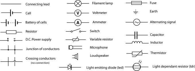
Example Circuit Element Symbols: A set of example circuit elements and their associated symbols commonly used in circuit diagrams.

A Simple Circuit: A simple DC circuit with a voltage source (V) and resistor (R). The current i flowing through the circuit is given by Ohm’s law.
Physical Laws Related to Circuit Analysis
A number of electrical laws apply to all electrical networks. These include Ohm’s law, which has been discussed in the “Resistance and Resistors” module, Kirchhoff’s current and voltage laws, which are covered in the “Kirchhoff’s Rules” module. The two Kirchoff laws along with the current-voltage characteristic (I-V curve) of each electrical element completely describe a circuit. With these, it is possible to calculate the electric potential and current at each point in the circuit. In addition, Norton’s theorem and Thévenin’s theorem are useful in analyzing complicated circuits.
Sources of EMF
Electromotive force (EMF) is the voltage voltage generated by a battery or by the magnetic force according to Faraday’s Law of Induction.
learning objectives
- Give examples of the devices that can provide the electromotive force
Electromotive Force
Electromotive force, also called EMF (denoted and measured in volts) refers to voltage generated by a battery or by the magnetic force according to Faraday’s Law of Induction, which states that a time varying magnetic field will induce an electric current.
Electromotive “force” is not considered a force (as force is measured in newtons) but a potential, or energy per unit of charge, measured in volts. Formally, EMF is classified as the external work expended per unit of charge to produce an electric potential difference across two open-circuited terminals. By separating positive and negative charges, electric potential difference is produced, generating an electric field. The created electrical potential difference drives current flow if a circuit is attached to the source of EMF. When current flows, however, the voltage across the terminals of the source of EMF is no longer the open-circuit value, due to voltage drops inside the device due to its internal resistance.
Devices that can provide EMF include electrochemical cells (batteries), thermoelectric devices, solar cells, electrical generators, transformers, and even Van de Graaff generators (examples shown in ).
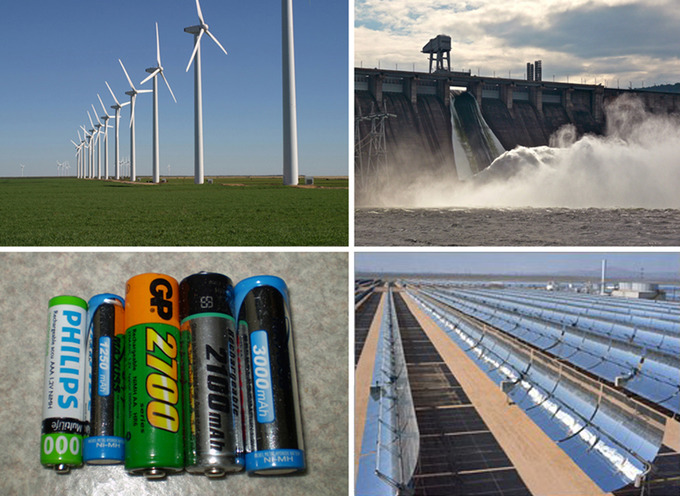
Examples of generators of electromotive force.: A variety of voltage sources (clockwise from top left): the Brazos Wind Farm in Fluvanna, Texas (credit: Leaflet, Wikimedia Commons); the Krasnoyarsk Dam in Russia (credit: Alex Polezhaev); a solar farm (credit: U.S. Department of Energy); and a group of nickel metal hydride batteries (credit: Tiaa Monto). The voltage output of each depends on its construction and load, and equals emf only if there is no load.
In the case of a battery, charge separation that gives rise to a voltage difference is accomplished by chemical reactions at the electrodes; voltaic cells can be thought of as having a “charge pump” of atomic dimensions at each electrode.
In the case of an electrical generator, a time-varying magnetic field inside the generator creates an electric field via electromagnetic induction, which in turn creates an energy difference between generator terminals. Charge separation takes place within the generator, with electrons flowing away from one terminal and toward the other, until, in the open-circuit case, sufficient electric field builds up to make further movement unfavorable. Again the EMF is countered by the electrical voltage due to charge separation. If a load is attached, this voltage can drive a current. The general principle governing the EMF in such electrical machines is Faraday’s law of Induction.
In nature, EMF is generated whenever magnetic field fluctuations occur through a surface. An example of this is the varying Earth magnetic field during a geomagnetic storm, acting on anything on the surface of the planet, like an extended electrical grid.
Key Points
- Direct current ( DC ) is the unidirectional flow of electric charge. Direct current is produced by sources such as batteries, thermocouples, solar cells, and commutator-type electric machines of the dynamo type.
- A direct current circuit is an electrical circuit that consists of constant voltage sources, constant current sources, and resistors. It is common to refer to a circuit that is powered by a DC voltage source as a DC circuit even though what is meant is that the circuit is DC powered.
- A number of electrical laws apply to all electrical networks: Ohm ‘s law, Kirchhoff’s current and voltage laws, Norton’s theorem, and Thévenin’s theorem. With these, it is possible to calculate the electric potential and current at each point in the circuit.
- EMF is classified as the external work expended per unit of charge to produce an electric potential difference across two open-circuited terminals.
- Devices that can provide EMF include electrochemical cells, thermoelectric devices, solar cells, electrical generators, transformers, and even Van de Graaff generators.
- In nature, EMF is generated whenever magnetic field fluctuations occur through a surface.
Key Terms
- current-voltage characteristic: A current–voltage characteristic or I–V curve (current–voltage curve) is a relationship between the electric current through a circuit, device, or material, and the corresponding voltage, or potential difference across it.
- electrical circuit: An interconnection of electrical elements such as resistors, inductors, capacitors, transmission lines, voltage sources, current sources and switches that has a closed loop giving a return path for the current.
- direct current: An electric current in which the electrons flow in one direction, but may vary with time.
- battery: A device that produces electricity by a chemical reaction between two substances.
- electromotive force: (EMF)—The voltage generated by a battery or by the magnetic force according to Faraday’s Law. It is measured in units of volts, not newtons, and thus, is not actually a force.
- Faraday’s law of induction: Is a basic law of electromagnetism that predicts how a magnetic field will interact with an electric circuit to produce an electromotive force.
LICENSES AND ATTRIBUTIONS
CC LICENSED CONTENT, SHARED PREVIOUSLY
- Curation and Revision. Provided by: Boundless.com. License: CC BY-SA: Attribution-ShareAlike
CC LICENSED CONTENT, SPECIFIC ATTRIBUTION
- FHSST Physics/Electricity/Flow of Charge. Provided by: Wikibooks. Located at: en.wikibooks.org/wiki/FHSST_Physics/Electricity/Flow_of_Charge. License: CC BY-SA: Attribution-ShareAlike
- Provided by: Light and Matter. Located at: http://lightandmatter.com/simplej.pdf. License: CC BY-SA: Attribution-ShareAlike
- Direct current. Provided by: Wikipedia. Located at: en.Wikipedia.org/wiki/Direct_current. License: CC BY-SA: Attribution-ShareAlike
- Physics with Calculus/Electromagnetism/Current and Circuits. Provided by: Wikibooks. Located at: en.wikibooks.org/wiki/Physics_with_Calculus/Electromagnetism/Current_and_Circuits. License: CC BY-SA: Attribution-ShareAlike
- FHSST Physics/Electricity/Circuits. Provided by: Wikibooks. Located at: en.wikibooks.org/wiki/FHSST_Physics/Electricity/Circuits. License: CC BY-SA: Attribution-ShareAlike
- Electrical circuit. Provided by: Wikipedia. Located at: en.Wikipedia.org/wiki/Electrical_circuit. License: CC BY-SA: Attribution-ShareAlike
- Direct current. Provided by: Wikipedia. Located at: en.Wikipedia.org/wiki/Direct_current. License: CC BY-SA: Attribution-ShareAlike
- Electrical circuit. Provided by: Wikipedia. Located at: en.Wikipedia.org/wiki/Electrical_circuit. License: CC BY-SA: Attribution-ShareAlike
- electrical circuit. Provided by: Wikipedia. Located at: en.Wikipedia.org/wiki/electrical%20circuit. License: CC BY-SA: Attribution-ShareAlike
- current-voltage characteristic. Provided by: Wikipedia. Located at: en.Wikipedia.org/wiki/current-voltage%20characteristic. License: CC BY-SA: Attribution-ShareAlike
- direct current. Provided by: Wiktionary. Located at: en.wiktionary.org/wiki/direct_current. License: CC BY-SA: Attribution-ShareAlike
- Circuits. Located at: http://www.youtube.com/watch?v=j5XxZ10Alig. License: Public Domain: No Known Copyright. License Terms: Standard YouTube license
- Provided by: Wikipedia. Located at: en.Wikipedia.org/w/index.php?title=File:Ohm's_Law_with_Voltage_source.svg&page=1. License: Public Domain: No Known Copyright
- Circuit Symbols for A-level-OCR-Physics A. Provided by: Wikibooks. Located at: en.wikibooks.org/wiki/File:Circuit_Symbols_for_A-level-OCR-Physics_A.png. License: CC BY-SA: Attribution-ShareAlike
- Oka Kurniawan, Physics. September 17, 2013. Provided by: OpenStax CNX. Located at: http://cnx.org/content/m42357/latest/?collection=col11428/latest. License: CC BY: Attribution
- Voltage source. Provided by: Wikipedia. Located at: en.Wikipedia.org/wiki/Voltage_source. License: CC BY-SA: Attribution-ShareAlike
- Electromotive force. Provided by: Wikipedia. Located at: en.Wikipedia.org/wiki/Electromotive_force. License: CC BY-SA: Attribution-ShareAlike
- Voltage source. Provided by: Wikipedia. Located at: en.Wikipedia.org/wiki/Voltage_source. License: CC BY-SA: Attribution-ShareAlike
- A-level Physics (Advancing Physics)/Voltage. Provided by: Wikibooks. Located at: en.wikibooks.org/wiki/A-level_Physics_(Advancing_Physics)/Voltage. License: CC BY-SA: Attribution-ShareAlike
- Oka Kurniawan, Physics. September 17, 2013. Provided by: OpenStax CNX. Located at: http://cnx.org/content/m42357/latest/?collection=col11428/latest. License: CC BY: Attribution
- Current source. Provided by: Wikipedia. Located at: en.Wikipedia.org/wiki/Current_source. License: CC BY-SA: Attribution-ShareAlike
- IB Physics/Electric Currents. Provided by: Wikibooks. Located at: en.wikibooks.org/wiki/IB_Physics/Electric_Currents. License: CC BY-SA: Attribution-ShareAlike
- A-level Physics/Electrons, Waves and Photons/D.C.ncircuits. Provided by: Wikibooks. Located at: en.wikibooks.org/wiki/A-level_Physics/Electrons,_Waves_and_Photons/D.C._circuits. License: CC BY-SA: Attribution-ShareAlike
- Voltage source. Provided by: Wikipedia. Located at: en.Wikipedia.org/wiki/Voltage_source. License: CC BY-SA: Attribution-ShareAlike
- Electromotive force. Provided by: Wikipedia. Located at: en.Wikipedia.org/wiki/Electromotive_force. License: CC BY-SA: Attribution-ShareAlike
- Oka Kurniawan, Physics. September 17, 2013. Provided by: OpenStax CNX. Located at: http://cnx.org/content/m42357/latest/?collection=col11428/latest. License: CC BY: Attribution
- Boundless. Provided by: Boundless Learning. Located at: www.boundless.com//physics/definition/faraday-s-law-of-induction--3. License: CC BY-SA: Attribution-ShareAlike
- battery. Provided by: Wiktionary. Located at: en.wiktionary.org/wiki/battery. License: CC BY-SA: Attribution-ShareAlike
- electromotive force. Provided by: Wikipedia. Located at: en.Wikipedia.org/wiki/electromotive%20force. License: CC BY-SA: Attribution-ShareAlike
- Circuits. Located at: http://www.youtube.com/watch?v=j5XxZ10Alig. License: Public Domain: No Known Copyright. License Terms: Standard YouTube license
- Provided by: Wikipedia. Located at: en.Wikipedia.org/w/index.php?title=File:Ohm's_Law_with_Voltage_source.svg&page=1. License: Public Domain: No Known Copyright
- Circuit Symbols for A-level-OCR-Physics A. Provided by: Wikibooks. Located at: en.wikibooks.org/wiki/File:Circuit_Symbols_for_A-level-OCR-Physics_A.png. License: CC BY-SA: Attribution-ShareAlike
- OpenStax College, College Physics. November 3, 2012. Provided by: OpenStax CNX. Located at: http://cnx.org/content/m42357/latest/?collection=col11406/1.7. License: CC BY: Attribution