
10.2: Parallel and Series Circuits
- Page ID
- 965

In section 9.1, we limited ourselves to relatively simple circuits, essentially nothing more than a battery and a single lightbulb. The purpose of this chapter is to introduce you to more complex circuits, containing multiple resistors or voltage sources in series, in parallel, or both.
9.2.1 Schematics
I see a chess position; Kasparov sees an interesting Ruy Lopez variation. To the uninitiated a schematic may look as unintelligible as Mayan hieroglyphs, but even a little bit of eye training can go a long way toward making its meaning leap off the page. A schematic is a stylized and simplified drawing of a circuit. The purpose is to eliminate as many irrelevant features as possible, so that the relevant ones are easier to pick out.
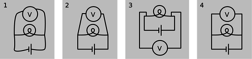
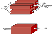
a / 1. Wrong: The shapes of the wires are irrelevant. 2. Wrong: Right angles should be used. 3. Wrong: A simple pattern is made to look unfamiliar and complicated. 4. Right.
An example of an irrelevant feature is the physical shape, length, and diameter of a wire. In nearly all circuits, it is a good approximation to assume that the wires are perfect conductors, so that any piece of wire uninterrupted by other components has constant voltage throughout it. Changing the length of the wire, for instance, does not change this fact. (Of course if we used miles and miles of wire, as in a telephone line, the wire's resistance would start to add up, and its length would start to matter.) The shapes of the wires are likewise irrelevant, so we draw them with standardized, stylized shapes made only of vertical and horizontal lines with right-angle bends in them. This has the effect of making similar circuits look more alike and helping us to recognize familiar patterns, just as words in a newspaper are easier to recognize than handwritten ones. Figure a shows some examples of these concepts.
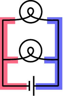
b / The two shaded areas shaped like the letter “E” are both regions of constant voltage.
The most important first step in learning to read schematics is to learn to recognize contiguous pieces of wire which must have constant voltage throughout. In figure b, for example, the two shaded E-shaped pieces of wire must each have constant voltage. This focuses our attention on two of the main unknowns we'd like to be able to predict: the voltage of the left-hand E and the voltage of the one on the right.
9.2.2 Parallel resistances and the junction rule
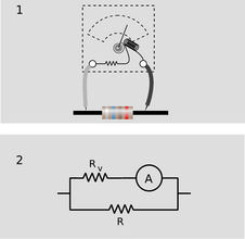
One of the simplest examples to analyze is the parallel resistance circuit, of which figure b was an example. In general we may have unequal resistances \(R_1\) and \(R_2\), as in c/1. Since there are only two constant-voltage areas in the circuit, c/2, all three components have the same voltage difference across them. A battery normally succeeds in maintaining the voltage differences across itself for which it was designed, so the voltage drops \(\Delta V_1\) and \(\Delta V_2\) across the resistors must both equal the voltage of the battery:
Each resistance thus feels the same voltage difference as if it was the only one in the circuit, and Ohm's law tells us that the amount of current flowing through each one is also the same as it would have been in a one-resistor circuit. This is why household electrical circuits are wired in parallel. We want every appliance to work the same, regardless of whether other appliances are plugged in or unplugged, turned on or switched off. (The electric company doesn't use batteries of course, but our analysis would be the same for any device that maintains a constant voltage.)
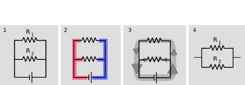
c / 1. Two resistors in parallel. 2. There are two constant-voltage areas. 3. The current that comes out of the battery splits between the two resistors, and later reunites. 4. The two resistors in parallel can be treated as a single resistor with a smaller resistance value.
Of course the electric company can tell when we turn on every light in the house. How do they know? The answer is that we draw more current. Each resistance draws a certain amount of current, and the amount that has to be supplied is the sum of the two individual currents. The current is like a river that splits in half, c/3, and then reunites. The total current is
This is an example of a general fact called the junction rule:
In any circuit that is not storing or releasing charge, conservation of charge implies that the total current flowing out of any junction must be the same as the total flowing in.
Coming back to the analysis of our circuit, we apply Ohm's law to each resistance, resulting in
As far as the electric company is concerned, your whole house is just one resistor with some resistance \(R\), called the equivalent resistance. They would write Ohm's law as
from which we can determine the equivalent resistance by comparison with the previous expression:
[equivalent resistance of two resistors in parallel]
Two resistors in parallel, c/4, are equivalent to a single resistor with a value given by the above equation.
| Example 10: Two lamps on the same household circuit |
|---|
| \(\triangleright\) You turn on two lamps that are on the same household circuit. Each one has a resistance of 1 ohm. What is the equivalent resistance, and how does the power dissipation compare with the case of a single lamp? \(\triangleright\) The equivalent resistance of the two lamps in parallel is \[\begin{align*} R &= \left(\frac{1}{ R_1}+\frac{1}{ R_2}\right)^{-1} \\ &= \left(\frac{1}{1\ \Omega}+\frac{1}{1\ \Omega}\right)^{-1} \\ &= \left(1\ \Omega^{-1} + 1\ \Omega^{-1}\right)^{-1} \\ &= \left(2\ \Omega^{-1}\right)^{-1} \\ &= \text{0.5}\ \Omega \end{align*}\] The voltage difference across the whole circuit is always the 110 V set by the electric company (it's alternating current, but that's irrelevant). The resistance of the whole circuit has been cut in half by turning on the second lamp, so a fixed amount of voltage will produce twice as much current. Twice the current flowing across the same voltage difference means twice as much power dissipation, which makes sense. |
The cutting in half of the resistance surprises many students, since we are “adding more resistance” to the circuit by putting in the second lamp. Why does the equivalent resistance come out to be less than the resistance of a single lamp? This is a case where purely verbal reasoning can be misleading. A resistive circuit element, such as the filament of a lightbulb, is neither a perfect insulator nor a perfect conductor. Instead of analyzing this type of circuit in terms of “resistors,” i.e., partial insulators, we could have spoken of “conductors.” This example would then seem reasonable, since we “added more conductance,” but one would then have the incorrect expectation about the case of resistors in series, discussed in the following section.
Perhaps a more productive way of thinking about it is to use mechanical intuition. By analogy, your nostrils resist the flow of air through them, but having two nostrils makes it twice as easy to breathe.
| Example 11: Three resistors in parallel |
|---|
| \(\triangleright\) What happens if we have three or more resistors in parallel?
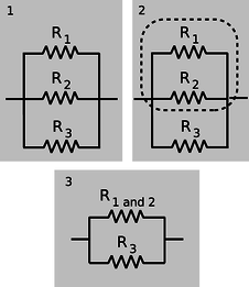
d / Three resistors in parallel.
\(\triangleright\) This is an important example, because the solution involves an important technique for understanding circuits: breaking them down into smaller parts and them simplifying those parts. In the circuit d/1, with three resistors in parallel, we can think of two of the resistors as forming a single big resistor, d/2, with equivalent resistance \[\begin{equation*} R_{12} = \left(\frac{1}{ R_1}+\frac{1}{ R_2}\right)^{-1} . \end{equation*}\] We can then simplify the circuit as shown in d/3, so that it contains only two resistances. The equivalent resistance of the whole circuit is then given by \[\begin{equation*} R_{123} = \left(\frac{1}{ R_{12}}+\frac{1}{ R_3}\right)^{-1} . \end{equation*}\] Substituting for \(R_{12}\) and simplifying, we find the result \[\begin{equation*} R_{123} = \left(\frac{1}{ R_1}+\frac{1}{ R_2}+\frac{1}{ R_3}\right)^{-1} , \end{equation*}\] which you probably could have guessed. The interesting point here is the divide-and-conquer concept, not the mathematical result. |
| Example 12: An arbitrary number of identical resistors in parallel |
|---|
| \(\triangleright\) What is the resistance of \(N\) identical resistors in parallel? \(\triangleright\) Generalizing the results for two and three resistors, we have \[\begin{equation*} R_{N} = \left(\frac{1}{ R_1}+\frac{1}{ R_2}+...\right)^{-1} , \end{equation*}\] where “...” means that the sum includes all the resistors. If all the resistors are identical, this becomes \[\begin{align*} R_{N} &= \left(\frac{ N}{ R}\right)^{-1} \\ &= \frac{ R}{ N} \end{align*}\] |
| Example 13: Dependence of resistance on cross-sectional area |
|---|
|
e / Uniting four resistors in parallel is equivalent to making a single resistor with the same length but four times the cross-sectional area. The result is to make a resistor with one quarter the resistance.
We have alluded briefly to the fact that an object's electrical resistance depends on its size and shape, but now we are ready to begin making more mathematical statements about it. As suggested by figure e, increasing a resistors's cross-sectional area is equivalent to adding more resistors in parallel, which will lead to an overall decrease in resistance. Any real resistor with straight, parallel sides can be sliced up into a large number of pieces, each with cross-sectional area of, say, 1 \(\mu \text{m}^2\). The number, \(N\), of such slices is proportional to the total cross-sectional area of the resistor, and by application of the result of the previous example we therefore find that the resistance of an object is inversely proportional to its cross-sectional area.
f / A fat pipe has less resistance than a skinny pipe.
An analogous relationship holds for water pipes, which is why high-flow trunk lines have to have large cross-sectional areas. To make lots of water (current) flow through a skinny pipe, we'd need an impractically large pressure (voltage) difference. |
| Example 14: Incorrect readings from a voltmeter |
|---|
|
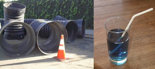
g / A voltmeter is really an ammeter with an internal resistor. When we measure the voltage difference across a resistor, 1, we are really constructing a parallel resistance circuit, 2.
A voltmeter is really just an ammeter with an internal resistor, and we use a voltmeter in parallel with the thing that we're trying to measure the voltage difference across. This means that any time we measure the voltage drop across a resistor, we're essentially putting two resistors in parallel. The ammeter inside the voltmeter can be ignored for the purpose of analyzing what how current flows in the circuit, since it is essentially just some coiled-up wire with a very low resistance. Now if we are carrying out this measurement on a resistor that is part of a larger circuit, we have changed the behavior of the circuit through our act of measuring. It is as though we had modified the circuit by replacing the resistance \(R\) with the smaller equivalent resistance of \(R\) and \(R_v\) in parallel. It is for this reason that voltmeters are built with the largest possible internal resistance. As a numerical example, if we use a voltmeter with an internal resistance of 1 \(M\Omega \) to measure the voltage drop across a one-ohm resistor, the equivalent resistance is 0.999999 \(\Omega \), which is not different enough to make any difference. But if we tried to use the same voltmeter to measure the voltage drop across a \(2-M\Omega \) resistor, we would be reducing the resistance of that part of the circuit by a factor of three, which would produce a drastic change in the behavior of the whole circuit. |
This is the reason why you can't use a voltmeter to measure the voltage difference between two different points in mid-air, or between the ends of a piece of wood. This is by no means a stupid thing to want to do, since the world around us is not a constant-voltage environment, the most extreme example being when an electrical storm is brewing. But it will not work with an ordinary voltmeter because the resistance of the air or the wood is many gigaohms. The effect of waving a pair of voltmeter probes around in the air is that we provide a reuniting path for the positive and negative charges that have been separated --- through the voltmeter itself, which is a good conductor compared to the air. This reduces to zero the voltage difference we were trying to measure.
In general, a voltmeter that has been set up with an open circuit (or a very large resistance) between its probes is said to be “floating.” An old-fashioned analog voltmeter of the type described here will read zero when left floating, the same as when it was sitting on the shelf. A floating digital voltmeter usually shows an error message.
9.2.3 Series resistances
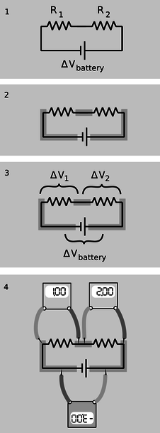
h / 1. A battery drives current through two resistors in series. 2. There are three constant-voltage regions. 3. The three voltage differences are related. 4. If the meter crab-walks around the circuit without flipping over or crossing its legs, the resulting voltages have plus and minus signs that make them add up to zero.
The two basic circuit layouts are parallel and series, so a pair of resistors in series, h/1, is another of the most basic circuits we can make. By conservation of charge, all the current that flows through one resistor must also flow through the other (as well as through the battery):
The only way the information about the two resistance values is going to be useful is if we can apply Ohm's law, which will relate the resistance of each resistor to the current flowing through it and the voltage difference across it. Figure h/2 shows the three constant-voltage areas. Voltage differences are more physically significant than voltages, so we define symbols for the voltage differences across the two resistors in figure h/3.
We have three constant-voltage areas, with symbols for the difference in voltage between every possible pair of them. These three voltage differences must be related to each other. It is as though I tell you that Fred is a foot taller than Ginger, Ginger is a foot taller than Sally, and Fred is two feet taller than Sally. The information is redundant, and you really only needed two of the three pieces of data to infer the third. In the case of our voltage differences, we have
The absolute value signs are because of the ambiguity in how we define our voltage differences. If we reversed the two probes of the voltmeter, we would get a result with the opposite sign. Digital voltmeters will actually provide a minus sign on the screen if the wire connected to the “V” plug is lower in voltage than the one connected to the “COM” plug. Analog voltmeters pin the needle against a peg if you try to use them to measure negative voltages, so you have to fiddle to get the leads connected the right way, and then supply any necessary minus sign yourself.
Figure h/4 shows a standard way of taking care of the ambiguity in signs. For each of the three voltage measurements around the loop, we keep the same probe (the darker one) on the clockwise side. It is as though the voltmeter was sidling around the circuit like a crab, without ever “crossing its legs.” With this convention, the relationship among the voltage drops becomes
or, in more symmetrical form,
More generally, this is known as the loop rule for analyzing circuits:
Assuming the standard convention for plus and minus signs, the sum of the voltage drops around any closed loop in a circuit must be zero.
Looking for an exception to the loop rule would be like asking for a hike that would be downhill all the way and that would come back to its starting point!
For the circuit we set out to analyze, the equation
can now be rewritten by applying Ohm's law to each resistor:
The currents are the same, so we can factor them out:
and this is the same result we would have gotten if we had been analyzing a one-resistor circuit with resistance \(R_1+R_2\). Thus the equivalent resistance of resistors in series equals the sum of their resistances.
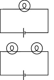
| Example 15: Two lightbulbs in series |
|---|
| \(\triangleright\) If two identical lightbulbs are placed in series, how do their brightnesses compare with the brightness of a single bulb?
i / Example 15.
\(\triangleright\) Taken as a whole, the pair of bulbs act like a doubled resistance, so they will draw half as much current from the wall. Each bulb will be dimmer than a single bulb would have been. The total power dissipated by the circuit is \(I\Delta V\). The voltage drop across the whole circuit is the same as before, but the current is halved, so the two-bulb circuit draws half as much total power as the one-bulb circuit. Each bulb draws one-quarter of the normal power. Roughly speaking, we might expect this to result in one quarter the light being produced by each bulb, but in reality lightbulbs waste quite a high percentage of their power in the form of heat and wavelengths of light that are not visible (infrared and ultraviolet). Less light will be produced, but it's hard to predict exactly how much less, since the efficiency of the bulbs will be changed by operating them under different conditions. |
| Example 16: More than two equal resistances in series |
|---|
| By straightforward application of the divide-and-conquer technique discussed in the previous section, we find that the equivalent resistance of \(N\) identical resistances \(R\) in series will be \(NR\). |
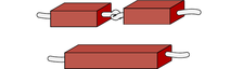
| Example 17: Dependence of resistance on length |
|---|
| In the previous section, we proved that resistance is inversely proportional to cross-sectional area. By equivalent reason about resistances in series, we find that resistance is proportional to length. Analogously, it is harder to blow through a long straw than through a short one.
j / Doubling the length of a resistor is like putting two resistors in series. The resistance is doubled. |
Putting the two arguments together, we find that the resistance of an object with straight, parallel sides is given by
The proportionality constant is called the resistivity, and it depends only on the substance of which the object is made. A resistivity measurement could be used, for instance, to help identify a sample of an unknown substance.
| Example 18: Choice of high voltage for power lines |
|---|
| Thomas Edison got involved in a famous technological controversy over the voltage difference that should be used for electrical power lines. At this time, the public was unfamiliar with electricity, and easily scared by it. The president of the United States, for instance, refused to have electrical lighting in the White House when it first became commercially available because he considered it unsafe, preferring the known fire hazard of oil lamps to the mysterious dangers of electricity. Mainly as a way to overcome public fear, Edison believed that power should be transmitted using small voltages, and he publicized his opinion by giving demonstrations at which a dog was lured into position to be killed by a large voltage difference between two sheets of metal on the ground. (Edison's opponents also advocated alternating current rather than direct current, and AC is more dangerous than DC as well. As we will discuss later, AC can be easily stepped up and down to the desired voltage level using a device called a transformer.) Now if we want to deliver a certain amount of power \(P_L\) to a load such as an electric lightbulb, we are constrained only by the equation \(P_{L} = I\Delta V_L\). We can deliver any amount of power we wish, even with a low voltage, if we are willing to use large currents. Modern electrical distribution networks, however, use dangerously high voltage differences of tens of thousands of volts. Why did Edison lose the debate? It boils down to money. The electric company must deliver the amount of power \(P_L\) desired by the customer through a transmission line whose resistance \(R_T\) is fixed by economics and geography. The same current flows through both the load and the transmission line, dissipating power usefully in the former and wastefully in the latter. The efficiency of the system is \[\begin{align*} \text{efficiency} &= \frac{\text{power paid for by the customer}} {\text{power paid for by the utility}} \\ &= \frac{ P_{L}}{ P_L+ P_{T}} \\ &= \frac{1}{1+ P_{T}/ P_L} \end{align*}\] Putting ourselves in the shoes of the electric company, we wish to get rid of the variable \(P_T\), since it is something we control only indirectly by our choice of \(\Delta V_T\) and \(I\). Substituting \(P_{T}= I\Delta V_T\), we find \[\begin{equation*} \text{efficiency} = \frac{1} {1+\frac{ I \Delta V_T}{ P_L}} \end{equation*}\] We assume the transmission line (but not necessarily the load) is ohmic, so substituting \(\Delta V_T=IR_T\) gives \[\begin{equation*} efficiency = \frac{1}{1+\frac{I^2R_T}{P_L}} \end{equation*}\] This quantity can clearly be maximized by making \(I\) as small as possible, since we will then be dividing by the smallest possible quantity on the bottom of the fraction. A low-current circuit can only deliver significant amounts of power if it uses high voltages, which is why electrical transmission systems use dangerous high voltages. |
| Example 19: Getting killed by your ammeter |
|---|
| As with a voltmeter, an ammeter can give erroneous readings if it is used in such a way that it changes the behavior the circuit. An ammeter is used in series, so if it is used to measure the current through a resistor, the resistor's value will effectively be changed to \(R+ R_a\), where \(R_a\) is the resistance of the ammeter. Ammeters are designed with very low resistances in order to make it unlikely that \(R+ R_a\) will be significantly different from \(R\). In fact, the real hazard is death, not a wrong reading! Virtually the only circuits whose resistances are significantly less than that of an ammeter are those designed to carry huge currents. An ammeter inserted in such a circuit can easily melt. When I was working at a laboratory funded by the Department of Energy, we got periodic bulletins from the DOE safety office about serious accidents at other sites, and they held a certain ghoulish fascination. One of these was about a DOE worker who was completely incinerated by the explosion created when he inserted an ordinary Radio Shack ammeter into a high-current circuit. Later estimates showed that the heat was probably so intense that the explosion was a ball of plasma --- a gas so hot that its atoms have been ionized. |
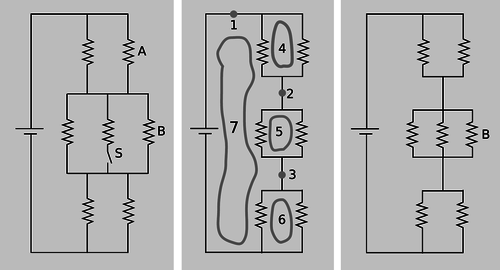
k / Example 20.
| Example 20: A complicated circuit |
|---|
| \(\triangleright\) All seven resistors in the left-hand panel of figure k are identical. Initially, the switch S is open as shown in the figure, and the current through resistor A is \(I_\text{o}\). The switch is then closed. Find the current through resistor B, after the switch is closed, in terms of \(I_\text{o}\). \(\triangleright\) The second panel shows the circuit redrawn for simplicity, in the initial condition with the switch open. When the switch is open, no current can flow through the central resistor, so we may as well ignore it. I've also redrawn the junctions, without changing what's connected to what. This is the kind of mental rearranging that you'll eventually learn to do automatically from experience with analyzing circuits. The redrawn version makes it easier to see what's happening with the current. Charge is conserved, so any charge that flows past point 1 in the circuit must also flow past points 2 and 3. This would have been harder to reason about by applying the junction rule to the original version, which appears to have nine separate junctions. In the new version, it's also clear that the circuit has a great deal of symmetry. We could flip over each parallel pair of identical resistors without changing what's connected to what, so that makes it clear that the voltage drops and currents must be equal for the members of each pair. We can also prove this by using the loop rule. The loop rule says that the two voltage drops in loop 4 must be equal, and similarly for loops 5 and 6. Since the resistors obey Ohm's law, equal voltage drops across them also imply equal currents. That means that when the current at point 1 comes to the top junction, exactly half of it goes through each resistor. Then the current reunites at 2, splits between the next pair, and so on. We conclude that each of the six resistors in the circuit experiences the same voltage drop and the same current. Applying the loop rule to loop 7, we find that the sum of the three voltage drops across the three left-hand resistors equals the battery's voltage, \(V\), so each resistor in the circuit experiences a voltage drop \(V/3\). Letting \(R\) stand for the resistance of one of the resistors, we find that the current through resistor B, which is the same as the currents through all the others, is given by \(I_\text{o}=V/3R\). We now pass to the case where the switch is closed, as shown in the third panel. The battery's voltage is the same as before, and each resistor's resistance is the same, so we can still use the same symbols \(V\) and \(R\) for them. It is no longer true, however, that each resistor feels a voltage drop \(V/3\). The equivalent resistance of the whole circuit is \(R/2+R/3+R/2=4R/3\), so the total current drawn from the battery is \(3V/4R\). In the middle group of resistors, this current is split three ways, so the new current through B is \((1/3)(3V/4R)=V/4R=3I_\text{o}/4\). Interpreting this result, we see that it comes from two effects that partially cancel. Closing the switch reduces the equivalent resistance of the circuit by giving charge another way to flow, and increases the amount of current drawn from the battery. Resistor B, however, only gets a 1/3 share of this greater current, not 1/2. The second effect turns out to be bigger than the first, and therefore the current through resistor B is lessened over all. |
Discussion Question
◊ We have stated the loop rule in a symmetric form where a series of voltage drops adds up to zero. To do this, we had to define a standard way of connecting the voltmeter to the circuit so that the plus and minus signs would come out right. Suppose we wish to restate the junction rule in a similar symmetric way, so that instead of equating the current coming in to the current going out, it simply states that a certain sum of currents at a junction adds up to zero. What standard way of inserting the ammeter would we have to use to make this work?
Contributors
Benjamin Crowell (Fullerton College). Conceptual Physics is copyrighted with a CC-BY-SA license.