
18.2: Lever Law
- Page ID
- 24537
\( \newcommand{\vecs}[1]{\overset { \scriptstyle \rightharpoonup} {\mathbf{#1}} } \)
\( \newcommand{\vecd}[1]{\overset{-\!-\!\rightharpoonup}{\vphantom{a}\smash {#1}}} \)
\( \newcommand{\dsum}{\displaystyle\sum\limits} \)
\( \newcommand{\dint}{\displaystyle\int\limits} \)
\( \newcommand{\dlim}{\displaystyle\lim\limits} \)
\( \newcommand{\id}{\mathrm{id}}\) \( \newcommand{\Span}{\mathrm{span}}\)
( \newcommand{\kernel}{\mathrm{null}\,}\) \( \newcommand{\range}{\mathrm{range}\,}\)
\( \newcommand{\RealPart}{\mathrm{Re}}\) \( \newcommand{\ImaginaryPart}{\mathrm{Im}}\)
\( \newcommand{\Argument}{\mathrm{Arg}}\) \( \newcommand{\norm}[1]{\| #1 \|}\)
\( \newcommand{\inner}[2]{\langle #1, #2 \rangle}\)
\( \newcommand{\Span}{\mathrm{span}}\)
\( \newcommand{\id}{\mathrm{id}}\)
\( \newcommand{\Span}{\mathrm{span}}\)
\( \newcommand{\kernel}{\mathrm{null}\,}\)
\( \newcommand{\range}{\mathrm{range}\,}\)
\( \newcommand{\RealPart}{\mathrm{Re}}\)
\( \newcommand{\ImaginaryPart}{\mathrm{Im}}\)
\( \newcommand{\Argument}{\mathrm{Arg}}\)
\( \newcommand{\norm}[1]{\| #1 \|}\)
\( \newcommand{\inner}[2]{\langle #1, #2 \rangle}\)
\( \newcommand{\Span}{\mathrm{span}}\) \( \newcommand{\AA}{\unicode[.8,0]{x212B}}\)
\( \newcommand{\vectorA}[1]{\vec{#1}} % arrow\)
\( \newcommand{\vectorAt}[1]{\vec{\text{#1}}} % arrow\)
\( \newcommand{\vectorB}[1]{\overset { \scriptstyle \rightharpoonup} {\mathbf{#1}} } \)
\( \newcommand{\vectorC}[1]{\textbf{#1}} \)
\( \newcommand{\vectorD}[1]{\overrightarrow{#1}} \)
\( \newcommand{\vectorDt}[1]{\overrightarrow{\text{#1}}} \)
\( \newcommand{\vectE}[1]{\overset{-\!-\!\rightharpoonup}{\vphantom{a}\smash{\mathbf {#1}}}} \)
\( \newcommand{\vecs}[1]{\overset { \scriptstyle \rightharpoonup} {\mathbf{#1}} } \)
\(\newcommand{\longvect}{\overrightarrow}\)
\( \newcommand{\vecd}[1]{\overset{-\!-\!\rightharpoonup}{\vphantom{a}\smash {#1}}} \)
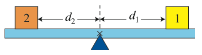
\(\newcommand{\avec}{\mathbf a}\) \(\newcommand{\bvec}{\mathbf b}\) \(\newcommand{\cvec}{\mathbf c}\) \(\newcommand{\dvec}{\mathbf d}\) \(\newcommand{\dtil}{\widetilde{\mathbf d}}\) \(\newcommand{\evec}{\mathbf e}\) \(\newcommand{\fvec}{\mathbf f}\) \(\newcommand{\nvec}{\mathbf n}\) \(\newcommand{\pvec}{\mathbf p}\) \(\newcommand{\qvec}{\mathbf q}\) \(\newcommand{\svec}{\mathbf s}\) \(\newcommand{\tvec}{\mathbf t}\) \(\newcommand{\uvec}{\mathbf u}\) \(\newcommand{\vvec}{\mathbf v}\) \(\newcommand{\wvec}{\mathbf w}\) \(\newcommand{\xvec}{\mathbf x}\) \(\newcommand{\yvec}{\mathbf y}\) \(\newcommand{\zvec}{\mathbf z}\) \(\newcommand{\rvec}{\mathbf r}\) \(\newcommand{\mvec}{\mathbf m}\) \(\newcommand{\zerovec}{\mathbf 0}\) \(\newcommand{\onevec}{\mathbf 1}\) \(\newcommand{\real}{\mathbb R}\) \(\newcommand{\twovec}[2]{\left[\begin{array}{r}#1 \\ #2 \end{array}\right]}\) \(\newcommand{\ctwovec}[2]{\left[\begin{array}{c}#1 \\ #2 \end{array}\right]}\) \(\newcommand{\threevec}[3]{\left[\begin{array}{r}#1 \\ #2 \\ #3 \end{array}\right]}\) \(\newcommand{\cthreevec}[3]{\left[\begin{array}{c}#1 \\ #2 \\ #3 \end{array}\right]}\) \(\newcommand{\fourvec}[4]{\left[\begin{array}{r}#1 \\ #2 \\ #3 \\ #4 \end{array}\right]}\) \(\newcommand{\cfourvec}[4]{\left[\begin{array}{c}#1 \\ #2 \\ #3 \\ #4 \end{array}\right]}\) \(\newcommand{\fivevec}[5]{\left[\begin{array}{r}#1 \\ #2 \\ #3 \\ #4 \\ #5 \\ \end{array}\right]}\) \(\newcommand{\cfivevec}[5]{\left[\begin{array}{c}#1 \\ #2 \\ #3 \\ #4 \\ #5 \\ \end{array}\right]}\) \(\newcommand{\mattwo}[4]{\left[\begin{array}{rr}#1 \amp #2 \\ #3 \amp #4 \\ \end{array}\right]}\) \(\newcommand{\laspan}[1]{\text{Span}\{#1\}}\) \(\newcommand{\bcal}{\cal B}\) \(\newcommand{\ccal}{\cal C}\) \(\newcommand{\scal}{\cal S}\) \(\newcommand{\wcal}{\cal W}\) \(\newcommand{\ecal}{\cal E}\) \(\newcommand{\coords}[2]{\left\{#1\right\}_{#2}}\) \(\newcommand{\gray}[1]{\color{gray}{#1}}\) \(\newcommand{\lgray}[1]{\color{lightgray}{#1}}\) \(\newcommand{\rank}{\operatorname{rank}}\) \(\newcommand{\row}{\text{Row}}\) \(\newcommand{\col}{\text{Col}}\) \(\renewcommand{\row}{\text{Row}}\) \(\newcommand{\nul}{\text{Nul}}\) \(\newcommand{\var}{\text{Var}}\) \(\newcommand{\corr}{\text{corr}}\) \(\newcommand{\len}[1]{\left|#1\right|}\) \(\newcommand{\bbar}{\overline{\bvec}}\) \(\newcommand{\bhat}{\widehat{\bvec}}\) \(\newcommand{\bperp}{\bvec^\perp}\) \(\newcommand{\xhat}{\widehat{\xvec}}\) \(\newcommand{\vhat}{\widehat{\vvec}}\) \(\newcommand{\uhat}{\widehat{\uvec}}\) \(\newcommand{\what}{\widehat{\wvec}}\) \(\newcommand{\Sighat}{\widehat{\Sigma}}\) \(\newcommand{\lt}{<}\) \(\newcommand{\gt}{>}\) \(\newcommand{\amp}{&}\) \(\definecolor{fillinmathshade}{gray}{0.9}\)Let’s consider a uniform rigid beam of mass \(m_{b}\) balanced on a pivot near the center of mass of the beam. We place two objects 1 and 2 of masses \(m_{1}\) and \(m_{2}\) on the beam, at distances \(d_{1}\) and \(d_{2}\) respectively from the pivot, so that the beam is static (that is, the beam is not rotating. See Figure 18.1.) We shall neglect the thickness of the beam and take the pivot point to be the center of mass.
Let’s consider the forces acting on the beam. The earth attracts the beam downward. This gravitational force acts on every atom in the beam, but we can summarize its action by stating that the gravitational force \(m_{b} \overrightarrow{\mathbf{g}}\) is concentrated at a point in the beam called the center of gravity of the beam, which is identical to the center of mass of the uniform beam. There is also a contact force \(\overrightarrow{\mathbf{F}}_{\text {pivot }}\) between the pivot and the beam, acting upwards on the beam at the pivot point. The objects 1 and 2 exert normal forces downwards on the beam, \(\overrightarrow{\mathbf{N}}_{1, b} \equiv \overrightarrow{\mathbf{N}}_{1}\) and \(\overrightarrow{\mathbf{N}}_{2, b} \equiv \overrightarrow{\mathbf{N}}_{2}\), with magnitudes \(N_{1}, \text { and } N_{2}\) respectively. Note that the normal forces are not the gravitational forces acting on the objects, but contact forces between the beam and the objects. (In this case, they are mathematically the same, due to the horizontal configuration of the beam and the fact that all objects are in static equilibrium.) The distances \(d_{1} \text { and } d_{2}\) are called the moment arms with respect to the pivot point for the forces \(\overrightarrow{\mathbf{N}}_{1} \text { and } \overrightarrow{\mathbf{N}}_{2}\), respectively. The force diagram on the beam is shown in Figure 18.2. Note that the pivot force \(\overrightarrow{\mathbf{F}}_{\text {pivot }}\) and the force of gravity \(m_{b} \overrightarrow{\mathbf{g}}\) each has a zero moment arm about the pivot point.
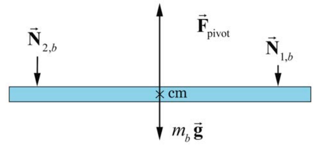
Because we assume the beam is not moving, the sum of the forces in the vertical direction acting on the beam is therefore zero,
\[F_{\text {pivot }}-m_{b} g-N_{1}-N_{2}=0 \nonumber \]
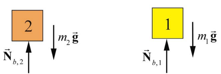
The force diagrams on the objects are shown in Figure 18.3. Note the magnitude of the normal forces on the objects are also \(N_{1} \text { and } N_{2}\) since these are each part of an action- reaction pair, \(\overrightarrow{\mathbf{N}}_{1, b}=-\overrightarrow{\mathbf{N}}_{b, 1}, \text { and } \overrightarrow{\mathbf{N}}_{2, b}=-\overrightarrow{\mathbf{N}}_{b, 2}\)
The condition that the forces sum to zero is not sufficient to completely predict the motion of the beam. All we can deduce is that the center of mass of the system is at rest (or moving with a uniform velocity). In order for the beam not to rotate the sum of the torques about any point must be zero. In particular the sum of the torques about the pivot point must be zero. Because the moment arm of the gravitational force and the pivot force is zero, only the two normal forces produce a torque on the beam. If we choose out of the page as positive direction for the torque (or equivalently counterclockwise rotations are positive) then the condition that the sum of the torques about the pivot point is zero becomes
\[d_{2} N_{2}-d_{1} N_{1}=0 \nonumber \]
The magnitudes of the two torques about the pivot point are equal, a condition known as the lever law.
Lever Law
A beam of length l is balanced on a pivot point that is placed directly beneath the center of mass of the beam. The beam will not undergo rotation if the product of the normal force with the moment arm to the pivot is the same for each body,
\[d_{1} N_{1}=d_{2} N_{2} \nonumber \]
Example \(\PageIndex{1}\): Lever Law
Suppose a uniform beam of length \(l=1.0 \mathrm{m}\) and mass \(m_{\mathrm{B}}=2.0 \mathrm{kg}\) is balanced on a pivot point, placed directly beneath the center of the beam. We place body 1 with mass \(m_{1}=0.3 \mathrm{kg}\) a distance \(d_{1}=0.4 \mathrm{m}\) to the right of the pivot point, and a second body 2 with \(m_{2}=0.6 \mathrm{kg}\) a distance \(d_{2}\) to the left of the pivot point, such that the beam neither translates nor rotates. (a) What is the force \(\overrightarrow{\mathbf{F}}_{\text {pivot }}\) that the pivot exerts on the beam? (b) What is the distance \(d_{2}\) that maintains static equilibrium?
Solution
a) By Newton’s Third Law, the beam exerts equal and opposite normal forces of magnitude \(N_{1}\) on body 1, and \(N_{2}\) on body 2. The condition for force equilibrium applied separately to the two bodies yields
\[N_{1}-m_{1} g=0 \nonumber \]
\[N_{2}-m_{2} g=0 \nonumber \]
Thus the total force acting on the beam is zero,
\[F_{\text {pivot }}-\left(m_{b}+m_{1}+m_{2}\right) g=0 \nonumber \]
and the pivot force is
\[\begin{aligned}
F_{\text {pivot }} &=\left(m_{b}+m_{1}+m_{2}\right) g \\
&=(2.0 \mathrm{kg}+0.3 \mathrm{kg}+0.6 \mathrm{kg})\left(9.8 \mathrm{m} \cdot \mathrm{s}^{-2}\right)=2.8 \times 10^{1} \mathrm{N}
\end{aligned} \nonumber \]
b) We can compute the distance \(d_{2}\) from the Lever Law,
\[d_{2}=\frac{d_{1} N_{1}}{N_{2}}=\frac{d_{1} m_{1} g}{m_{2} g}=\frac{d_{1} m_{1}}{m_{2}}=\frac{(0.4 \mathrm{m})(0.3 \mathrm{kg})}{0.6 \mathrm{kg}}=0.2 \mathrm{m} \nonumber \]