
13.4: Refraction
- Page ID
- 984

\( \newcommand{\vecs}[1]{\overset { \scriptstyle \rightharpoonup} {\mathbf{#1}} } \)
\( \newcommand{\vecd}[1]{\overset{-\!-\!\rightharpoonup}{\vphantom{a}\smash {#1}}} \)
\( \newcommand{\dsum}{\displaystyle\sum\limits} \)
\( \newcommand{\dint}{\displaystyle\int\limits} \)
\( \newcommand{\dlim}{\displaystyle\lim\limits} \)
\( \newcommand{\id}{\mathrm{id}}\) \( \newcommand{\Span}{\mathrm{span}}\)
( \newcommand{\kernel}{\mathrm{null}\,}\) \( \newcommand{\range}{\mathrm{range}\,}\)
\( \newcommand{\RealPart}{\mathrm{Re}}\) \( \newcommand{\ImaginaryPart}{\mathrm{Im}}\)
\( \newcommand{\Argument}{\mathrm{Arg}}\) \( \newcommand{\norm}[1]{\| #1 \|}\)
\( \newcommand{\inner}[2]{\langle #1, #2 \rangle}\)
\( \newcommand{\Span}{\mathrm{span}}\)
\( \newcommand{\id}{\mathrm{id}}\)
\( \newcommand{\Span}{\mathrm{span}}\)
\( \newcommand{\kernel}{\mathrm{null}\,}\)
\( \newcommand{\range}{\mathrm{range}\,}\)
\( \newcommand{\RealPart}{\mathrm{Re}}\)
\( \newcommand{\ImaginaryPart}{\mathrm{Im}}\)
\( \newcommand{\Argument}{\mathrm{Arg}}\)
\( \newcommand{\norm}[1]{\| #1 \|}\)
\( \newcommand{\inner}[2]{\langle #1, #2 \rangle}\)
\( \newcommand{\Span}{\mathrm{span}}\) \( \newcommand{\AA}{\unicode[.8,0]{x212B}}\)
\( \newcommand{\vectorA}[1]{\vec{#1}} % arrow\)
\( \newcommand{\vectorAt}[1]{\vec{\text{#1}}} % arrow\)
\( \newcommand{\vectorB}[1]{\overset { \scriptstyle \rightharpoonup} {\mathbf{#1}} } \)
\( \newcommand{\vectorC}[1]{\textbf{#1}} \)
\( \newcommand{\vectorD}[1]{\overrightarrow{#1}} \)
\( \newcommand{\vectorDt}[1]{\overrightarrow{\text{#1}}} \)
\( \newcommand{\vectE}[1]{\overset{-\!-\!\rightharpoonup}{\vphantom{a}\smash{\mathbf {#1}}}} \)
\( \newcommand{\vecs}[1]{\overset { \scriptstyle \rightharpoonup} {\mathbf{#1}} } \)
\(\newcommand{\longvect}{\overrightarrow}\)
\( \newcommand{\vecd}[1]{\overset{-\!-\!\rightharpoonup}{\vphantom{a}\smash {#1}}} \)
\(\newcommand{\avec}{\mathbf a}\) \(\newcommand{\bvec}{\mathbf b}\) \(\newcommand{\cvec}{\mathbf c}\) \(\newcommand{\dvec}{\mathbf d}\) \(\newcommand{\dtil}{\widetilde{\mathbf d}}\) \(\newcommand{\evec}{\mathbf e}\) \(\newcommand{\fvec}{\mathbf f}\) \(\newcommand{\nvec}{\mathbf n}\) \(\newcommand{\pvec}{\mathbf p}\) \(\newcommand{\qvec}{\mathbf q}\) \(\newcommand{\svec}{\mathbf s}\) \(\newcommand{\tvec}{\mathbf t}\) \(\newcommand{\uvec}{\mathbf u}\) \(\newcommand{\vvec}{\mathbf v}\) \(\newcommand{\wvec}{\mathbf w}\) \(\newcommand{\xvec}{\mathbf x}\) \(\newcommand{\yvec}{\mathbf y}\) \(\newcommand{\zvec}{\mathbf z}\) \(\newcommand{\rvec}{\mathbf r}\) \(\newcommand{\mvec}{\mathbf m}\) \(\newcommand{\zerovec}{\mathbf 0}\) \(\newcommand{\onevec}{\mathbf 1}\) \(\newcommand{\real}{\mathbb R}\) \(\newcommand{\twovec}[2]{\left[\begin{array}{r}#1 \\ #2 \end{array}\right]}\) \(\newcommand{\ctwovec}[2]{\left[\begin{array}{c}#1 \\ #2 \end{array}\right]}\) \(\newcommand{\threevec}[3]{\left[\begin{array}{r}#1 \\ #2 \\ #3 \end{array}\right]}\) \(\newcommand{\cthreevec}[3]{\left[\begin{array}{c}#1 \\ #2 \\ #3 \end{array}\right]}\) \(\newcommand{\fourvec}[4]{\left[\begin{array}{r}#1 \\ #2 \\ #3 \\ #4 \end{array}\right]}\) \(\newcommand{\cfourvec}[4]{\left[\begin{array}{c}#1 \\ #2 \\ #3 \\ #4 \end{array}\right]}\) \(\newcommand{\fivevec}[5]{\left[\begin{array}{r}#1 \\ #2 \\ #3 \\ #4 \\ #5 \\ \end{array}\right]}\) \(\newcommand{\cfivevec}[5]{\left[\begin{array}{c}#1 \\ #2 \\ #3 \\ #4 \\ #5 \\ \end{array}\right]}\) \(\newcommand{\mattwo}[4]{\left[\begin{array}{rr}#1 \amp #2 \\ #3 \amp #4 \\ \end{array}\right]}\) \(\newcommand{\laspan}[1]{\text{Span}\{#1\}}\) \(\newcommand{\bcal}{\cal B}\) \(\newcommand{\ccal}{\cal C}\) \(\newcommand{\scal}{\cal S}\) \(\newcommand{\wcal}{\cal W}\) \(\newcommand{\ecal}{\cal E}\) \(\newcommand{\coords}[2]{\left\{#1\right\}_{#2}}\) \(\newcommand{\gray}[1]{\color{gray}{#1}}\) \(\newcommand{\lgray}[1]{\color{lightgray}{#1}}\) \(\newcommand{\rank}{\operatorname{rank}}\) \(\newcommand{\row}{\text{Row}}\) \(\newcommand{\col}{\text{Col}}\) \(\renewcommand{\row}{\text{Row}}\) \(\newcommand{\nul}{\text{Nul}}\) \(\newcommand{\var}{\text{Var}}\) \(\newcommand{\corr}{\text{corr}}\) \(\newcommand{\len}[1]{\left|#1\right|}\) \(\newcommand{\bbar}{\overline{\bvec}}\) \(\newcommand{\bhat}{\widehat{\bvec}}\) \(\newcommand{\bperp}{\bvec^\perp}\) \(\newcommand{\xhat}{\widehat{\xvec}}\) \(\newcommand{\vhat}{\widehat{\vvec}}\) \(\newcommand{\uhat}{\widehat{\uvec}}\) \(\newcommand{\what}{\widehat{\wvec}}\) \(\newcommand{\Sighat}{\widehat{\Sigma}}\) \(\newcommand{\lt}{<}\) \(\newcommand{\gt}{>}\) \(\newcommand{\amp}{&}\) \(\definecolor{fillinmathshade}{gray}{0.9}\)Economists normally consider free markets to be the natural way of judging the monetary value of something, but social scientists also use questionnaires to gauge the relative value of privileges, disadvantages, or possessions that cannot be bought or sold. They ask people to imagine that they could trade one thing for another and ask which they would choose. One interesting result is that the average light-skinned person in the U.S. would rather lose an arm than suffer the racist treatment routinely endured by African-Americans. Even more impressive is the value of sight. Many prospective parents can imagine without too much fear having a deaf child, but would have a far more difficult time coping with raising a blind one.
So great is the value attached to sight that some have imbued it with mystical aspects. Joan of Arc saw visions, and my college has a “vision statement.” Christian fundamentalists who perceive a conflict between evolution and their religion have claimed that the eye is such a perfect device that it could never have arisen through a process as helter-skelter as evolution, or that it could not have evolved because half of an eye would be useless. In fact, the structure of an eye is fundamentally dictated by physics, and it has arisen separately by evolution somewhere between eight and 40 times, depending on which biologist you ask. We humans have a version of the eye that can be traced back to the evolution of a light-sensitive “eye spot” on the head of an ancient invertebrate. A sunken pit then developed so that the eye would only receive light from one direction, allowing the organism to tell where the light was coming from. (Modern flatworms have this type of eye.) The top of the pit then became partially covered, leaving a hole, for even greater directionality (as in the nautilus). At some point the cavity became filled with jelly, and this jelly finally became a lens, resulting in the general type of eye that we share with the bony fishes and other vertebrates. Far from being a perfect device, the vertebrate eye is marred by a serious design flaw due to the lack of planning or intelligent design in evolution: the nerve cells of the retina and the blood vessels that serve them are all in front of the light-sensitive cells, blocking part of the light. Squids and other molluscs, whose eyes evolved on a separate branch of the evolutionary tree, have a more sensible arrangement, with the light-sensitive cells out in front.
12.4.1 Refraction
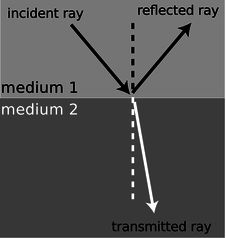
The fundamental physical phenomenon at work in the eye is that when light crosses a boundary between two media (such as air and the eye's jelly), part of its energy is reflected, but part passes into the new medium. In the ray model of light, we describe the original ray as splitting into a reflected ray and a transmitted one (the one that gets through the boundary). Of course the reflected ray goes in a direction that is different from that of the original one, according to the rules of reflection we have already studied. More surprisingly --- and this is the crucial point for making your eye focus light --- the transmitted ray is bent somewhat as well. This bending phenomenon is called refraction. The origin of the word is the same as that of the word “fracture,” i.e., the ray is bent or “broken.” (Keep in mind, however, that light rays are not physical objects that can really be “broken.”) Refraction occurs with all waves, not just light waves.
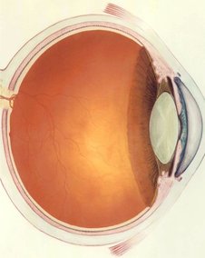
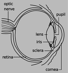
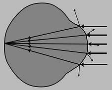
The actual anatomy of the eye, Figure \(\PageIndex{2}\), is quite complex, but in essence it is very much like every other optical device based on refraction. The rays are bent when they pass through the front surface of the eye, Figure \(\PageIndex{3}\). Rays that enter farther from the central axis are bent more, with the result that an image is formed on the retina. There is only one slightly novel aspect of the situation. In most human-built optical devices, such as a movie projector, the light is bent as it passes into a lens, bent again as it reemerges, and then reaches a focus beyond the lens. In the eye, however, the “screen” is inside the eye, so the rays are only refracted once, on entering the jelly, and never emerge again.
A common misconception is that the “lens” of the eye is what does the focusing. All the transparent parts of the eye are made of fairly similar stuff, so the dramatic change in medium is when a ray crosses from the air into the eye (at the outside surface of the cornea). This is where nearly all the refraction takes place. The lens medium differs only slightly in its optical properties from the rest of the eye, so very little refraction occurs as light enters and exits the lens. The lens, whose shape is adjusted by muscles attached to it, is only meant for fine-tuning the focus to form images of near or far objects.
Refractive Properties of Media
What are the rules governing refraction? The first thing to observe is that just as with reflection, the new, bent part of the ray lies in the same plane as the normal (perpendicular) and the incident ray, Figure \(\PageIndex{4}\).
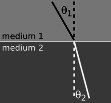
If you try shooting a beam of light at the boundary between two substances, say water and air, you'll find that regardless of the angle at which you send in the beam, the part of the beam in the water is always closer to the normal line, Figure \(\PageIndex{5}\).
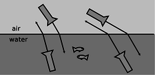
It doesn't matter if the ray is entering the water or leaving, so refraction is symmetric with respect to time-reversal, Figure \(\PageIndex{6}\).
If, instead of water and air, you try another combination of substances, say plastic and gasoline, again you'll find that the ray's angle with respect to the normal is consistently smaller in one and larger in the other. Also, we find that if substance A has rays closer to normal than in B, and B has rays closer to normal than in C, then A has rays closer to normal than C. This means that we can rank-order all materials according to their refractive properties. Isaac Newton did so, including in his list many amusing substances, such as “Danzig vitriol” and “a pseudo-topazius, being a natural, pellucid, brittle, hairy stone, of a yellow color.” Several general rules can be inferred from such a list:
- Vacuum lies at one end of the list. In refraction across the interface between vacuum and any other medium, the other medium has rays closer to the normal.
- Among gases, the ray gets closer to the normal if you increase the density of the gas by pressurizing it more.
- The refractive properties of liquid mixtures and solutions vary in a smooth and systematic manner as the proportions of the mixture are changed.
- Denser substances usually, but not always, have rays closer to the normal.
The second and third rules provide us with a method for measuring the density of an unknown sample of gas, or the concentration of a solution. The latter technique is very commonly used, and the CRC Handbook of Physics and Chemistry, for instance, contains extensive tables of the refractive properties of sugar solutions, cat urine, and so on.
Snell's Law
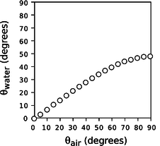
The numerical rule governing refraction was discovered by Snell, who must have collected experimental data something like what is shown on this graph and then attempted by trial and error to find the right equation. The equation he came up with was
\[ \frac{\sin\theta_1}{\sin\theta_2} = \text{constant} .\]
The value of the constant would depend on the combination of media used. For instance, any one of the data points in the graph would have sufficed to show that the constant was 1.3 for an air-water interface (taking air to be substance 1 and water to be substance 2).
Snell further found that if media A and B gave a constant \(K_{AB}\) and media B and C gave a constant \(K_{BC}\), then refraction at an interface between A and C would be described by a constant equal to the product, \(K_{AC}=K_{AB}K_{BC}\). This is exactly what one would expect if the constant depended on the ratio of some number characterizing one medium to the number characteristic of the second medium. This number is called the index of refraction of the medium, written as \(n\) in equations. Since measuring the angles would only allow him to determine the ratio of the indices of refraction of two media, Snell had to pick some medium and define it as having \(n=1\). He chose to define vacuum as having \(n=1\). (The index of refraction of air at normal atmospheric pressure is 1.0003, so for most purposes it is a good approximation to assume that air has \(n=1\).) He also had to decide which way to define the ratio, and he chose to define it so that media with their rays closer to the normal would have larger indices of refraction. This had the advantage that denser media would typically have higher indices of refraction, and for this reason the index of refraction is also referred to as the optical density. Written in terms of indices of refraction, Snell's equation becomes
\[ \frac{\sin\theta_1}{\sin\theta_2} = \frac{n_2}{n_1} , \]
but rewriting it in the form
\[ n_1 \sin \theta_1=n_2 \sin \theta_2 \]
[relationship between angles of rays at the interface between media with indices of refraction \(n_1\) and \(n_2\); angles are defined with respect to the normal] makes us less likely to get the 1's and 2's mixed up, so this the way most people remember Snell's law. A few indices of refraction are given in the back of the book.
- What would the graph look like for two substances with the same index of refraction?
- Based on the graph, when does refraction at an air-water interface change the direction of a ray most strongly?
(answer in the back of the PDF version of the book)
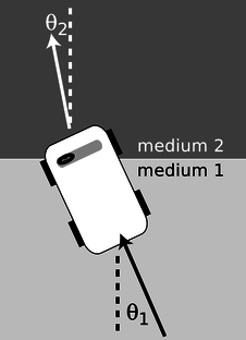
A submarine shines its searchlight up toward the surface of the water. What is the angle \(\alpha \) shown in Figure \(\PageIndex{8}\)?
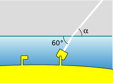
Solution
The tricky part is that Snell's law refers to the angles with respect to the normal. Forgetting this is a very common mistake. The beam is at an angle of \(30°\) with respect to the normal in the water. Let's refer to the air as medium 1 and the water as 2. Solving Snell's law for \(\theta_1\), we find
\[ \theta_1 = \sin^{-1}\left(\frac{n_2}{n_1}\sin\theta_2\right) . \]
As mentioned above, air has an index of refraction very close to 1, and water's is about 1.3, so we find \(\theta_1=40°\). The angle \(\alpha \) is therefore \(50°\).
What neither Snell nor Newton knew was that there is a very simple interpretation of the index of refraction. This may come as a relief to the reader who is taken aback by the complex reasoning involving proportionalities that led to its definition. Later experiments showed that the index of refraction of a medium was inversely proportional to the speed of light in that medium. Since \(c\) is defined as the speed of light in vacuum, and \(n=1\) is defined as the index of refraction of vacuum, we have
\[ n=\frac{c}{v} .\]
[\(n=\) medium's index of refraction, \(v=\) speed of light in that medium, \(c=\) speed of light in a vacuum]
Many textbooks start with this as the definition of the index of refraction, although that approach makes the quantity's name somewhat of a mystery, and leaves students wondering why \(c/v\) was used rather than \(v/c\). It should also be noted that measuring angles of refraction is a far more practical method for determining \(n\) than direct measurement of the speed of light in the substance of interest.
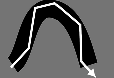
Why should refraction be related to the speed of light? The mechanical model shown in the figure may help to make this more plausible. Suppose medium 2 is thick, sticky mud, which slows down the car. The car's right wheel hits the mud first, causing the right side of the car to slow down. This will cause the car to turn to the right until is moves far enough forward for the left wheel to cross into the mud. After that, the two sides of the car will once again be moving at the same speed, and the car will go straight.
Of course, light isn't a car. Why should a beam of light have anything resembling a “left wheel” and “right wheel?” After all, the mechanical model would predict that a motorcycle would go straight, and a motorcycle seems like a better approximation to a ray of light than a car. The whole thing is just a model, not a description of physical reality.
A Derivation of Snell's law
However intuitively appealing the mechanical model may be, light is a wave, and we should be using wave models to describe refraction. In fact Snell's law can be derived quite simply from wave concepts. Figure \(\PageIndex{9}\) shows the refraction of a water wave. The water in the upper left part of the tank is shallower, so the speed of the waves is slower there, and their wavelengths is shorter. The reflected part of the wave is also very faintly visible.
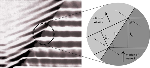
In the close-up view on the right, the dashed lines are normals to the interface. The two marked angles on the right side are both equal to \(\theta_1\), and the two on the left to \(\theta_2\).
Trigonometry gives
\[\begin{align*} \sin \theta_1 &= \lambda_1/h \text{and} \\ \sin \theta_2 &= \lambda_2/h . \end{align*}\]
Eliminating \(h\) by dividing the equations, we find
\[ \frac{\sin\theta_1}{\sin\theta_2}=\frac{\lambda_1}{\lambda_2} . \]
The frequencies of the two waves must be equal or else they would get out of step, so by \(v=f\lambda \) we know that their wavelengths are proportional to their velocities. Combining \(\lambda\propto v\) with \(v\propto 1/n\) gives \(\lambda\propto 1/n\), so we find
\[ \frac{\sin\theta_1}{\sin\theta_2}=\frac{n_2}{n_1} , \]
which is one form of Snell's law.
Ocean waves are formed by winds, typically on the open sea, and the wavefronts are perpendicular to the direction of the wind that formed them. At the beach, however, you have undoubtedly observed that waves tend come in with their wavefronts very nearly (but not exactly) parallel to the shoreline. This is because the speed of water waves in shallow water depends on depth: the shallower the water, the slower the wave. Although the change from the fast-wave region to the slow-wave region is gradual rather than abrupt, there is still refraction, and the wave motion is nearly perpendicular to the normal in the slow region.
Color and Refraction
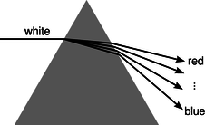
In general, the speed of light in a medium depends both on the medium and on the wavelength of the light. Another way of saying it is that a medium's index of refraction varies with wavelength. This is why a prism can be used to split up a beam of white light into a rainbow. Each wavelength of light is refracted through a different angle.
How much light is reflected, and how much is transmitted?
In section 6.2 we developed an equation for the percentage of the wave energy that is transmitted and the percentage reflected at a boundary between media. This was only done in the case of waves in one dimension, however, and rather than discuss the full three dimensional generalization it will be more useful to go into some qualitative observations about what happens. First, reflection happens only at the interface between two media, and two media with the same index of refraction act as if they were a single medium. Thus, at the interface between media with the same index of refraction, there is no reflection, and the ray keeps going straight. Continuing this line of thought, it is not surprising that we observe very little reflection at an interface between media with similar indices of refraction.
The next thing to note is that it is possible to have situations where no possible angle for the refracted ray can satisfy Snell's law. Solving Snell's law for \(\theta_2\), we find
\[ \theta_2 = \sin^{-1}\left(\frac{n_1}{n_2}\sin\theta_1\right) , \]
and if \(n_1\) is greater than \(n_2\), then there will be large values of \(\theta_1\) for which the quantity \((n_1/n_2)\sin\theta \) is greater than one, meaning that your calculator will flash an error message at you when you try to take the inverse sine. What can happen physically in such a situation? The answer is that all the light is reflected, so there is no refracted ray. This phenomenon is known as total internal reflection, and is used in the fiber-optic cables that nowadays carry almost all long-distance telephone calls.
The electrical signals from your phone travel to a switching center, where they are converted from electricity into light. From there, the light is sent across the country in a thin transparent fiber. The light is aimed straight into the end of the fiber, and as long as the fiber never goes through any turns that are too sharp, the light will always encounter the edge of the fiber at an angle sufficiently oblique to give total internal reflection. If the fiber-optic cable is thick enough, one can see an image at one end of whatever the other end is pointed at.
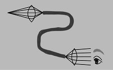
Alternatively, a bundle of cables can be used, since a single thick cable is too hard to bend. This technique for seeing around corners is useful for making surgery less traumatic. Instead of cutting a person wide open, a surgeon can make a small “keyhole” incision and insert a bundle of fiber-optic cable (known as an endoscope) into the body.
Since rays at sufficiently large angles with respect to the normal may be completely reflected, it is not surprising that the relative amount of reflection changes depending on the angle of incidence, and is greatest for large angles of incidence.
Discussion Questions
◊ What index of refraction should a fish have in order to be invisible to other fish?
◊ Does a surgeon using an endoscope need a source of light inside the body cavity? If so, how could this be done without inserting a light bulb through the incision?
◊ A denser sample of a gas has a higher index of refraction than a less dense sample (i.e., a sample under lower pressure), but why would it not make sense for the index of refraction of a gas to be proportional to density?
◊ The earth's atmosphere gets thinner and thinner as you go higher in altitude. If a ray of light comes from a star that is below the zenith, what will happen to it as it comes into the earth's atmosphere?
◊ Does total internal reflection occur when light in a denser medium encounters a less dense medium, or the other way around? Or can it occur in either case?
12.4.2 Lenses
Figures n/1 and n/2 show examples of lenses forming images. There is essentially nothing for you to learn about imaging with lenses that is truly new. You already know how to construct and use ray diagrams, and you know about real and virtual images. The concept of the focal length of a lens is the same as for a curved mirror. The equations for locating images and determining magnifications are of the same form. It's really just a question of flexing your mental muscles on a few examples. The following self-checks and discussion questions will get you started.
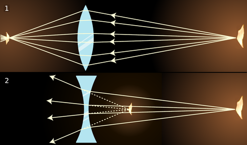
- In figures Figure \(\PageIndex{13; part 1}\) and Figure \(\PageIndex{13; part 2}\), classify the images as real or virtual.
- Glass has an index of refraction that is greater than that of air. Consider the topmost ray in Figure \(\PageIndex{13; part 1}\). Explain why the ray makes a slight left turn upon entering the lens, and another left turn when it exits.
- If the flame in Figure \(\PageIndex{13; part 2}\) were moved closer to the lens, what would happen to the location of the image?
- Answer
-
(answer in the back of the PDF version of the book)
Discussion Questions
◊ In figures n/1 and n/2, the front and back surfaces are parallel to each other at the center of the lens. What will happen to a ray that enters near the center, but not necessarily along the axis of the lens? Draw a BIG ray diagram, and show a ray that comes from off axis.
In discussion questions B-F, don't draw ultra-detailed ray diagrams as in A.
◊ Suppose you wanted to change the setup in figure n/1 so that the location of the actual flame in the figure would instead be occupied by an image of a flame. Where would you have to move the candle to achieve this? What about in n/2?
◊ There are three qualitatively different types of image formation that can occur with lenses, of which figures n/1 and n/2 exhaust only two. Figure out what the third possibility is. Which of the three possibilities can result in a magnification greater than one? Cf. problem 10, p. 797.
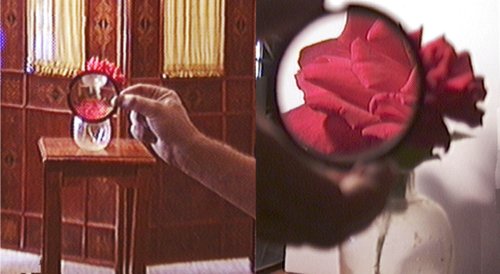
◊ Classify the examples shown in figure o according to the types of images delineated in discussion question C.
◊ In figures n/1 and n/2, the only rays drawn were those that happened to enter the lenses. Discuss this in relation to figure o.
◊ In the right-hand side of figure o, the image viewed through the lens is in focus, but the side of the rose that sticks out from behind the lens is not. Why?
The Lensmaker's Equation

The focal length of a spherical mirror is simply \(r/2\), but we cannot expect the focal length of a lens to be given by pure geometry, since it also depends on the index of refraction of the lens. Suppose we have a lens whose front and back surfaces are both spherical. (This is no great loss of generality, since any surface with a sufficiently shallow curvature can be approximated with a sphere.) Then if the lens is immersed in a medium with an index of refraction of 1, its focal length is given approximately by
where \(n\) is the index of refraction and \(r_1\) and \(r_2\) are the radii of curvature of the two surfaces of the lens. Equation \ref{LM} is known as the lensmaker's equation. In my opinion it is not particularly worthy of memorization. The positive sign is used when both surfaces are curved outward or both are curved inward; otherwise a negative sign applies. The proof of this equation is left as an exercise to those readers who are sufficiently brave and motivated.
12.4.3 Dispersion
For most materials, we observe that the index of refraction depends slightly on wavelength, being highest at the blue end of the visible spectrum and lowest at the red. For example, white light disperses into a rainbow when it passes through a prism, q.
Even when the waves involved aren't light waves, and even when refraction isn't of interest, the dependence of wave speed on wavelength is referred to as dispersion. Dispersion inside spherical raindrops is responsible for the creation of rainbows in the sky, and in an optical instrument such as the eye or a camera it is responsible for a type of aberration called chromatic aberration (subsection 12.3.3 and problem 28). As we'll see in subsection 13.3.2, dispersion causes a wave that is not a pure sine wave to have its shape distorted as it travels, and also causes the speed at which energy and information are transported by the wave to be different from what one might expect from a naive calculation. The microscopic reasons for dispersion of light in matter are discussed in optional subsection 12.4.6.
The principle of least time for refraction
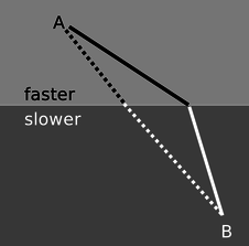
We have seen previously how the rules governing straight-line motion of light and reflection of light can be derived from the principle of least time. What about refraction? In the figure, it is indeed plausible that the bending of the ray serves to minimize the time required to get from a point A to point B. If the ray followed the unbent path shown with a dashed line, it would have to travel a longer distance in the medium in which its speed is slower. By bending the correct amount, it can reduce the distance it has to cover in the slower medium without going too far out of its way. It is true that Snell's law gives exactly the set of angles that minimizes the time required for light to get from one point to another. The proof of this fact is left as an exercise (problem 38, p. 802).
Microscopic description of refraction
Given that the speed of light is different in different media, we've seen two different explanations (on p. 774 and in subsection 12.4.5 above) of why refraction must occur. What we haven't yet explained is why the speed of light does depend on the medium.
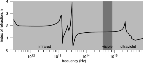
A good clue as to what's going on comes from the figure s. The relatively minor variation of the index of refraction within the visible spectrum was misleading. At certain specific frequencies, \(n\) exhibits wild swings in the positive and negative directions. After each such swing, we reach a new, lower plateau on the graph. These frequencies are resonances. For example, the visible part of the spectrum lies on the left-hand tail of a resonance at about \(2\times10^{15}\ \text{Hz}\), corresponding to the ultraviolet part of the spectrum. This resonance arises from the vibration of the electrons, which are bound to the nuclei as if by little springs. Because this resonance is narrow, the effect on visible-light frequencies is relatively small, but it is stronger at the blue end of the spectrum than at the red end. Near each resonance, not only does the index of refraction fluctuate wildly, but the glass becomes nearly opaque; this is because the vibration becomes very strong, causing energy to be dissipated as heat. The “staircase” effect is the same one visible in any resonance, e.g., figure k on p. 180: oscillators have a finite response for \(f \ll f_0\), but the response approaches zero for \(f \gg f_0\).
So far, we have a qualitative explanation of the frequency-variation of the loosely defined “strength” of the glass's effect on a light wave, but we haven't explained why the effect is observed as a change in speed, or why each resonance is an up-down swing rather than a single positive peak. To understand these effects in more detail, we need to consider the phase response of the oscillator. As shown in the bottom panel of figure j on p. 181, the phase response reverses itself as we pass through a resonance.
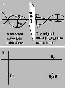
Suppose that a plane wave is normally incident on the left side of a thin sheet of glass, t/1, at \(f \ll f_0\). The light wave observed on the right side consists of a superposition of the incident wave consisting of \(\mathbf{E}_0\) and \(\mathbf{B}_0\) with a secondary wave \(\mathbf{E}^*\) and \(\mathbf{B}^*\) generated by the oscillating charges in the glass. Since the frequency is far below resonance, the response \(q\mathbf{x}\) of a vibrating charge \(q\) is in phase with the driving force \(\mathbf{E}_0\). The current is the derivative of this quantity, and therefore 90 degrees ahead of it in phase. The magnetic field generated by a sheet of current has been analyzed in subsection 11.2.1, and the result, shown in figure e on p. 664, is just what we would expect from the right-hand rule. We find, t/1, that the secondary wave is 90 degrees ahead of the incident one in phase. The incident wave still exists on the right side of the sheet, but it is superposed with the secondary one. Their addition is shown in t/2 using the complex number representation introduced in subsection 10.5.7. The superposition of the two fields lags behind the incident wave, which is the effect we would expect if the wave had traveled more slowly through the glass.
In the case \(f \gg 0\), the same analysis applies except that the phase of the secondary wave is reversed. The transmitted wave is advanced rather than retarded in phase. This explains the dip observed in figure s after each spike.
All of this is in accord with our understanding of relativity, ch. 7, in which we saw that the universal speed \(c\) was to be understood fundamentally as a conversion factor between the units used to measure time and space --- not as the speed of light. Since \(c\) isn't defined as the speed of light, it's of no fundamental importance whether light has a different speed in matter than it does in vacuum. In fact, the picture we've built up here is one in which all of our electromagnetic waves travel at \(c\); propagation at some other speed is only what appears to happen because of the superposition of the \((\mathbf{E}_0,\mathbf{B}_0)\) and \((\mathbf{E}^*,\mathbf{B}^*)\) waves, both of which move at \(c\).
But it is worrisome that at the frequencies where \(n\lt1\), the speed of the wave is greater than \(c\). According to special relativity, information is never supposed to be transmitted at speeds greater than \(c\), since this would produce situations in which a signal could be received before it was transmitted! This difficulty is resolved in subsection 13.3.2, where we show that there are two different velocities that can be defined for a wave in a dispersive medium, the phase velocity and the group velocity. The group velocity is the velocity at which information is transmitted, and it is always less than \(c\).
Benjamin Crowell (Fullerton College). Conceptual Physics is copyrighted with a CC-BY-SA license.