
02. Analysis Tools


- Last updated
- Oct 1, 2024
- Save as PDF

( \newcommand{\kernel}{\mathrm{null}\,}\)
Long, Parallel Wires
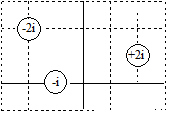
Three long, parallel wires are located as shown. Each grid square has a width a. Find the net magnetic force per unit length on the rightmost wire.
The magnetic force on a current-carrying wire is given by the relation,
→F=∫i(d→l)×→B
However, for this scenario the relationship simplifies. First, the magnetic field from the two source wires is constant along the entire length of the wire of interest. Second, since the wire of interest is straight, d→l is also constant. Therefore, instead of an integral you have:

where L is the total length of the wire of interest.
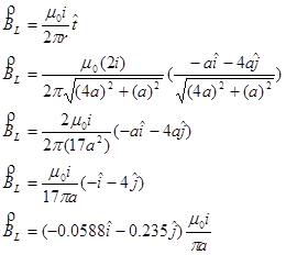
To solve this problem, first find the net magnetic field at the location of the wire of interest, and then perform the cross-product. The magnetic field will be the vector sum of the magnetic field for the leftmost wire (BL) and the magnetic field from the central wire (BC).
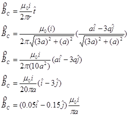
Adding these two contributions together yields
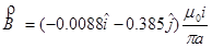
So the magnetic force on the rightmost wire is:
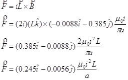
and the force per unit length is
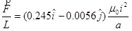
The force is to the right, and slightly downward. Notice that wires carrying currents in opposite directions tend to repel each other, while wires carrying currents in the same direction tend to attract each other.
Curved Wires
The bent wire below carries current i, consists of two straight segments of length 3l and a half-circle of radius L, and lies in a region of uniform magnetic field, B, in the +x-direction. Find the total force acting on the wire.
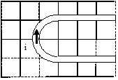
To find the total magnetic force on this bent wire, treat the wire as three separate wires. The force on the two straight sections is zero, because the current in these sections is parallel to the field, resulting in no magnetic force. Therefore, the force on the entire wire is equal to the force on the curved section, which will require setting up and evaluating an integral.
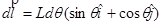
The differential element is located at an angle q, measured clockwise from the -y-axis. At this location, ![]() is directed in the +x-direction and +y-direction. This results in:
is directed in the +x-direction and +y-direction. This results in:
Using this differential element, the force on the 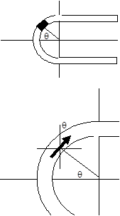
curved secton of wire is given by:
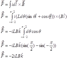
The magnetic force will cause the curved end of the wire to sink into the plane of the page.