
02. Time-Dependent Forces


- Last updated
- Oct 1, 2024
- Save as PDF

( \newcommand{\kernel}{\mathrm{null}\,}\)
Time-Dependent Forces
A 2.0 kg toy rocket is fitted with an engine that provides a thrust roughly modeled by the function F(t) = (60 N/s) t - (15 N/s2) t2, for 0 < t < 4.0 s, and zero thereafter. The rocket is launched directly upward.
Of course, the first step to analyzing any situation involving forces is to construct a free-body diagram. Below is a free-body diagram for the rocket during the time interval 0 < t < 4.0 s.
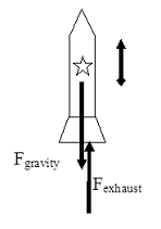
Given that you are not presented with information pertaining to the frictional force acting on the rocket, you must analyze the rocket’s trajectory in a hypothetical, friction-free environment.
From Newton’s second law:
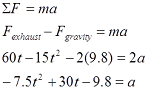
Thus, the acceleration of the rocket is not constant, and the velocity and position of the rocket must be determined by integrating the acceleration.
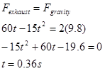
Before we do this, however, note that the acceleration of the rocket is initially directed downward. (At t = 0s, a = -9.8 m/s2.) This is because the supporting force exerted on the rocket by the launch platform has been ignored. This force would hold the rocket in place until the force of the exhaust gases on the rocket is equal to, and then exceeds, the force of gravity on the rocket. In reality, the acceleration of the rocket is zero until Fexhaust = Fgravity. This occurs when:
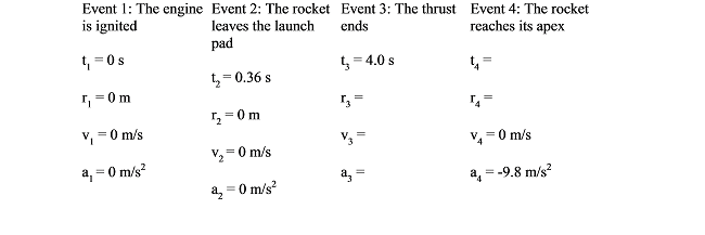
The correct motion information is tabulated below.
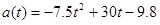
Between event 2 and 3, the rocket's acceleration is given by the function above:
We can integrate the acceleration to determine the velocity,

Since we know v = 0 m/s when t = 0.36 s, we can determine the integration constant:
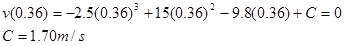
Therefore,
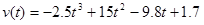
and when the thrust ends, at t3 = 4.0 s, v3 = 42.5 m/s.
To find the position of the rocket when the thrust ends, integrate the velocity function:
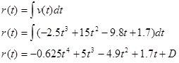
Since we know r = 0 m when t = 0.36 s, we can determine the integration constant:
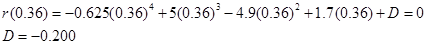
Therefore,

and when the thrust ends, at t3 = 4.0 s, r3= 87.2 m.
Between event 3 and 4 the acceleration is constant, so we can use our constant-acceleration kinematic equations:
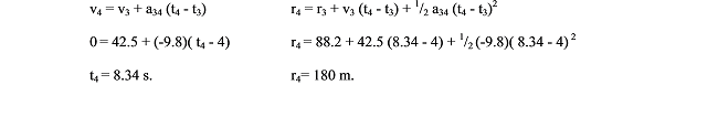
Thus, the rocket would achieve a maximum height of 180 m in a friction-free environment.