
02. Pure Rotation


- Last updated
- Oct 1, 2024
- Save as PDF

( \newcommand{\kernel}{\mathrm{null}\,}\)
Pure Rotation
After the off button is pressed, a ceiling fan takes 22 s to come to rest. During this time, it completes 18 complete revolutions.
To analyze this situation, we should first carefully determine and define the sequence of events that take place. At each of these instants, let's tabulate what we know about the motion. Since we are dealing with pure rotation, the relevant kinematic variables are the angular position, velocity, and acceleration of the fan. Also, let's take the direction that the fan is initially rotating to be the positive direction.

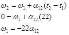
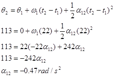
Since no specific information concerning the angular acceleration of the fan is given, let's assume the angular acceleration is constant. (Thus, a1 = a2 = a12.) Since the relationships between angular position, velocity, and acceleration are the same as the relationships between linear position, velocity and acceleration, the kinematic equations for constant linear acceleration must have direct analogies for constant angular acceleration. Thus,
Now substitute this expression into the other equation:
Substitute this result back into the original equation:
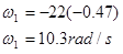
Notice that the sign of the angular acceleration is negative. This indicates that the angular acceleration is in the opposite direction of the angular velocity, as it should be since the fan is slowing down.
Connecting Pure Rotation to Pure Translation
The device at right is used to lift a heavy load. The free rope is attached to a truck which accelerates from rest at a rate of 1.5 m/s2. The inner radius of the pulley is 20 cm and the outer radius is 40 cm. The load must be raised 15 m.
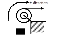
The coordinate system chosen indicates that the block moving upward, the pulley rotating clockwise, and the trunk moving to the right are all positive.
There are three different objects that we should be able to describe kinematically; the truck, the pulley, and the block. Let's tabulate everything we know about each object:
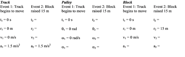
The truck and block exhibit translational motion, so we only have to tabulate linear variables. The pulley spins, so the relevant variables are the angular variables. Notice that just because the block moves 15 m doesn't mean the truck moves 15 m. Also, the acceleration of the block is not equal to the acceleration of the truck. However, these variables are related to each other since both objects are attached to the same pulley.
Also notice that we can't currently solve this problem. Each of the objects has three unknown quantities. However, since the kinematics of the three objects are related, we will be able to solve the problem once we've worked out the exact relationship between each object's kinematics.
Let's start with the acceleration. Assuming the rope from the truck does not slip on the pulley, the point on the pulley in contact with the rope must be acceleration at the same rate as the truck. Notice that this acceleration is tangent to the pulley, and this rope is located 0.4 m from the center of the pulley. Therefore, from
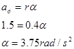
The pulley must have an angular acceleration of 3.75 rad/s2 since it is attached to the truck.
In addition, assuming the rope from the block does not slip on the pulley, the point on the pulley in contact with this rope must be accelerating at:
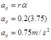
Since the point on the pulley attached to the block is accelerating at 0.75 m/s2, the block itself must be accelerating at 0.75 m/s2. In a nutshell, what we've done is used the acceleration of the truck to find the angular acceleration of the pulley, and then used the angular acceleration of the pulley to find the acceleration of the block. This chain of reasoning is very common.
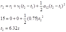
Now that we know the block's acceleration, we can solve the problem. Applying the two kinematic equations to the block yields:
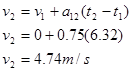
Now that we know the final speed of the block, we can find the final angular speed of the pulley and the final speed of the truck:
Again assuming the rope from the block does not slip on the pulley, the point on the pulley in contact with the rope must be moving at the same rate as the block. Notice that this velocity is tangent to the pulley, and this rope is located 0.2 m from the center of the pulley. Therefore, from
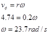
The pulley must have an angular velocity of 23.7 rad/s since it is attached to the block.
In addition, assuming the rope from the truck does not slip on the pulley, the point on the pulley in contact with this rope must be moving at:

The truck is moving at 9.48 m/s when the block reaches 15 m.
We can relate the displacement of the block to the angular displacement of the pulley and the displacement of the truck using

where s is (technically) the arc length over which a rope is wrapped around the pulley and q is the angular displacement of the pulley. Of course, the amount of rope wrapped around a pulley is exactly equal to displacement of the object attached to the rope. Therefore, relating the block to the pulley yields

The pulley must have turned through 75 rad since it is attached to the block.
Relating the pulley to the truck results in:

The truck moved 30 m while the block moved 15 m.
Notice that in all cases, the values of the kinematics variables for the truck are exactly twice the values for the block. This is not a coincidence. Since the truck is attached, all of its kinematic variables will have twice the value. Once you understand why this is the case, you can use this insight to simplify your analysis.