
23.2: Induction in a Moving Conductor


- Last updated
- Mar 28, 2024
- Save as PDF
( \newcommand{\kernel}{\mathrm{null}\,}\)
If we define a loop of wire, there are two ways in which the magnetic flux through that loop can change:
- The magnetic field can change magnitude or direction, as we saw in Example 23.1.1.
- The loop can change size or orientation relative to the magnetic field.
In this section, we examine the latter case, sometimes called “motional emf”, as the induced voltage is the result of motion from the loop in which the voltage is induced.
Motion of a bar on two parallel rails
Consider a U-shaped rail in a uniform magnetic field on top of which a bar can slide with no friction, as illustrated in Figure 23.2.1. The bar of length L moves to the right with a constant speed, v.
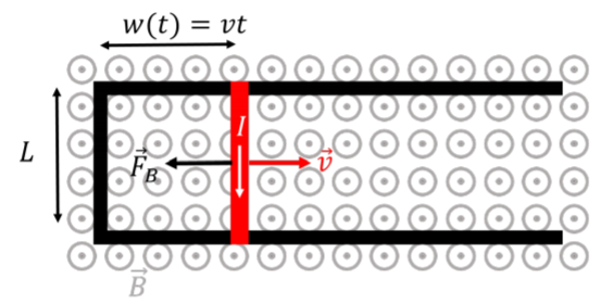
The bar and the rails form a closed loop of area:
A(t)=Lw(t)=Lvt
that increases with time. The magnitude of the flux through the loop will increase with time, resulting in an induced current (clockwise, according to Lenz’s Law). At some time, t, the flux through the loop is given by:
ΦB(t)=→B⋅→A=BA=BLvt
where we chose →A to be parallel to the magnetic field vector.
Since we already used Lenz’s Law to argue that the current must be in the clockwise direction, we can use Faraday’s Law to determine the magnitude of the induced voltage and ignore the negative sign:
ΔV=dΦBdt=ddtBLvt=BLv
Suppose that the rails are superconducting (have no resistance), and that the bar has a resistance, R. The current through the loop is then given by Ohm’s Law:
I=ΔVR=BLvR
As the current moves through the bar, it will heat up the bar by dissipating energy at a rate of:
P=I2R=B2L2v2R
Thus, the bar cannot possibly move at a constant speed by its own, or energy would be produced out of nothing. There must be a force exerted on the bar to keep it moving at constant speed.
Recall that a current-carrying wire in a magnetic field will experience a force from the magnetic field. In this case, the bar of length L, carries current, I, in a magnetic field, →B (perpendicular to the current), so that the force exerted on the bar is given by:
→FB=I→L×→B
and points to the left (right-hand rule). The magnitude of the force is given by:
FB=ILB=B2L2vR
Thus, in order for the bar to move at constant velocity towards the right, a force with the same magnitude must be exerted towards the right. In other words, work must be done to pull the bar to the right, by exerting a force with the magnitude, FB. The rate at which that work must be done is given by:
P=ddtW=ddt→F⋅dx=→F⋅dxdt=→F⋅→v=Fv=B2L2v2R
where we assumed that the bar moves in the positive x direction. This is exactly the rate at which electric energy is dissipated in the bar! In other words, by doing mechanical work on the bar, we can create an induced current that will dissipate that energy at the same rate at which we do work. We can convert mechanical work into electrical energy!
Finally, also note that this situation is closely related to the Hall effect, which is simply a different way to think about this problem. Consider the electrons that are in the bar, as the bar moves at constant speed to the right through the magnetic field (ignore the existence of the U-shaped rail). The electrons will experience a magnetic force that is upwards (consistent with the direction of the induced current discussed above). Eventually, electrons accumulate at the top of the bar, and start preventing more electrons from accumulating there, by producing an electric field, →E, in the bar. The equilibrium condition is that the magnetic force and the electric force have the same magnitude (and opposite directions):
qvB=qEE=vB
The (Hall) potential difference, across the bar of length, L, with an electric field, E, is given by:
ΔVHall=EL=vBL
where we assumed that the electric field is uniform in the bar. This potential difference is identical to the one that we calculated from Faraday’s Law. Viewing this example as a different manifestation of the Hall effect provides some insight into what is actually happening at the microscopic level when a current is induced.
The Generator
An electrical generator is used to create an alternating induced voltage/current, by rotating a coil inside of a constant and uniform magnetic field. In this case, the current is induced because the angle between the magnetic field and the surface element vector d→A changes with time.
Consider a single loop of wire with area A, that can rotate in a uniform and constant magnetic field, →B, as illustrated in Figure 23.2.2.
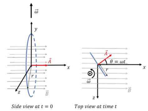
Referring to the coordinate system that is illustrated in Figure 23.2.2, the loop has a constant angular velocity, →ω, in the positive y direction and rotates about the y axis (with the origin at the center of the coil). At time t=0 (left panel), the loop lies in the yz plane, and we choose the vector, →A, (used to calculate the flux) to be in the positive x direction at time t=0. As the coil rotates, so will the vector →A, which is easier to visualize than the coil. At some time t, the vector →A will make an angle θ=ωt with the x axis (right panel). The magnetic field is constant and in the positive x direction, →B=Bˆx. That is, the angle between the vector →A and the magnetic field, →B, will be given by θ=ωt.
At some time, t, the vector, →A, is given by:
→A(t)=A(cosθˆx−sinθˆz)=A(cos(ωt)ˆx−sin(ωt)ˆz)
We can calculate the flux of the magnetic field through the loop at some time t:
ΦB(t)=→B⋅→A=(Bˆx)⋅(cos(ωt)ˆx−sin(ωt)ˆz)=ABcos(ωt)
where we did not use the integral for the flux, since the magnetic field is constant over the area of the loop. The induced voltage is given by Faraday’s Law:
ΔV=−dΦBdt=−ddtABcos(ωt)=ABωsin(ωt)
If the generator includes N loops in a coil, then the induced voltage is given by:
ΔV=NABωsin(ωt)
As you can see, the voltage oscillates with time, between ±NABω, corresponding to alternating voltage. Furthermore, since the sign of ΔV changes with time (due to the sine function), the relative orientation between →A, and the magnetic dipole moment of the induced current, also changes with time, indicating that the induced current in the coil changes direction every half-turn (alternating current).
The generators that produce the alternating voltages that we find in our outlets work on the same principle. For example, in a hydro-electric dam, the water pressure from the height of the dam is used to force water through a turbine (essentially a propeller) that rotates a set of coils inside of a strong permanent magnet. Various controls allow the rotational frequency of the turbine to be adjusted in order to produce alternating current of the desired frequency (50Hz in most of the world, 60Hz in North America and a few other countries).
Since the generator produces current that can dissipate electrical energy, one must have to do work in order to keep the coil in the generator rotating. As the coil rotates, a current is induced in the coil. A current in a circular loop that is immersed in a magnetic field will experience a torque, →τ, given by:
→τ=→μ×→B
where →μ is the magnetic dipole moment of the coil with induced current, I. If the current from the coil dissipates its energy in a system with resistance, R, then the current in the coil is given by Ohm’s Law:
I=ΔVR=NABωsin(ωt)R
The magnetic moment, →μ, for the current in the coil is given by:
→μ=I→A=NABωsin(ωt)R(A(cos(ωt)ˆx−sin(ωt)ˆz))=NA2Bωsin(ωt)R(cos(ωt)ˆx−sin(ωt)ˆz)
The torque exerted by the magnetic field on the coil with the induced current is thus given by:
→τ=→μ×→B=(NA2Bωsin(ωt)R(cos(ωt)ˆx−sin(ωt)ˆz))×(Bˆx)=NA2B2ωsin(ωt)R(cosω(t)(ˆx׈x)−sin(ωt)(ˆz׈x))=−NA2B2ωsin2(ωt)Rˆy
Note that the torque exerted on the loop, is always in the negative y direction, as every term in the torque is either strictly positive (N,R) or squared (sin2(ωt)). The torque exerted by the magnetic field on the coil is thus always in the opposite direction of rotation (recall that the coil has an angular velocity in the positive y direction). This is sometimes called “counter torque”. If we want the coil to maintain a constant angular velocity, then we must exert a torque in the positive y direction to counter the torque from the magnetic field. Note that the torque that we must exert to keep the coil rotating with constant angular velocity is not constant in time (but always in the same direction).
You can easily verify that the work that you must do by exerting the torque is the same as the electrical power dissipated by the current in the resistor, R. The generator is thus a device to convert mechanical work into electrical energy (with AC current, in particular).