
23.1: Faraday’s Law


- Last updated
- Mar 28, 2024
- Save as PDF
( \newcommand{\kernel}{\mathrm{null}\,}\)
In the previous chapter, we described how an electric current produces a magnetic field. In this chapter, we describe how an electric current can be produced (or rather, “induced”) by a magnetic field. The most important aspect of electromagnetic induction is that it always involves quantities that change with time. In past chapters, we have only dealt with static electric and magnetic fields, static charges (for electric fields), and static currents (for magnetic fields).
Faraday’s Law connects the flux of a time-varying magnetic field to an induced voltage (rather than a current). For historical reasons, the induced voltage is also called an induced “electromotive force” (emf), even if it is a voltage and not a force. Faraday’s Law is as follows:
ΔV=−dΦBdt
where ΔV is the induced voltage, and ΦB is the flux of the magnetic field through an open surface, defined in the same way as the flux of the electric field (Section 17.1):
ΦB=∫S→B⋅d→A
If the magnetic field has a constant magnitude over the surface, S, and always makes the same angle with the surface, then the flux can be written as:
ΦB=→B⋅→A
where the magnitude of the vector →A is equal to the area of the surface, and the vector →A is normal to the surface.
The surface, S, is defined by a closed path. The induced voltage can be thought of as an ideal battery placed in the closed path that defines the surface (right-hand panel of Figure 23.1.1). The minus sign indicates the direction of the current associated with the induced voltage. It is important to note that an induced voltage only exists if the flux of the magnetic field changes (since the induced voltage is given by the time-derivative of the flux). Remember, induction is all about time-varying fields! This is better illustrated with an example.
Consider a loop of wire that is immersed in a uniform magnetic field, →B, that is perpendicular to the plane of the loop, as illustrated in Figure 23.1.1. As time goes by, the magnetic field increases in strength, as shown in going from the left panel to the right panel. The flux of the magnetic field through the loop increases in magnitude, and a voltage is thus induced across the wire (illustrated by the ideal battery on the loop in the right panel), leading to an induced current, I.
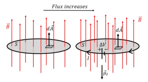
When calculating the flux of the magnetic field, we have to choose the surface element vector, d→A, to be perpendicular to the surface over which we calculate the flux. There are two choices1 (upwards or downwards, referring to Figure 23.1.1); we chose to define d→A to point upwards. Thus, the magnetic flux is positive in both panels, and increases with time. The derivative, d→B/dt, is thus positive, and the right-hand side of Faraday’s equation is negative because of the negative sign in front. Had we chosen to define d→A to point downwards, the right-hand side of Faraday’s Law would be negative.
We can describe the direction of the induced current, I, in terms of its magnetic dipole moment (Section 21.4), →μI, also shown in Figure 23.1.1. The overall sign on the right-hand side of Faraday’s Law is determined by our (arbitrary) choice of the direction d→A. With this choice, we found that the right-hand side of Faraday’s Law is negative:
ΔV=−dΦBdt=a negative number
The overall sign of ΔV indicates whether the magnetic moment of the induced current is parallel (ΔV positive) or anti-parallel (ΔV negative) to d→A. This allows us to determine the direction of the induced current, and thus the direction of the ideal battery that represents the induced voltage. In general, when possible, it is common to choose the direction of d→A to be parallel to the magnetic field vector, so that the flux is positive (although this does not guarantee that its derivative is positive).
Lenz’ Law
The minus sign in Faraday’s Law is sometimes called “Lenz’s Law”, and ultimately comes from the conservation of energy. In Figure 23.1.1 above, we found that as the magnetic flux increases through the loop, a current is induced. That induced current will also produce a magnetic field (in the direction of its magnetic dipole moment vector, →μI).
Lenz’s Law states that the “induced current will always be such that the magnetic field that it produces counteracts the changing magnetic field that induced the current”. In Figure 23.1.1, the magnetic field points in the upwards direction, and increases in magnitude with time. The induced current produces a magnetic field that points downwards to counteract the changing magnetic field, and preserve a constant flux through the loop. If this were not the case, the induced current would be in the opposite direction, contributing to the increasing magnetic flux through the loop, inducing more current, producing more flux, inducing more current, etc. Clearly, this would lead to an infinite current and solve the world’s energy crisis. Unfortunately, conservation of energy (expressed here as Lenz’s Law) prevents this from happening.
You can use Lenz’s Law to determine the direction of induced currents. In general:
- If the magnitude of the magnetic flux is increasing in the loop, then the induced current produces a magnetic field that is in the opposite direction from the original magnetic field.
- If the magnitude of the magnetic flux is decreasing in the loop, then the induced current produces a magnetic field that is in the same direction as the original magnetic field.
The negative sign in Faraday’s Law is not arbitrary (as we saw above, it gives the correct direction for the magnetic moment of the induced current, given our arbitrary choice of direction for d→A). In practice, one can often use Lenz’s Law to determine the direction of the induced current (so that it counteracts the changing flux), and Faraday’s Law to determine the magnitude of the induced voltage.
A loop of wire is immersed in a constant and uniform magnetic field out of the page, perpendicular to the plane of the loop, as shown in Figure 23.1.2. If the radius of the loop increases with time, in which direction will be the current induced in the loop?
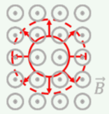
- Since the magnetic field is constant, there is no induced current.
- Clockwise.
- Counter-clockwise.
- Answer
-
A loop of wire is immersed in a constant and uniform magnetic field out of the page, perpendicular to the plane of the loop, as shown in Figure 23.1.3. If the loop is pulled out of the region of magnetic field, as shown, in which direction is the induced current in the loop?
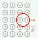
- Since the magnetic field is constant, there is no induced current.
- Clockwise.
- Counter-clockwise.
- Answer
A uniform time-varying magnetic field is given by:
→B(t)=B0(1+at)ˆz
where B0 and a are positive constants. A coil, made of N circular loops of radius, r, lies in the x−y plane. If the coil has a total resistance, R, what is the magnitude and direction of the current induced in the coil?
Solution
The coil is made of N loops of wire. Each loop of wire can be treated independently, and each will have its own induced voltage across it. Since each loop is the same, they will all have the same induced voltage, and the total voltage induced across the coil, ΔV, will be given by:
ΔV=−NdΦBdt
where ΦB is the flux through any one of the loops. That is, each loop is similar to an ideal battery, and the coil is similar to placing all of these batteries in series, so that the voltages from each battery sum together.
The coil lies the x−y plane, perpendicular to the increasing magnetic field, similar to the situation depicted in Figure 23.1.1. Since the magnetic field is uniform over the surface of the coil, we do not need an integral to determine the flux. We define the area vector, →A, to be in the positive z direction (parallel to the magnetic field):
→A=Aˆz=πr2ˆz
The flux through one circular loop of radius, r, is given by:
ΦB(t)=→B⋅→A=(B0(1+at)ˆz)⋅(πr2ˆz)=B0(1+at)(πr2)
We can apply Faraday’s Law to determine the induced voltage:
ΔV=−NdΦBdt=−NddtB0(1+at)(πr2)=−NB0aπr2
Since the induced voltage is negative, the magnetic moment of the induced current points in the negative z direction (opposite to our choice of direction for →A). This is consistent with Len’z Law, since the magnetic field increases in the positive z direction, the induced current will produce a magnetic field in the negative z direction to counteract the changing flux. The magnitude of the induced current is given by Ohm’s Law:
I=ΔVR=NB0aπr2R
Discussion
In this example, we determined the induced voltage and current in a coil made of N identical loops. We argued that one can sum the induced voltages from the N loops, as these can be thought of as ideal batteries in series. We found that the direction of the induced current as obtained from Faraday’s Law was consistent with the expectation from Lenz’s Law.
Footnotes
1. Recall that this ambiguity is resolved when using Gauss’ Law by always choosing d→A to point “outwards”, which only makes sense when the surface is closed. With an open surface, there is no inside or outside, and we are left with the ambiguity.