
24.3: Lenses
- Page ID
- 15717
\( \newcommand{\vecs}[1]{\overset { \scriptstyle \rightharpoonup} {\mathbf{#1}} } \)
\( \newcommand{\vecd}[1]{\overset{-\!-\!\rightharpoonup}{\vphantom{a}\smash {#1}}} \)
\( \newcommand{\dsum}{\displaystyle\sum\limits} \)
\( \newcommand{\dint}{\displaystyle\int\limits} \)
\( \newcommand{\dlim}{\displaystyle\lim\limits} \)
\( \newcommand{\id}{\mathrm{id}}\) \( \newcommand{\Span}{\mathrm{span}}\)
( \newcommand{\kernel}{\mathrm{null}\,}\) \( \newcommand{\range}{\mathrm{range}\,}\)
\( \newcommand{\RealPart}{\mathrm{Re}}\) \( \newcommand{\ImaginaryPart}{\mathrm{Im}}\)
\( \newcommand{\Argument}{\mathrm{Arg}}\) \( \newcommand{\norm}[1]{\| #1 \|}\)
\( \newcommand{\inner}[2]{\langle #1, #2 \rangle}\)
\( \newcommand{\Span}{\mathrm{span}}\)
\( \newcommand{\id}{\mathrm{id}}\)
\( \newcommand{\Span}{\mathrm{span}}\)
\( \newcommand{\kernel}{\mathrm{null}\,}\)
\( \newcommand{\range}{\mathrm{range}\,}\)
\( \newcommand{\RealPart}{\mathrm{Re}}\)
\( \newcommand{\ImaginaryPart}{\mathrm{Im}}\)
\( \newcommand{\Argument}{\mathrm{Arg}}\)
\( \newcommand{\norm}[1]{\| #1 \|}\)
\( \newcommand{\inner}[2]{\langle #1, #2 \rangle}\)
\( \newcommand{\Span}{\mathrm{span}}\) \( \newcommand{\AA}{\unicode[.8,0]{x212B}}\)
\( \newcommand{\vectorA}[1]{\vec{#1}} % arrow\)
\( \newcommand{\vectorAt}[1]{\vec{\text{#1}}} % arrow\)
\( \newcommand{\vectorB}[1]{\overset { \scriptstyle \rightharpoonup} {\mathbf{#1}} } \)
\( \newcommand{\vectorC}[1]{\textbf{#1}} \)
\( \newcommand{\vectorD}[1]{\overrightarrow{#1}} \)
\( \newcommand{\vectorDt}[1]{\overrightarrow{\text{#1}}} \)
\( \newcommand{\vectE}[1]{\overset{-\!-\!\rightharpoonup}{\vphantom{a}\smash{\mathbf {#1}}}} \)
\( \newcommand{\vecs}[1]{\overset { \scriptstyle \rightharpoonup} {\mathbf{#1}} } \)
\(\newcommand{\longvect}{\overrightarrow}\)
\( \newcommand{\vecd}[1]{\overset{-\!-\!\rightharpoonup}{\vphantom{a}\smash {#1}}} \)
\(\newcommand{\avec}{\mathbf a}\) \(\newcommand{\bvec}{\mathbf b}\) \(\newcommand{\cvec}{\mathbf c}\) \(\newcommand{\dvec}{\mathbf d}\) \(\newcommand{\dtil}{\widetilde{\mathbf d}}\) \(\newcommand{\evec}{\mathbf e}\) \(\newcommand{\fvec}{\mathbf f}\) \(\newcommand{\nvec}{\mathbf n}\) \(\newcommand{\pvec}{\mathbf p}\) \(\newcommand{\qvec}{\mathbf q}\) \(\newcommand{\svec}{\mathbf s}\) \(\newcommand{\tvec}{\mathbf t}\) \(\newcommand{\uvec}{\mathbf u}\) \(\newcommand{\vvec}{\mathbf v}\) \(\newcommand{\wvec}{\mathbf w}\) \(\newcommand{\xvec}{\mathbf x}\) \(\newcommand{\yvec}{\mathbf y}\) \(\newcommand{\zvec}{\mathbf z}\) \(\newcommand{\rvec}{\mathbf r}\) \(\newcommand{\mvec}{\mathbf m}\) \(\newcommand{\zerovec}{\mathbf 0}\) \(\newcommand{\onevec}{\mathbf 1}\) \(\newcommand{\real}{\mathbb R}\) \(\newcommand{\twovec}[2]{\left[\begin{array}{r}#1 \\ #2 \end{array}\right]}\) \(\newcommand{\ctwovec}[2]{\left[\begin{array}{c}#1 \\ #2 \end{array}\right]}\) \(\newcommand{\threevec}[3]{\left[\begin{array}{r}#1 \\ #2 \\ #3 \end{array}\right]}\) \(\newcommand{\cthreevec}[3]{\left[\begin{array}{c}#1 \\ #2 \\ #3 \end{array}\right]}\) \(\newcommand{\fourvec}[4]{\left[\begin{array}{r}#1 \\ #2 \\ #3 \\ #4 \end{array}\right]}\) \(\newcommand{\cfourvec}[4]{\left[\begin{array}{c}#1 \\ #2 \\ #3 \\ #4 \end{array}\right]}\) \(\newcommand{\fivevec}[5]{\left[\begin{array}{r}#1 \\ #2 \\ #3 \\ #4 \\ #5 \\ \end{array}\right]}\) \(\newcommand{\cfivevec}[5]{\left[\begin{array}{c}#1 \\ #2 \\ #3 \\ #4 \\ #5 \\ \end{array}\right]}\) \(\newcommand{\mattwo}[4]{\left[\begin{array}{rr}#1 \amp #2 \\ #3 \amp #4 \\ \end{array}\right]}\) \(\newcommand{\laspan}[1]{\text{Span}\{#1\}}\) \(\newcommand{\bcal}{\cal B}\) \(\newcommand{\ccal}{\cal C}\) \(\newcommand{\scal}{\cal S}\) \(\newcommand{\wcal}{\cal W}\) \(\newcommand{\ecal}{\cal E}\) \(\newcommand{\coords}[2]{\left\{#1\right\}_{#2}}\) \(\newcommand{\gray}[1]{\color{gray}{#1}}\) \(\newcommand{\lgray}[1]{\color{lightgray}{#1}}\) \(\newcommand{\rank}{\operatorname{rank}}\) \(\newcommand{\row}{\text{Row}}\) \(\newcommand{\col}{\text{Col}}\) \(\renewcommand{\row}{\text{Row}}\) \(\newcommand{\nul}{\text{Nul}}\) \(\newcommand{\var}{\text{Var}}\) \(\newcommand{\corr}{\text{corr}}\) \(\newcommand{\len}[1]{\left|#1\right|}\) \(\newcommand{\bbar}{\overline{\bvec}}\) \(\newcommand{\bhat}{\widehat{\bvec}}\) \(\newcommand{\bperp}{\bvec^\perp}\) \(\newcommand{\xhat}{\widehat{\xvec}}\) \(\newcommand{\vhat}{\widehat{\vvec}}\) \(\newcommand{\uhat}{\widehat{\uvec}}\) \(\newcommand{\what}{\widehat{\wvec}}\) \(\newcommand{\Sighat}{\widehat{\Sigma}}\) \(\newcommand{\lt}{<}\) \(\newcommand{\gt}{>}\) \(\newcommand{\amp}{&}\) \(\definecolor{fillinmathshade}{gray}{0.9}\)learning objectives
- Describe properties of a thin lens and the purpose of ray tracing
Thin Lenses and Ray Tracing
Ray tracing is the technique of determining or following (tracing) the paths that light rays take. Experiments, as well as our own experiences, show that when light interacts with objects several times as large as its wavelength, it travels in straight lines and acts like a ray. (A ray is simply a straight line that originates at a point. ) Its wave characteristics are not pronounced in such situations. Since the wavelength of light is less than a micron (a thousandth of a millimeter), it acts like a ray in the many common situations in which it encounters objects larger than a micron, such as lenses.
For rays passing through matter, the law of refraction is used to trace the paths. Here we use ray tracing to help us understand the action of lenses in situations ranging from forming images on film to magnifying small print to correcting nearsightedness. While ray tracing for complicated lenses, such as those found in sophisticated cameras, may require computer techniques, there is a set of simple rules for tracing rays through thin lenses. A thin lens is defined to be one whose thickness allows rays to refract, as illustrated in, but does not allow properties such as dispersion and aberrations. An ideal thin lens has two refracting surfaces but the lens is thin enough toassume that light rays bend only once. Another way of saying this is that the lens thickness is much much smaller than the focal length of the lens. A thin symmetrical lens has two focal points, one on either side and both at the same distance from the lens. (See. ) Another important characteristic of a thin lens is that light rays through its center are deflected by a negligible amount, as seen in the center rays in the first two figures. The treatment of a lens as a thin lens is known as the “thin lens approximation. ”
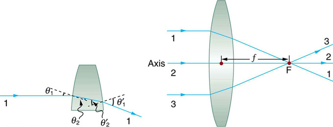
Convex Lens: Rays of light entering a converging lens parallel to its axis converge at its focal point F. (Ray 2 lies on the axis of the lens. ) The distance from the center of the lens to the focal point is the lens’s focal length f. An expanded view of the path taken by ray 1 shows the perpendiculars and the angles of incidence and refraction at both surfaces.

Thin Lens: Thin lenses have the same focal length on either side. (a) Parallel light rays entering a converging lens from the right cross at its focal point on the left. (b) Parallel light rays entering a diverging lens from the right seem to come from the focal point on the right.
Rules for Ray Tracing
Using paper, pencil, and a straight edge, ray tracing can accurately describe the operation of a lens. The rules for ray tracing for thin lenses are based on the illustrations included in this section:
- A ray entering a converging lens parallel to its axis passes through the focal point F of the lens on the other side. ( See rays 1 and 3 in. )
- A ray entering a diverging lens parallel to its axis seems to come from the focal point F. (See rays 1 and 3 in. )
- A ray passing through the center of either a converging or a diverging lens does not change direction. (See ray 2 in and. )
- A ray entering a converging lens through its focal point exits parallel to its axis. (The reverse of rays 1 and 3 in. )
- A ray that enters a diverging lens by heading toward the focal point on the opposite side exits parallel to the axis. (The reverse of rays 1 and 3 in ).
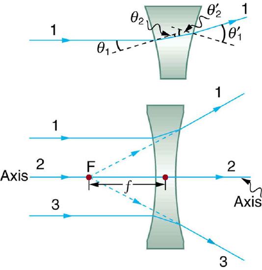
Diverging Lens: Rays of light entering a diverging lens parallel to its axis are diverged, and all appear to originate at its focal point F. The dashed lines are not rays—they indicate the directions from which the rays appear to come. The focal length f of a diverging lens is negative. An expanded view of the path taken by ray 1 shows the perpendiculars and the angles of incidence and refraction at both surfaces.
Ray Diagrams, Concave Lens and Convex Mirror: Shows how to draw the ray diagrams for locating the image produced by a concave lens and a convex mirror.
The Thin Lens Equation and Magnification
The thin lens equation relates the object distance do, image distance di, and focal length f.
learning objectives
- Formulate five basic rules of ray tracing
The Thin Lens Equation and Magnification
Image Formation by Thin Lenses
How does a lens form an image of an object? We can use the technique of ray tracing to illustrate how lenses form images. We can also develop equations to describe the images quantitatively. Recall the five basic rules of ray tracing:
- A ray entering a converging lens parallel to its axis passes through the focal point F of the lens on the other side.
- A ray entering a diverging lens parallel to its axis seems to come from the focal point F.
- A ray passing through the center of either a converging or a diverging lens does not change direction.
- A ray entering a converging lens through its focal point exits parallel to its axis.
- A ray that enters a diverging lens by heading toward the focal point on the opposite side exits parallel to the axis.
Consider an object some distance away from a converging lens, as shown in. To find the location and size of the image formed, we trace the paths of selected light rays originating from one point on the object (in this case the top of the person’s head). The figure shows three rays from the top of the object that can be traced using the five ray tracing rules. Rays leave this point going in many directions, but we concentrate on only a few with paths that are easy to trace. The first ray is one that enters the lens parallel to its axis and passes through the focal point on the other side (rule 1). The second ray passes through the center of the lens without changing direction (rule 3). The third ray passes through the nearer focal point on its way into the lens and leaves the lens parallel to its axis (rule 4). The three rays cross at the same point on the other side of the lens. The image of the top of the person’s head is located at this point. All rays that come from the same point on the top of the person’s head are refracted in such a way as to cross at the point shown. Rays from another point on the object, such as her belt buckle, will also cross at another common point, forming a complete image, as shown. Although three rays are traced in, only two are necessary to locate the image. It is best to trace rays for which there are simple ray tracing rules. Before applying ray tracing to other situations, let us consider the example shown in in more detail.
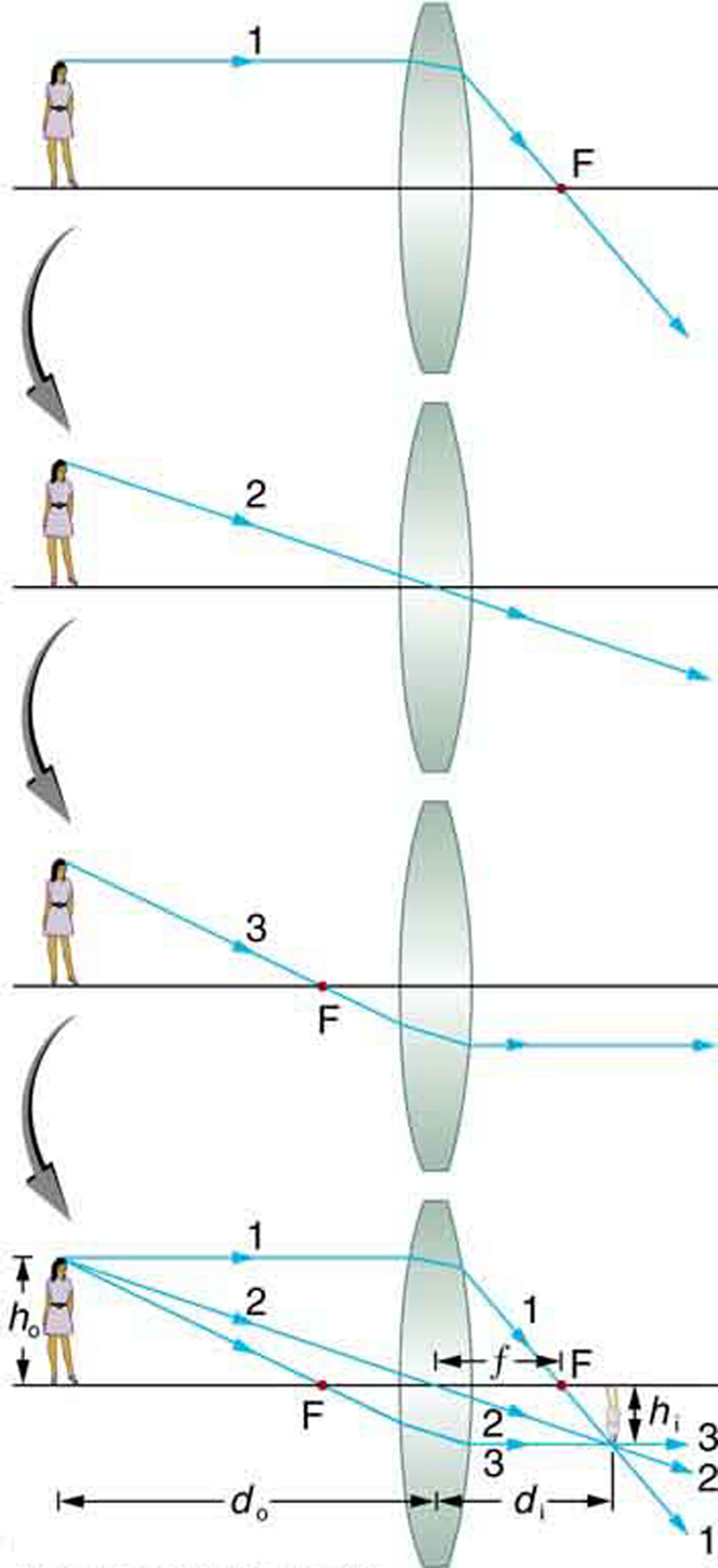
Image Formation with a Thin Lens: Ray tracing is used to locate the image formed by a lens. Rays originating from the same point on the object are traced—the three chosen rays each follow one of the rules for ray tracing, so that their paths are easy to determine. The image is located at the point where the rays cross. In this case, a real image—one that can be projected on a screen—is formed.
Several important distances appear in. We define do as the object distance—the distance of an object from the center of a lens. Image distance diis defined as the distance of the image from the center of a lens. The height of the object and height of the image are given the symbols ho and hi, respectively. Images that appear upright relative to the object have heights that are positive and those that are inverted have negative heights. Using the rules of ray tracing and making a scale drawing with paper and pencil, like that in, we can accurately describe the location and size of an image. But the real benefit of ray tracing is in visualizing how images are formed in a variety of situations. To obtain numerical information, we use a pair of equations that can be derived from a geometric analysis of ray tracing for thin lenses. The thin lens equation is:
\[\dfrac { 1 } { \mathrm { d } _ { o } } + \dfrac { 1 } { \mathrm { d } _ { \mathrm { i } } } = \dfrac { 1 } { \mathrm { f } }\]
We define the ratio of image height to object height (hi/ho) as the magnification m. The magnification is related to do, di, ho, and hi by the following relation:
\[\dfrac { \mathrm { h } _ { \mathrm { i } } } { \mathrm { h } _ { \mathrm { o } } } = - \dfrac { \mathrm { d } _ { \mathrm { i } } } { \mathrm { d } _ { \mathrm { o } } } = \mathrm { m }\]
In many cases both of these equations are referred to together as the thin lens equations. The thin lens equations are broadly applicable to all situations involving thin lenses (and “thin” mirrors).
Thin Lens Equations for a Convex Lens: Shows how to use the thin lens equation to calculate the image distance, image height and image orientation for convex lenses when the object distance is greater the the focal length (f).
Combinations of Lenses
A compound lens is an array of simple lenses with a common axis.
learning objectives
- Calculate focal length for a compound lens from the focal lengths of simple lenses
COMPOUND LENSES
In contrast to a simple lens, which consists of only one optical element, a compound lens is an array of simple lenses (elements) with a common axis. The use of multiple elements allows for the correction of more optical aberrations, such as the chromatic aberration caused by the wavelength-dependent index of refraction in glass, than is possible using a single lens. In many cases these aberrations can be compensated for to a great extent by using a combination of simple lenses with complementary aberrations.
The simplest case is where lenses are placed in contact: if the lenses of focal lengths f1 and f2 are “thin”, the combined focal length f of the lenses is given by
\[\dfrac { 1 } { f } = \dfrac { 1 } { f _ { 1 } } + \dfrac { 1 } { f _ { 2 } }\]
Since 1/f is the power of a lens, it can be seen that the powers of thin lenses in contact are additive.
If two thin lenses are separated in air by some distance d (where d is smaller than the focal length of the first lens), the focal length for the combined system is given by
\[\dfrac { 1 } { f } = \dfrac { 1 } { f _ { 1 } } + \dfrac { 1 } { f _ { 2 } } - \dfrac { d } { f _ { 1 } f _ { 2 } }\]
BACK FOCAL LENGTH
The distance from the second lens to the focal point of the combined lenses is called the back focal length (BFL).
\[\mathrm { BFL } = \dfrac { \mathrm { f } _ { 2 } \left( \mathrm { d } - \mathrm { f } _ { 1 } \right) } { \mathrm { d } - \left( \mathrm { f } _ { 1 } + \mathrm { f } _ { 2 } \right) }\]
As d tends to zero, the value of the BFL tends to the value of f given for thin lenses in contact.
If the separation distance is equal to the sum of the focal lengths (d = f1+f2), the combined focal length and BFL are infinite. This corresponds to a pair of lenses that transform a parallel (collimated) beam into another collimated beam (see ). This type of system is called an afocal system, since it produces no net convergence or divergence of the beam. Two lenses at this separation form the simplest type of optical telescope. Although the system does not alter the divergence of a collimated beam, it does alter the width of the beam. The magnification of such a telescope is given by
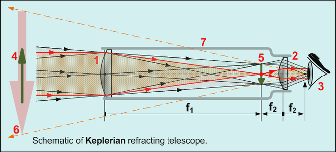
Keplerian Telescope: All refracting telescopes use the same principles. The combination of an objective lens 1 and some type of eyepiece 2 is used to gather more light than the human eye could collect on its own, focus it 5, and present the viewer with a brighter, clearer, and magnified virtual image 6. The magnification can be found by dividing the focal length of the objective lens by the focal length of the eyepiece.
\[\mathrm { M } = - \dfrac { \mathrm { f } _ { 2 } } { \mathrm { f } _ { 1 } }\]
which is the ratio of the input beam width to the output beam width. Note the sign convention: a telescope with two convex lenses (f1 > 0, f2 > 0) produces a negative magnification, indicating an inverted image. A convex plus a concave lens (f1 > 0 >f2) produces a positive magnification and the image is upright.
ACHROMATS
An achromatic lens or achromat is a lens that is designed to limit the effects of chromatic and spherical aberration. Achromatic lenses are corrected to bring two wavelengths (typically red and blue/violet) into focus in the same plane.
The most common type of achromat is the achromatic doublet, which is composed of two individual lenses made from glasses with different amounts of dispersion Typically, one element is a negative (concave) element made out of flint, which has relatively high dispersion, and the other is a positive (convex) element made of crown glass, which has lower dispersion. The lens elements are mounted next to each other, often cemented together, and shaped so that the chromatic aberration of one is counterbalanced by that of the other.
In the most common type (shown in ), the positive power of the crown lens element is not quite equaled by the negative power of the flint lens element. Together they form a weak positive lens that will bring two different wavelengths of light to a common focus. Negative doublets, in which the negative-power element predominates, are also made.
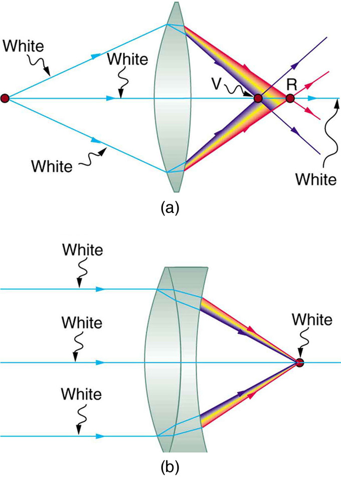
Achromatic Doublet: (a) Chromatic aberration is caused by the dependence of a lens’s index of refraction on color (wavelength). The lens is more powerful for violet (V) than for red (R), producing images with different locations and magnifications. (b) Multiple-lens systems, such as this achromatic doublet, can partially correct chromatic aberrations, but they may require lenses of different materials and add to the expense of optical systems such as cameras.
The Lensmaker’s Equation
The lensmaker’s formula is used to relate the radii of curvature, the thickness, the refractive index, and the focal length of a thick lens.
learning objectives
- Compare idealized thin lenses with real lenses
The Lensmaker’s Equation
Thick Lenses
Unlike idealized thin lenses, real lenses have a finite thickness between their two surfaces of curvature. An ideal thin lens with two surfaces of equal curvature would have zero optical power, meaning that it would neither converge nor diverge light. A lens whose thickness is not negligible is called a thick lens. In this case, we can not simply assume that a light ray is only refracted once while traveling through the lens. Instead the extent of the refraction must be dependent on the thickness of the lens.
Lenses are classified by the curvature of the two optical surfaces. A lens is biconvex (or double convex, or just convex) if both surfaces are convex. If the lens is biconvex, a beam of light travelling parallel to the lens axis and passing through the lens will be converged (or focused) to a spot on the axis, at a certain distance behind the lens (i.e. the focal length). In this case, the lens is called a positive or converging lens. See for a diagram of a positive (converging) lens.
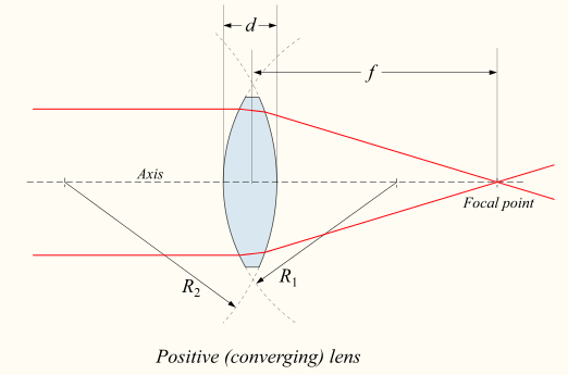
Thick Converging Lens: Diagram of a positive (converging) lens. The lensmaker’s formula relates the radii of curvature, the index of refraction of the lens, the thickness of the lens, and the focal length.
If the lens is biconcave, a beam of light passing through the lens is diverged (spread); the lens is thus called a negative or diverging lens. The beam after passing through the lens appears to be emanating from a particular point on the axis in front of the lens; the distance from this point to the lens is also known as the focal length, although it is negative with respect to the focal length of a converging lens. See for a diagram of a negative (diverging) lens.
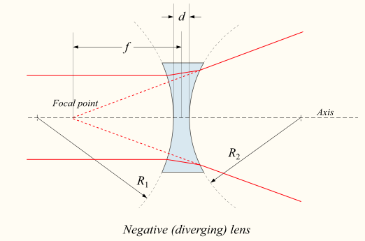
Negative Diverging Lens: Diagram of a negative (diverging) lens. The lensmaker’s formula relates the radii of curvature, the index of refraction of the lens, the thickness of the lens, and the focal length.
The focal length of a thick lens in air can be calculated from the lensmaker’s equation:
\[\mathrm { P } = \dfrac { 1 } { \mathrm { f } } = ( \mathrm { n } - 1 ) \left[ \dfrac { 1 } { \mathrm { R } _ { 1 } } - \dfrac { 1 } { \mathrm { R } _ { 2 } } + \dfrac { ( \mathrm { n } - 1 ) \mathrm { d } } { \mathrm { nR } _ { 1 } \mathrm { R } _ { 2 } } \right]\]
where
- P is the power of the lens,
- f is the focal length of the lens,
- n is the refractive index of the lens material,
- R1is the radius of curvature of the lens surface closest to the light source,
- R2 is the radius of curvature of the lens surface farthest from the light source, d and is the thickness of the lens (the distance along the lens axis between the two surface vertices).
Sign convention of Radii R1 and R2
The signs of the lens’ radii of curvature indicate whether the corresponding surfaces are convex or concave. The sign convention used to represent this varies, but for our treatment if R1 is positive the first surface is convex, and if R1 is negative the surface is concave. The signs are reversed for the back surface of the lens: if R2 is positive the surface is concave, and if R2 is negative the surface is convex. If either radius is infinite, the corresponding surface is flat. With this convention the signs are determined by the shapes of the lens surfaces, and are independent of the direction in which light travels through the lens.
Thin Lens Approximation
The above equation can be greatly simplified if the lens thickness d is very small compared to R1 and R2. In this case, the thin lens approximation can then be made and the lensmaker’s equation can be approximated as
\[\mathrm { P } = \dfrac { 1 } { \mathrm { f } } \approx ( \mathrm { n } - 1 ) \left[ \dfrac { 1 } { \mathrm { R } _ { 1 } } - \frac { 1 } { \mathrm { R } _ { 2 } } \right]\]
The focal length f is positive for converging lenses, and negative for diverging lenses. The reciprocal of the focal length, 1/f, is the optical of the lens. If the focal length is in meters, this gives the optical power in diopters (inverse meters).
Lenses have the same focal length when light travels from the back to the front as when light goes from the front to the back, although other properties of the lens, such as the aberrations are not necessarily the same in both directions.
Refraction Through Lenses
Because the index of refraction of a lens is greater than air, a ray moves towards the perpendicular as it enters and away as it leaves.
learning objectives
- Compare the effect of a convex lens and a concave lens on the light rays
Refraction Through Lenses
Lenses are found in a huge array of optical instruments, ranging from the simple magnifying glass to a camera lens to the lens of the human eye. The word lens derives from the Latin word for lentil bean—the shape of which is similar to that of the convex lens (as shown in ). The convex lens is shaped so that all light rays that enter it parallel to its axis cross one another at a single point on the opposite side of the lens. The axis is defined as a line normal to the lens at its center (as shown in ). Such a lens is called a converging (or convex) lens for the corresponding effect it has on light rays. The expanded view of the path of one ray through the lens illustrates how the ray changes direction both as it enters and as it leaves the lens.
Since the index of refraction of the lens is greater than that of air, the ray moves towards the perpendicular as it enters, and away from the perpendicular as it leaves (this is in accordance with the law of refraction). Due to the lens’s shape, light is thus bent toward the axis at both surfaces. The point at which the rays cross is defined as the focal point F of the lens. The distance from the center of the lens to its focal point is defined as the focal length f of the lens. shows how a converging lens, such as that in a magnifying glass, can concentrate (converge) the nearly parallel light rays from the sun towards a small spot.

Magnifying Glass: Sunlight focused by a converging magnifying glass can burn paper. Light rays from the sun are nearly parallel and cross at the focal point of the lens. The more powerful the lens, the closer to the lens the rays will cross.
The greater effect a lens has on light rays, the more powerful it is said to be. For example, a powerful converging lens will focus parallel light rays closer to itself and will have a smaller focal length than a weak lens. The light will also focus into a smaller, more intense spot for a more powerful lens. The power P of a lens is defined as the inverse of its focal length. In equation form:
\[\mathrm { P } = \dfrac { 1 } { \mathrm { f } }\]
shows the effect of a concave lens on rays of light entering it parallel to its axis (the path taken by ray 2 in the figure is the axis of the lens). The concave lens is a diverging lens, because it causes the light rays to bend away (diverge) from its axis. In this case, the lens is shaped so that all light rays entering it parallel to its axis appear to originate from the same point F, defined as the focal point of a diverging lens. The distance from the center of the lens to the focal point is again called the focal length f of the lens. Note that the focal length and power of a diverging lens are defined as negative. For example, if the distance to F in is 5.00 cm, then the focal length is f=–5.00 cm and the power of the lens is P=–20 D. The expanded view of the path of one ray through the lens illustrates how the shape of the lens (given the law of refraction) causes the ray to follow its particular path and be diverged.
In subsequent sections we will examine the technique of ray tracing to describe the formation of images by lenses. Additionally, we will explore how image locations and characteristics can be quantified with the help of a set of geometric optics equations.
Key Points
- When light interacts with objects several times as large as its wavelength, it travels in straight lines and acts like a ray. A ray is simply a straight line that originates at a point.
- Ray tracing is the method for determining the paths light takes through matter, such as optical systems that include lenses.
- A thin lens is defined as one with a thickness that allows rays to refract, as illustrated in, but that does not allow properties such as dispersion and aberrations. An ideal thin lens has two refracting surfaces but the lens is thin enough to assume that light rays bend only once.
- There are five basic rules for tracing rays through a lens.
- Ray tracing can be used to construct an image from the light rays originating from an object that pass through a lens. The image is located at the point where the rays cross. By choosing several points from an object the entire image can be constructed.
- We define do to be the object distance, the distance of an object from the center of a lens. Image distance di is defined to be the distance of the image from the center of a lens. The height of the object and height of the image are given the symbols ho and hi, respectively.
- The thin lens equation quickly provides the relation between di, do, and the focal length f. It can be derived from a geometric analysis of ray tracing for thin lenses and is given by \(\frac { 1 } { \mathrm { d } _ { \mathrm { o } } } + \frac { 1 } { \mathrm { d } _ { \mathrm { i } } } = \frac { 1 } { \mathrm { f } }\).
- The magnification m of an image is the ratio between the image and object height (hi/ho). The magnification is related to do, di, ho, and hi by the following relation: \(\frac { \mathrm { h } _ { \mathrm { i } } } { \mathrm { h } _ { \mathrm { o } } } = - \frac { \mathrm { d } _ { \mathrm { i } } } { \mathrm { d } _ { \mathrm { o } } } = \mathrm { m }\).
- The use of multiple elements allows for the correction of more optical aberrations, such as the chromatic abberation caused by the wavelength -dependent index of refraction in glass, than is possible using a single lens.
- If the lenses of focal lengths f1 and f2are “thin”, the combined focal length f of the lenses is given by \(\frac { 1 } { f } = \frac { 1 } { f _ { 1 } } + \frac { 1 } { f _ { 2 } }\) while if the lenses are separated by some distance d then the combined focal length is given by \(\frac { 1 } { f } = \frac { 1 } { f _ { 1 } } + \frac { 1 } { f _ { 2 } } - \frac { d } { f _ { 1 } f _ { 2 } }\).
- If the separation distance is equal to the sum of the focal lengths (d = f1+f2), the combined focal length is infinite. This corresponds to a pair of lenses that transform a collimated beam into another collimated beam. This type of system is called an afocal system (a simple optical telescope).
- An achromatic doublet is a kind of compound lens designed to bring two wavelengths (typically red and blue/violet) into focus in the same plane. This (partially) corrects for the chromatic aberration found in a single simple lens. See.
- If a lens is biconvex, a beam of light travelling parallel to the lens axis and passing through the lens will be focused to a spot on the axis, at a certain distance behind the lens (i.e. the focal length ). In this case, the lens is called a positive or converging lens. See.
- If a lens is biconcave, a beam of light passing through the lens is diverged (spread); the lens is thus called a negative or diverging lens. See.
- The focal length of a thick lens in air can be calculated from the lensmaker’s equation: \(\mathrm { P } = \frac { 1 } { \mathrm { f } } = ( \mathrm { n } - 1 ) \left[ \frac { 1 } { \mathrm { R } _ { 1 } } - \frac { 1 } { \mathrm { R } _ { 2 } } + \frac { ( \mathrm { n } - 1 ) \mathrm { d } } { \mathrm { nR } _ { 1 } \mathrm { R } _ { 2 } } \right]\).
- The signs of the lens’ radii of curvature indicate whether the corresponding surfaces are convex or concave. The signs are reversed for the back surface of the lens: if R2 is positive the surface is concave, and if R2 is negative the surface is convex.
- The lensmaker’s equation can be greatly simplified if the lens thickness d is very small compared to R1 and R2. In this case, the thin lens approximation can then be made and the lensmaker’s equation can be approximated as \(P = \frac { 1 } { f } \approx ( n - 1 ) \left[ \frac { 1 } { R _ { 1 } } - \frac { 1 } { R _ { 2 } } \right]\).
- Recall that the a ray will bend as it enters a medium with a different refractive index. Since the refractive index of a lens is greater than air, a light ray will move towards the perpendicular as it enters and away as it leaves.
- A convex lens has been shaped so that all light rays that enter it parallel to its axis cross one another at a single point on the opposite side of the lens (the focal point ). Such a lens is called a converging (or convex) lens for the converging effect it has on light rays. See.
- A concave lens is a diverging lens, because it causes the light rays to bend away (diverge) from its axis. shows the effect it has on rays of light that enter it parallel to its axis (the path taken by ray 2 in the figure is the axis of the lens).
- The greater effect a lens has on light rays, the more powerful it is said to be. A powerful converging lens will focus parallel light rays closer to itself and will have a smaller focal length than a weak lens. The power of a lens is given by the equation \(\mathrm { P } = \frac { 1 } { \mathrm { f } }\).
Key Terms
- focal point: A focus—a point at which rays of light or other radiation converge.
- ray tracing: A technique used in optics for analysis of optical systems.
- thin lens: A thin lens is defined to be one whose thickness allows rays to refract but does not allow properties such as dispersion and aberrations.
- thin lens equation: Relates object distance do, image distance di, and focal length f: \( \frac { 1 } { \mathrm { d } _ { \mathrm { o } } } + \frac { 1 } { \mathrm { d } _ { \mathrm { i } } } = \frac { 1 } { \mathrm { f } }\)
- image distance: The distance of the image from the center of the lens.
- magnification: The apparent enlargement of an object in an image.
- aberration: The convergence to different foci, by a lens or mirror, of rays of light emanating from one and the same point, or the deviation of such rays from a single focus; a defect in a focusing mechanism that prevents the intended focal point.
- afocal system: An optical system that produces no net convergence or divergence of the beam, i.e. has an infinite effective focal length. This type of system can be created with a pair of optical elements where the distance between the elements is equal to the sum of each element’s focal length (d = f1+f2).
- achromatic doublet: A type of lens made up of two simple lenses paired together designed so that the chromatic aberration of each lens partially offsets the other; in this way light in a range of wavelengths may be brought to the same focus.
- thick lens: Lenses whose thicknesses are not negligible (i.e., one cannot make the simple assumption that a light ray is refracted only once in the lens).
- surface vertices: The points where each surface crosses the optical axis. They are important primarily because they are the physically measurable parameters for the position of the optical elements, and so the positions of the other cardinal points must be known with respect to the vertices to describe the physical system.
- convex lens: A lens having at least one convex surface, such that light passing through it, may be brought to a focus.
- concave lens: A lens having at least one concave surface, such that light rays passing through it bend away from its optical axis.
LICENSES AND ATTRIBUTIONS
CC LICENSED CONTENT, SHARED PREVIOUSLY
- Curation and Revision. Provided by: Boundless.com. License: CC BY-SA: Attribution-ShareAlike
CC LICENSED CONTENT, SPECIFIC ATTRIBUTION
- OpenStax College, College Physics. September 18, 2013. Provided by: OpenStax CNX. Located at: http://cnx.org/content/m42452/latest/?collection=col11406/1.7. License: CC BY: Attribution
- OpenStax College, Image Formation by Lenses. September 18, 2013. Provided by: OpenStax CNX. Located at: http://cnx.org/content/m42470/latest/. License: CC BY: Attribution
- Rory Adams, Free High School Science Texts Project, Mark Horner, and Heather Williams, Geometrical Optics - Grade 10. September 18, 2013. Provided by: OpenStax CNX. Located at: http://cnx.org/content/m32826/latest/. License: CC BY: Attribution
- Simple lens. Provided by: Wikipedia. Located at: en.Wikipedia.org/wiki/Simple_lens. License: CC BY-SA: Attribution-ShareAlike
- Lens (optics). Provided by: Wikipedia. Located at: en.Wikipedia.org/wiki/Lens_(optics). License: CC BY-SA: Attribution-ShareAlike
- Ray tracing (physics). Provided by: Wikipedia. Located at: en.Wikipedia.org/wiki/Ray_tracing_(physics). License: CC BY-SA: Attribution-ShareAlike
- Thin lens approximation. Provided by: Wikipedia. Located at: en.Wikipedia.org/wiki/Thin_lens_approximation. License: CC BY-SA: Attribution-ShareAlike
- Boundless. Provided by: Boundless Learning. Located at: www.boundless.com//physics/definition/thin-lens. License: CC BY-SA: Attribution-ShareAlike
- ray tracing. Provided by: Wiktionary. Located at: en.wiktionary.org/wiki/ray_tracing. License: CC BY-SA: Attribution-ShareAlike
- focal point. Provided by: Wiktionary. Located at: en.wiktionary.org/wiki/focal_point. License: CC BY-SA: Attribution-ShareAlike
- OpenStax College, Image Formation by Lenses. December 29, 2012. Provided by: OpenStax CNX. Located at: http://cnx.org/content/m42470/latest/#import-auto-id1625442. License: CC BY: Attribution
- OpenStax College, Image Formation by Lenses. December 29, 2012. Provided by: OpenStax CNX. Located at: http://cnx.org/content/m42470/latest/#import-auto-id1625442. License: CC BY: Attribution
- OpenStax College, Image Formation by Lenses. December 29, 2012. Provided by: OpenStax CNX. Located at: http://cnx.org/content/m42470/latest/#import-auto-id1625442. License: CC BY: Attribution
- Ray Diagrams, Concave Lens and Convex Mirror. Located at: http://www.youtube.com/watch?v=c2GFG6cvPew. License: Public Domain: No Known Copyright. License Terms: Standard YouTube license
- Thin lens approximation. Provided by: Wikipedia. Located at: en.Wikipedia.org/wiki/Thin_lens_approximation. License: CC BY-SA: Attribution-ShareAlike
- Magnification. Provided by: Wikipedia. Located at: en.Wikipedia.org/wiki/Magnification%23Calculating_the_magnification_of_optical_systems. License: CC BY-SA: Attribution-ShareAlike
- OpenStax College, College Physics. September 18, 2013. Provided by: OpenStax CNX. Located at: http://cnx.org/content/m42470/latest/?collection=col11406/1.7. License: CC BY: Attribution
- Boundless. Provided by: Boundless Learning. Located at: www.boundless.com//physics/definition/image-distance. License: CC BY-SA: Attribution-ShareAlike
- Boundless. Provided by: Boundless Learning. Located at: www.boundless.com//physics/definition/thin-lens-equation. License: CC BY-SA: Attribution-ShareAlike
- magnification. Provided by: Wiktionary. Located at: en.wiktionary.org/wiki/magnification. License: CC BY-SA: Attribution-ShareAlike
- OpenStax College, Image Formation by Lenses. December 29, 2012. Provided by: OpenStax CNX. Located at: http://cnx.org/content/m42470/latest/#import-auto-id1625442. License: CC BY: Attribution
- OpenStax College, Image Formation by Lenses. December 29, 2012. Provided by: OpenStax CNX. Located at: http://cnx.org/content/m42470/latest/#import-auto-id1625442. License: CC BY: Attribution
- OpenStax College, Image Formation by Lenses. December 29, 2012. Provided by: OpenStax CNX. Located at: http://cnx.org/content/m42470/latest/#import-auto-id1625442. License: CC BY: Attribution
- Ray Diagrams, Concave Lens and Convex Mirror. Located at: http://www.youtube.com/watch?v=c2GFG6cvPew. License: Public Domain: No Known Copyright. License Terms: Standard YouTube license
- OpenStax College, College Physics. December 30, 2012. Provided by: OpenStax CNX. Located at: http://cnx.org/content/m42470/latest/?collection=col11406/1.7. License: CC BY: Attribution
- Thin Lens Equations for a Convex Lens. Located at: http://www.youtube.com/watch?v=u4zhWFALZ-Q. License: Public Domain: No Known Copyright. License Terms: Standard YouTube license
- Achromat. Provided by: Wikipedia. Located at: http://en.Wikipedia.org/wiki/Achromat. License: CC BY-SA: Attribution-ShareAlike
- OpenStax College, College Physics. September 17, 2013. Provided by: OpenStax CNX. Located at: http://cnx.org/content/m42292/latest/?collection=col11406/1.7. License: CC BY: Attribution
- Doublet (lens). Provided by: Wikipedia. Located at: en.Wikipedia.org/wiki/Doublet_(lens). License: CC BY-SA: Attribution-ShareAlike
- Lens (optics). Provided by: Wikipedia. Located at: en.Wikipedia.org/wiki/Lens_(optics)%23Compound_lenses. License: CC BY-SA: Attribution-ShareAlike
- aberration. Provided by: Wiktionary. Located at: en.wiktionary.org/wiki/aberration. License: CC BY-SA: Attribution-ShareAlike
- achromatic doublet. Provided by: Wikipedia. Located at: en.Wikipedia.org/wiki/achromatic%20doublet. License: CC BY-SA: Attribution-ShareAlike
- afocal system. Provided by: Wikipedia. Located at: en.Wikipedia.org/wiki/afocal%20system. License: CC BY-SA: Attribution-ShareAlike
- OpenStax College, Image Formation by Lenses. December 29, 2012. Provided by: OpenStax CNX. Located at: http://cnx.org/content/m42470/latest/#import-auto-id1625442. License: CC BY: Attribution
- OpenStax College, Image Formation by Lenses. December 29, 2012. Provided by: OpenStax CNX. Located at: http://cnx.org/content/m42470/latest/#import-auto-id1625442. License: CC BY: Attribution
- OpenStax College, Image Formation by Lenses. December 29, 2012. Provided by: OpenStax CNX. Located at: http://cnx.org/content/m42470/latest/#import-auto-id1625442. License: CC BY: Attribution
- Ray Diagrams, Concave Lens and Convex Mirror. Located at: http://www.youtube.com/watch?v=c2GFG6cvPew. License: Public Domain: No Known Copyright. License Terms: Standard YouTube license
- OpenStax College, College Physics. December 30, 2012. Provided by: OpenStax CNX. Located at: http://cnx.org/content/m42470/latest/?collection=col11406/1.7. License: CC BY: Attribution
- Thin Lens Equations for a Convex Lens. Located at: http://www.youtube.com/watch?v=u4zhWFALZ-Q. License: Public Domain: No Known Copyright. License Terms: Standard YouTube license
- OpenStax College, College Physics. January 6, 2013. Provided by: OpenStax CNX. Located at: http://cnx.org/content/m42292/latest/?collection=col11406/1.7. License: CC BY: Attribution
- Refracting telescope. Provided by: Wikipedia. Located at: en.Wikipedia.org/wiki/Refracting_telescope. License: Public Domain: No Known Copyright
- Lensmaker's equation. Provided by: Wikipedia. Located at: en.Wikipedia.org/wiki/Lensmaker's_equation%23Lensmaker.27s_equation. License: CC BY-SA: Attribution-ShareAlike
- Boundless. Provided by: Boundless Learning. Located at: www.boundless.com//physics/definition/thick-lens. License: CC BY-SA: Attribution-ShareAlike
- surface vertices. Provided by: Wikipedia. Located at: en.Wikipedia.org/wiki/surface%20vertices. License: CC BY-SA: Attribution-ShareAlike
- OpenStax College, Image Formation by Lenses. December 29, 2012. Provided by: OpenStax CNX. Located at: http://cnx.org/content/m42470/latest/#import-auto-id1625442. License: CC BY: Attribution
- OpenStax College, Image Formation by Lenses. December 29, 2012. Provided by: OpenStax CNX. Located at: http://cnx.org/content/m42470/latest/#import-auto-id1625442. License: CC BY: Attribution
- OpenStax College, Image Formation by Lenses. December 29, 2012. Provided by: OpenStax CNX. Located at: http://cnx.org/content/m42470/latest/#import-auto-id1625442. License: CC BY: Attribution
- Ray Diagrams, Concave Lens and Convex Mirror. Located at: http://www.youtube.com/watch?v=c2GFG6cvPew. License: Public Domain: No Known Copyright. License Terms: Standard YouTube license
- OpenStax College, College Physics. December 30, 2012. Provided by: OpenStax CNX. Located at: http://cnx.org/content/m42470/latest/?collection=col11406/1.7. License: CC BY: Attribution
- Thin Lens Equations for a Convex Lens. Located at: http://www.youtube.com/watch?v=u4zhWFALZ-Q. License: Public Domain: No Known Copyright. License Terms: Standard YouTube license
- OpenStax College, College Physics. January 6, 2013. Provided by: OpenStax CNX. Located at: http://cnx.org/content/m42292/latest/?collection=col11406/1.7. License: CC BY: Attribution
- Refracting telescope. Provided by: Wikipedia. Located at: http://en.Wikipedia.org/wiki/Refracting_telescope. License: Public Domain: No Known Copyright
- Lensmaker's equation. Provided by: Wikipedia. Located at: en.Wikipedia.org/wiki/Lensmaker's_equation%23Lensmaker.27s_equation. License: Public Domain: No Known Copyright
- Lensmaker's equation. Provided by: Wikipedia. Located at: en.Wikipedia.org/wiki/Lensmaker's_equation%23Lensmaker.27s_equation. License: Public Domain: No Known Copyright
- Refraction. Provided by: Wikipedia. Located at: en.Wikipedia.org/wiki/Refraction. License: CC BY-SA: Attribution-ShareAlike
- OpenStax College, College Physics. September 18, 2013. Provided by: OpenStax CNX. Located at: http://cnx.org/content/m42459/latest/?collection=col11406/1.7. License: CC BY: Attribution
- OpenStax College, College Physics. September 18, 2013. Provided by: OpenStax CNX. Located at: http://cnx.org/content/m42470/latest/?collection=col11406/1.7. License: CC BY: Attribution
- Lens (optics). Provided by: Wikipedia. Located at: en.Wikipedia.org/wiki/Lens_(optics). License: CC BY-SA: Attribution-ShareAlike
- Boundless. Provided by: Boundless Learning. Located at: www.boundless.com//physics/definition/concave-lens. License: CC BY-SA: Attribution-ShareAlike
- convex lens. Provided by: Wiktionary. Located at: en.wiktionary.org/wiki/convex_lens. License: CC BY-SA: Attribution-ShareAlike
- focal point. Provided by: Wiktionary. Located at: en.wiktionary.org/wiki/focal_point. License: CC BY-SA: Attribution-ShareAlike
- OpenStax College, Image Formation by Lenses. December 29, 2012. Provided by: OpenStax CNX. Located at: http://cnx.org/content/m42470/latest/#import-auto-id1625442. License: CC BY: Attribution
- OpenStax College, Image Formation by Lenses. December 29, 2012. Provided by: OpenStax CNX. Located at: http://cnx.org/content/m42470/latest/#import-auto-id1625442. License: CC BY: Attribution
- OpenStax College, Image Formation by Lenses. December 29, 2012. Provided by: OpenStax CNX. Located at: http://cnx.org/content/m42470/latest/#import-auto-id1625442. License: CC BY: Attribution
- Ray Diagrams, Concave Lens and Convex Mirror. Located at: http://www.youtube.com/watch?v=c2GFG6cvPew. License: Public Domain: No Known Copyright. License Terms: Standard YouTube license
- OpenStax College, College Physics. December 30, 2012. Provided by: OpenStax CNX. Located at: http://cnx.org/content/m42470/latest/?collection=col11406/1.7. License: CC BY: Attribution
- Thin Lens Equations for a Convex Lens. Located at: http://www.youtube.com/watch?v=u4zhWFALZ-Q. License: Public Domain: No Known Copyright. License Terms: Standard YouTube license
- OpenStax College, College Physics. January 6, 2013. Provided by: OpenStax CNX. Located at: http://cnx.org/content/m42292/latest/?collection=col11406/1.7. License: CC BY: Attribution
- Refracting telescope. Provided by: Wikipedia. Located at: http://en.Wikipedia.org/wiki/Refracting_telescope. License: Public Domain: No Known Copyright
- Lensmaker's equation. Provided by: Wikipedia. Located at: en.Wikipedia.org/wiki/Lensmaker's_equation%23Lensmaker.27s_equation. License: Public Domain: No Known Copyright
- Lensmaker's equation. Provided by: Wikipedia. Located at: en.Wikipedia.org/wiki/Lensmaker's_equation%23Lensmaker.27s_equation. License: Public Domain: No Known Copyright
- OpenStax College, College Physics. January 1, 2013. Provided by: OpenStax CNX. Located at: http://cnx.org/content/m42470/latest/?collection=col11406/1.7. License: CC BY: Attribution