19.5: Alternating Currents
- Page ID
- 14561
\( \newcommand{\vecs}[1]{\overset { \scriptstyle \rightharpoonup} {\mathbf{#1}} } \)
\( \newcommand{\vecd}[1]{\overset{-\!-\!\rightharpoonup}{\vphantom{a}\smash {#1}}} \)
\( \newcommand{\dsum}{\displaystyle\sum\limits} \)
\( \newcommand{\dint}{\displaystyle\int\limits} \)
\( \newcommand{\dlim}{\displaystyle\lim\limits} \)
\( \newcommand{\id}{\mathrm{id}}\) \( \newcommand{\Span}{\mathrm{span}}\)
( \newcommand{\kernel}{\mathrm{null}\,}\) \( \newcommand{\range}{\mathrm{range}\,}\)
\( \newcommand{\RealPart}{\mathrm{Re}}\) \( \newcommand{\ImaginaryPart}{\mathrm{Im}}\)
\( \newcommand{\Argument}{\mathrm{Arg}}\) \( \newcommand{\norm}[1]{\| #1 \|}\)
\( \newcommand{\inner}[2]{\langle #1, #2 \rangle}\)
\( \newcommand{\Span}{\mathrm{span}}\)
\( \newcommand{\id}{\mathrm{id}}\)
\( \newcommand{\Span}{\mathrm{span}}\)
\( \newcommand{\kernel}{\mathrm{null}\,}\)
\( \newcommand{\range}{\mathrm{range}\,}\)
\( \newcommand{\RealPart}{\mathrm{Re}}\)
\( \newcommand{\ImaginaryPart}{\mathrm{Im}}\)
\( \newcommand{\Argument}{\mathrm{Arg}}\)
\( \newcommand{\norm}[1]{\| #1 \|}\)
\( \newcommand{\inner}[2]{\langle #1, #2 \rangle}\)
\( \newcommand{\Span}{\mathrm{span}}\) \( \newcommand{\AA}{\unicode[.8,0]{x212B}}\)
\( \newcommand{\vectorA}[1]{\vec{#1}} % arrow\)
\( \newcommand{\vectorAt}[1]{\vec{\text{#1}}} % arrow\)
\( \newcommand{\vectorB}[1]{\overset { \scriptstyle \rightharpoonup} {\mathbf{#1}} } \)
\( \newcommand{\vectorC}[1]{\textbf{#1}} \)
\( \newcommand{\vectorD}[1]{\overrightarrow{#1}} \)
\( \newcommand{\vectorDt}[1]{\overrightarrow{\text{#1}}} \)
\( \newcommand{\vectE}[1]{\overset{-\!-\!\rightharpoonup}{\vphantom{a}\smash{\mathbf {#1}}}} \)
\( \newcommand{\vecs}[1]{\overset { \scriptstyle \rightharpoonup} {\mathbf{#1}} } \)
\(\newcommand{\longvect}{\overrightarrow}\)
\( \newcommand{\vecd}[1]{\overset{-\!-\!\rightharpoonup}{\vphantom{a}\smash {#1}}} \)
\(\newcommand{\avec}{\mathbf a}\) \(\newcommand{\bvec}{\mathbf b}\) \(\newcommand{\cvec}{\mathbf c}\) \(\newcommand{\dvec}{\mathbf d}\) \(\newcommand{\dtil}{\widetilde{\mathbf d}}\) \(\newcommand{\evec}{\mathbf e}\) \(\newcommand{\fvec}{\mathbf f}\) \(\newcommand{\nvec}{\mathbf n}\) \(\newcommand{\pvec}{\mathbf p}\) \(\newcommand{\qvec}{\mathbf q}\) \(\newcommand{\svec}{\mathbf s}\) \(\newcommand{\tvec}{\mathbf t}\) \(\newcommand{\uvec}{\mathbf u}\) \(\newcommand{\vvec}{\mathbf v}\) \(\newcommand{\wvec}{\mathbf w}\) \(\newcommand{\xvec}{\mathbf x}\) \(\newcommand{\yvec}{\mathbf y}\) \(\newcommand{\zvec}{\mathbf z}\) \(\newcommand{\rvec}{\mathbf r}\) \(\newcommand{\mvec}{\mathbf m}\) \(\newcommand{\zerovec}{\mathbf 0}\) \(\newcommand{\onevec}{\mathbf 1}\) \(\newcommand{\real}{\mathbb R}\) \(\newcommand{\twovec}[2]{\left[\begin{array}{r}#1 \\ #2 \end{array}\right]}\) \(\newcommand{\ctwovec}[2]{\left[\begin{array}{c}#1 \\ #2 \end{array}\right]}\) \(\newcommand{\threevec}[3]{\left[\begin{array}{r}#1 \\ #2 \\ #3 \end{array}\right]}\) \(\newcommand{\cthreevec}[3]{\left[\begin{array}{c}#1 \\ #2 \\ #3 \end{array}\right]}\) \(\newcommand{\fourvec}[4]{\left[\begin{array}{r}#1 \\ #2 \\ #3 \\ #4 \end{array}\right]}\) \(\newcommand{\cfourvec}[4]{\left[\begin{array}{c}#1 \\ #2 \\ #3 \\ #4 \end{array}\right]}\) \(\newcommand{\fivevec}[5]{\left[\begin{array}{r}#1 \\ #2 \\ #3 \\ #4 \\ #5 \\ \end{array}\right]}\) \(\newcommand{\cfivevec}[5]{\left[\begin{array}{c}#1 \\ #2 \\ #3 \\ #4 \\ #5 \\ \end{array}\right]}\) \(\newcommand{\mattwo}[4]{\left[\begin{array}{rr}#1 \amp #2 \\ #3 \amp #4 \\ \end{array}\right]}\) \(\newcommand{\laspan}[1]{\text{Span}\{#1\}}\) \(\newcommand{\bcal}{\cal B}\) \(\newcommand{\ccal}{\cal C}\) \(\newcommand{\scal}{\cal S}\) \(\newcommand{\wcal}{\cal W}\) \(\newcommand{\ecal}{\cal E}\) \(\newcommand{\coords}[2]{\left\{#1\right\}_{#2}}\) \(\newcommand{\gray}[1]{\color{gray}{#1}}\) \(\newcommand{\lgray}[1]{\color{lightgray}{#1}}\) \(\newcommand{\rank}{\operatorname{rank}}\) \(\newcommand{\row}{\text{Row}}\) \(\newcommand{\col}{\text{Col}}\) \(\renewcommand{\row}{\text{Row}}\) \(\newcommand{\nul}{\text{Nul}}\) \(\newcommand{\var}{\text{Var}}\) \(\newcommand{\corr}{\text{corr}}\) \(\newcommand{\len}[1]{\left|#1\right|}\) \(\newcommand{\bbar}{\overline{\bvec}}\) \(\newcommand{\bhat}{\widehat{\bvec}}\) \(\newcommand{\bperp}{\bvec^\perp}\) \(\newcommand{\xhat}{\widehat{\xvec}}\) \(\newcommand{\vhat}{\widehat{\vvec}}\) \(\newcommand{\uhat}{\widehat{\uvec}}\) \(\newcommand{\what}{\widehat{\wvec}}\) \(\newcommand{\Sighat}{\widehat{\Sigma}}\) \(\newcommand{\lt}{<}\) \(\newcommand{\gt}{>}\) \(\newcommand{\amp}{&}\) \(\definecolor{fillinmathshade}{gray}{0.9}\)learning objectives
- Discuss applications of a phase vector
Phasors
Complex numbers play an important role in physics. Usually, complex numbers are written in terms of their real part plus the imaginary part. For example, \(\mathrm{a+bi}\) where a and b are real numbers, and ii signals the imaginary part. However, it is often practical to write complex numbers in the form of an exponential called a phasor.
In physics, a phase vector, or phasor, is a representation of a sinusoidal function whose amplitude (A), frequency (ω), and phase (θ) are time-invariant, as diagramed in. Phasors separate the dependencies on \(A\), \(ω\), and \(θ\) into three independent factors. This can be particularly useful because the frequency factor (which includes the time-dependence of the sinusoid) is often common to all the components of a linear combination of sinusoids. In those situations, phasors allow this common feature to be factored out, leaving just the A and θ features. The result is that trigonometry reduces to algebra, and linear differential equations become algebraic ones. The term phasor therefore often refers to just those two factors.
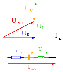
Phasor Diagram: An example of series RLC circuit and respective phasor diagram for a specific ω. Electrical engineers, electronics engineers, electronic engineering technicians and aircraft engineers all use phasor diagrams to visualize complex constants and variables (phasors). Like vectors, arrows drawn on graph paper or computer displays represent phasors.
Phasors are often used in electrical systems when considering voltages and currents that vary sinusoidally in time, such as in RLC circuits.
Definition
Sinusoids can be represented mathematically as the sum of two complex-valued functions:
\[\mathrm { A } \cdot \cos ( \omega t + \theta ) = \mathrm { A } \cdot \dfrac { \mathrm { e } ^ { \mathrm { i } ( \omega t + \theta ) } + \mathrm { e } ^ { - \mathrm { i } ( \omega t + \theta ) } } { 2 }\]
or as the real part of one of the functions:
\[\mathrm { A } \cdot \cos ( \omega t + \theta ) = \operatorname { Re } \left\{ \mathrm { A } \cdot \mathrm { e } ^ { \mathrm { i } ( \omega t + \theta ) } \right\} = \operatorname { Re } \left\{ \mathrm { A } \mathrm { e } ^ { \mathrm { i } \theta } \cdot \mathrm { e } ^ { \mathrm { i } \omega t } \right\}\]
As indicated above, phasor can refer to either Aeiθ⋅eiωtAeiθ⋅eiωt or just the complex constant, AeiθAeiθ. In the latter case, it is understood to be a shorthand notation, encoding the amplitude and phase of an underlying sinusoid.
Phasor Representation of Signals
There are two key ideas behind the phasor representation of a signal:
- a real, time-varying signal may be represented by a complex, time-varying signal; and
- a complex, time-varying signal may be represented as the product of a complex number that is independent of time and a complex signal that is dependent on time.
The signal:
\[\mathrm { x } ( \mathrm { t } ) = \operatorname { Acos } ( \omega \mathrm{t} + \theta )\]
illustrated in the figure below is a cosinusoidal signal with amplitude A, frequency, and phase θ. The amplitude A characterizes the peak-to-peak swing of 2A, the angular frequency ω characterizes the period T=2π/ω between negative- to-positive zero crossings (or positive peaks or negative peaks), and the phase θ characterizes the time τ=−θ/ω when the signal reaches its first peak. With so defined, the signal x(t) may also be written as
\[\mathrm { x } ( \mathrm { t } ) = \operatorname { Acos } ( \mathrm { t } - \tau )\]
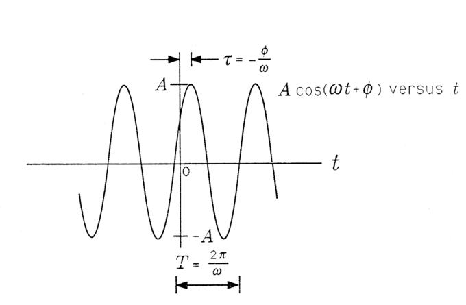
Cosinusoidal Signal: A Cosinusoidal Signal.
When τ is positive, then τ is a “time delay” that describes the time (greater than zero) when the first peak is achieved. When τ is negative, then τ is a “time advance” that describes the time (less than zero) when the last peak was achieved. With the substitution =2π/T we obtain a third way of writing x(t):
\[\mathrm { x } ( \mathrm { t } ) = \operatorname { Acos } \frac { 2 \pi } { \mathrm { T } } ( \mathrm { t } - \boldsymbol { \tau } )\]
In this form the signal is easy to plot. Simply draw a cosinusoidal wave with amplitude A and period T; then strike the origin (t=0) so that the signal reaches its peak at τ. In summary, the parameters that determine a cosinusoidal signal have the following units:
- A, arbitrary (e.g., volts or meters/sec, depending upon the application )
- ω, in radians /sec (rad/sec)
- T, in seconds (sec)
- θ, in radians (rad)
- τ, in seconds (sec)
Sinusoidal Steady State and the Series RLC CircuitPhasors may be used to analyze the behavior of electrical and mechanical systems that have reached a kind of equilibrium called sinusoidal steady state.
In the sinusoidal steady state, every voltage and current (or force and velocity) in a system is sinusoidal with angular frequency ω. However, the amplitudes and phases of these sinusoidal voltages and currents are all different.
For example, the voltage across a resistor might lead the voltage across a capacitor by 90∘ and lag the voltage across an inductor by 90∘. In order to make our application of phasors to electrical systems concrete, we consider the series RLC circuit illustrated in. The arrow labeled i(t) denotes a current that flows in response to the voltage applied.
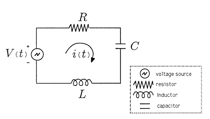
Series RLC Circuit: Series RLC Circuit.
We will assume that the voltage source is an audio oscillator that produces the voltage:
\[\mathrm { V } ( \mathrm { t } ) = \operatorname { Acos } ( \omega \mathrm { t } + \theta )\]
We represent this voltage as the complex signal:
\[\mathrm { V } ( \mathrm { t } ) \leftrightarrow \mathrm { A } \mathrm { e } ^ { \mathrm { i } \theta } \cdot \mathrm { e } ^ { \mathrm { i } \omega \mathrm { t } }\]
and give it the phasor representation,
\[\mathrm { V } ( \mathrm { t } ) \leftrightarrow \mathrm { V } ; \mathrm { V } = \mathrm { A } \mathrm { e } ^ { \mathrm { i } \theta }\]
We then describe the voltage source by the phasor V and remember that we can always compute the actual voltage by multiplying by eiωtand taking the real part.
Root Mean Square Values
The root mean square (RMS) voltage or current is the time-averaged voltage or current in an AC system.
learning objectives
- Relate the root mean square voltage and current in an alternating circut with the peak voltage and current and the average power
Root Mean Square Values and Alternating Current
Recall that in the case of alternating current (AC) the flow of electric charge periodically reverses direction. Unlike direct current (DC), where the currents and voltages are constant, AC currents and voltages vary over time. Recall that most residential and commercial power sources use AC. It is often the case that we wish to know the time averagedcurrent, or voltage. Given the current or voltage as a function of time, we can take the root mean square over time to report the average quantities.
Definition
The root mean square (abbreviated RMS or rms), also known as the quadratic mean, is a statistical measure of the magnitude of a varying quantity. It is especially useful when the function alternates between positive and negative values, e.g., sinusoids.The RMS value of a set of values (or a continuous-time function such as a sinusoid) is the square root of the arithmetic mean of the squares of the original values (or the square of the function). In the case of a set of n values {x1,x2,….,xn}, the RMS value is given by this formula:
\[\mathrm { x } _ { \mathrm { rms } } = \sqrt { \dfrac { 1 } { \mathrm { n } } \left( \mathrm { x } _ { 1 } ^ { 2 } + \mathrm { x } _ { 2 } ^ { 2 } + \cdots + \mathrm { x } _ { \mathrm { n } } ^ { 2 } \right) }\]
The corresponding formula for a continuous function f(t)defined over the interval T1 ≤ t ≤ T2 is as follows:
\[\mathrm { f } _ { \mathrm { rms } } = \sqrt { \dfrac { 1 } { \mathrm { T } _ { 2 } - \mathrm { T } _ { 1 } } \int _ { \mathrm { T } _ { 1 } } ^ { \mathrm { T } _ { 2 } } [ \mathrm { t } ( \mathrm { t } ) ] ^ { 2 } \mathrm { d } \mathrm { t } }\]
The RMS for a function over all time is below.
\[\mathrm { f } _ { \mathrm { rms } } = \lim _ { T \rightarrow \infty } \sqrt { \dfrac { 1 } { \mathrm { T } } \int _ { 0 } ^ { \mathrm { T } } [ \mathrm { t } ( \mathrm { t } ) ] ^ { 2 } \mathrm { d } t }\]
The RMS over all time of a periodic function is equal to the RMS of one period of the function. The RMS value of a continuous function or signal can be approximated by taking the RMS of a series of equally spaced samples.
Application to Voltage and Current
Consider the case of sinusoidally varying voltage:
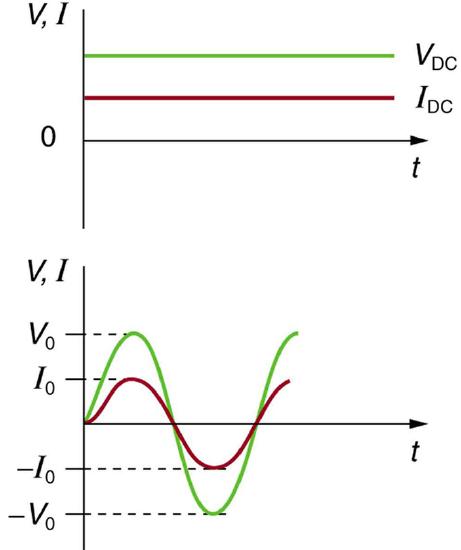
Sinusoidal Voltage and Current: (a) DC voltage and current are constant in time, once the current is established. (b) A graph of voltage and current versus time for 60-Hz AC power. The voltage and current are sinusoidal and are in phase for a simple resistance circuit. The frequencies and peak voltages of AC sources differ greatly.
\[\mathrm { V } = \mathrm { V } _ { 0 } \sin ( 2 \pi \mathrm { ft } )\]
V is the voltage at time t, V0 is the peak voltage, and f is the frequency in hertz. For this simple resistance circuit, I=V/R, and so the AC current is as follows:
\[\mathbf { I } = \mathbf { I } _ { 0 } \sin ( 2 \pi \mathrm { ft } )\]
Here, I is the current at time t, and I0=V0/R is the peak current. Now using the definition above, let’s calculate the rms voltage and rms current. First, we have
\[\mathrm { V } _ { \mathrm { rms } } = \sqrt { \dfrac { 1 } { \mathrm { T } _ { 2 } - \mathrm { T } _ { 1 } } } \int _ { \mathrm { T } _ { 1 } } ^ { \mathrm { T } _ { 2 } } \left[ \mathrm { V } _ { 0 } \sin ( \omega \mathrm { t } ) \right] ^ { 2 } \mathrm { d } \mathrm { t }\]
Here, we have replaced 2πf with ω. Since V0 is a constant, we can factor it out of the square root, and use a trig identity to replace the squared sine function.
\[\mathrm { V } _ { \mathrm { rms } } = \mathrm { V } _ { 0 } \sqrt { \dfrac { 1 } { \mathrm { T } _ { 2 } - \mathrm { T } _ { 1 } } } \int _ { \mathrm { T } _ { 1 } } ^ { \mathrm { T } _ { 2 } } \dfrac { 1 - \cos ( 2 \omega t ) } { 2 } \mathrm { d } t \]
Integrating the above, we have:
\[\mathrm { V } _ { \mathrm { rms } } = \mathrm { V } _ { 0 } \sqrt { \dfrac { 1 } { \mathrm { T } _ { 2 } - \mathrm { T } _ { 1 } } \left[ \dfrac { t } { 2 } - \dfrac { \sin ( 2 \omega t ) } { 4 \omega } \right] _ { \mathrm { T } _ { 1 } } ^ { \mathrm { T } _ { 2 } } } \]
Since the interval is a whole number of complete cycles (per definition of RMS), the terms will cancel out, leaving:
\[\mathrm { V } _ { \mathrm { rm } } = \mathrm { V } _ { 0 } \sqrt { \frac { 1 } { \mathrm { T } _ { 2 } - \mathrm { T } _ { 1 } } \left[ \dfrac { \mathrm { t } } { 2 } \right] \mathrm { T } _ { 1 } } = \mathrm { V } _ { 0 } \sqrt { \dfrac { 1 } { \mathrm { T } _ { 2 } - \mathrm { T } _ { 1 } } \dfrac { \mathrm { T } _ { 2 } - \mathrm { T } _ { 1 } } { 2 } }\]
\[= \dfrac { V _ { 0 } } { \sqrt { 2 } } \]
Similarly, you can find that the RMS current can be expressed fairly simply:
\[\mathrm { I } _ { \mathrm { rms } } = \mathrm { I } _ { 0 } / \sqrt { 2 } \]
Updated Circuit Equations for AC
Many of the equations we derived for DC current apply equally to AC. If we are concerned with the time averaged result and the relevant variables are expressed as their rms values. For example, Ohm ‘s Law for AC is written as follows:
\[\mathrm { I } _ { \mathrm { rms } } = \dfrac { \mathrm { V } _ { \mathrm { rms } } } { \mathrm { R } }\]
The various expressions for AC power are below:
\[\mathrm { P } _ { \mathrm { ave } } = \mathrm { I } _ { \mathrm { rms } } \mathrm { V } _ { \mathrm { rms } }\]
\[\mathrm { P } _ { \mathrm { ave } } = \dfrac { \mathrm { V } _ { \mathrm { ms } } ^ { 2 } } { \mathrm { R } }\]
\[\mathrm { P } _ { \mathrm { ave } } = \mathrm { I } _ { \mathrm { rms } } ^ { 2 } \mathrm { R }\]
We can see from the above equations that we can express the average power as a function of the peak voltage and current (in the case of sinusoidally varying current and voltage):
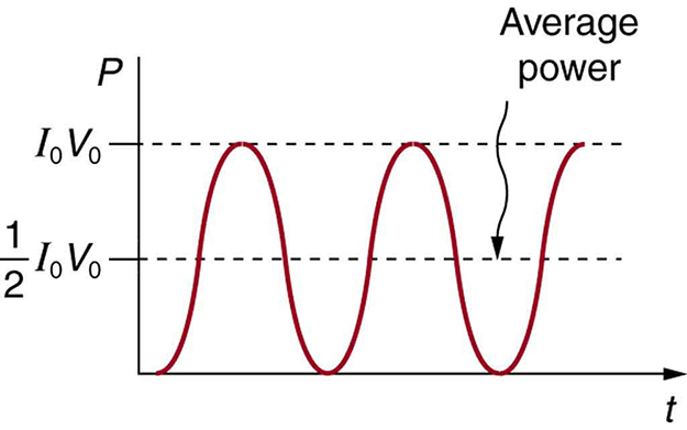
Average Power: AC power as a function of time. Since the voltage and current are in phase here, their product is non-negative and fluctuates between zero and I0V0. Average power is (1/2)I0V0.
\[\mathrm { P } _ { \mathrm { ave } } = \mathrm { I } _ { \mathrm { rms } } V _ { \mathrm { rms } } = \dfrac { \mathrm { I } _ { 0 } } { \sqrt { 2 } } \dfrac { \mathrm { V } _ { 0 } } { \sqrt { 2 } } = \dfrac { 1 } { 2 } \mathrm { V } _ { 0 } \mathrm { I } _ { 0 }\]
The RMS values are also useful if the voltage varies by some waveform other than sinusoids, such as with a square, triangular or sawtooth waves.
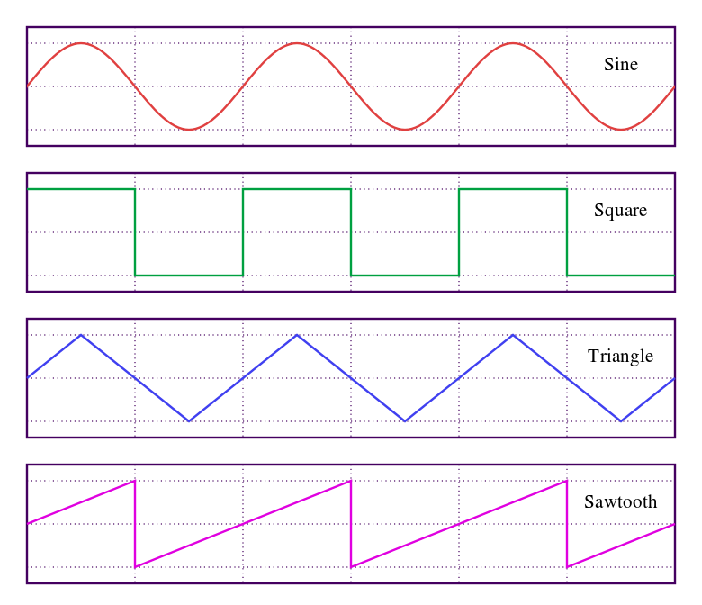
Waveforms: Sine, square, triangle, and sawtooth waveforms
Safety Precautions in the Household
Electrical safety systems and devices are designed and widely used to reduce the risks of thermal and shock hazards.
learning objectives
- Identify major risks associated with the electrical circuits and strategies to mitigate those risks
Electrical Safety and Household Appliances
Electricity has two hazards. A thermal hazard occurs in cases of electrical overheating. A shock hazard occurs when an electric current passes through a person. There are many systems and devices that prevent electrical hazards.
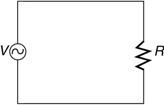
AC Circuit Lacking Safety Features: A schematic of a simple AC circuit with a voltage source and a single appliance represented by the resistance R. It lacks safety features.
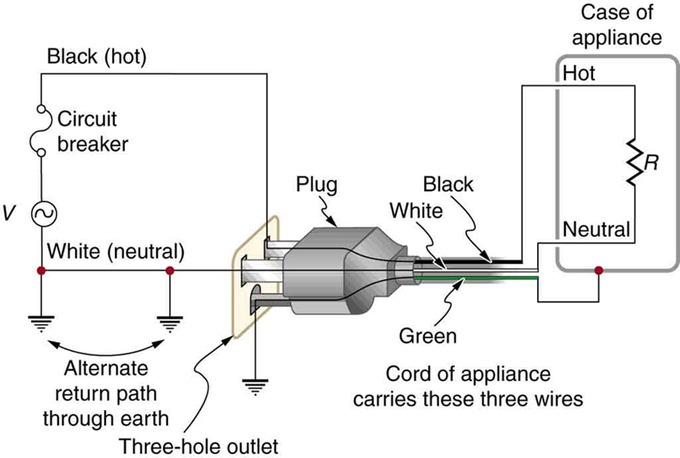
In practice, a simple AC circuit with no safety features is not how power is distributed. Modern household and industrial wiring requires the three-wire system, which has several safety features. The first safety feature is the familiar circuit breaker (or fuse) that prevents thermal overload. Secondly, there is a protective case around the appliance, as with a toaster or refrigerator. The case prevents people from touching exposed wires and coming into electrical contact with the circuit, helping prevent shocks.
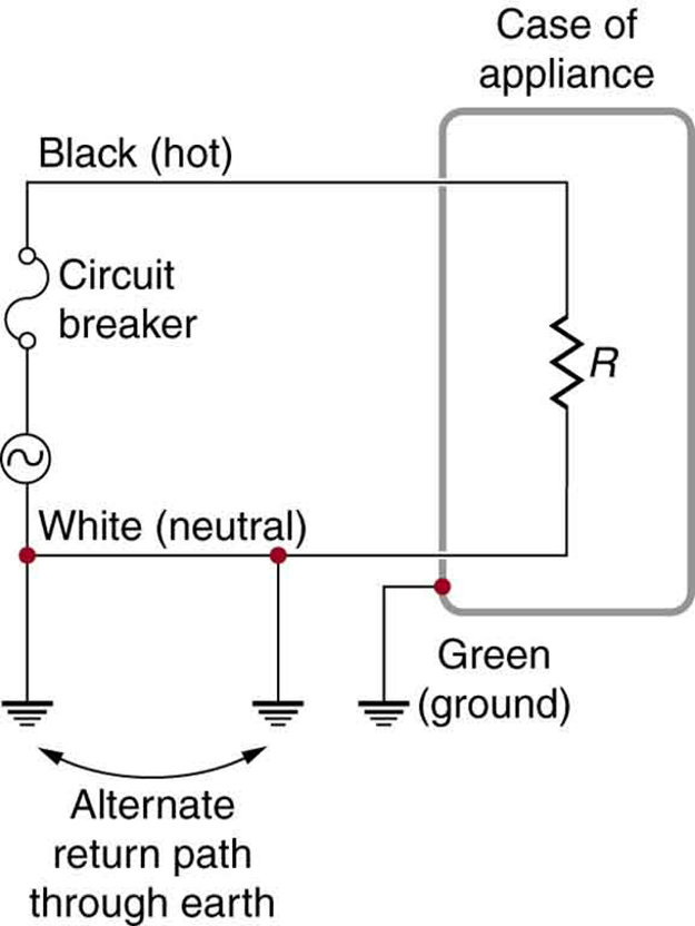
Three-Wire System: The three-wire system connects the neutral wire to the earth at the voltage source and the user location. It exists at zero volts and supplies an alternative return path for the current through the earth. The case of the appliance is also grounded to zero volts. A circuit breaker or fuse prevents thermal overload and exists in series on the active (live/hot) wire. Wire insulation colors vary by region. It is essential to check locally to determine which color codes are in use, even if they were followed in one particular installation.
There are three connections to the earth or ground (earth/ground, ). An earth/ground connection is a low-resistance path directly to the earth. The two earth/ground connections on the neutral wire force it to exist at zero volts relative to the earth, giving the wire its name. This wire is therefore safe to touch even if its insulation is missing. The neutral wire is the return path for the current to follow in order to complete the circuit.
The two earth/ground connections supply an alternative path through the earth to complete the circuit, since the earth is a good conductor. The earth/ground connection closest to the power source could be at the generating plant, while the other is situated at the user’s location. The third earth/ground connection involves the case of the appliance, through the green earth/ground wire, forcing the case to be at zero volts. The live or hot wire (live/hot) supplies the voltage and current to operate the appliance. The three-wire system is connected to an appliance through a three-prong plug.
Three-Prong Plug: The standard three-prong plug can only be inserted one way to ensure the proper function of the three-wire system.
The Three-Prong Plug
The three-wire system replaced the older two-wire system, which lacks an earth/ground wire. Under ordinary circumstances, insulation on the live/hot and neutral wires prevents the case from being situated directly within the circuit, so that the earth/ground wire may seem like double protection. Grounding the case solves more than one problem, however. The simplest problem is worn insulation on the live/hot wire that allows it to contact the case. When lacking an earth/ground connection (some people cut the third prong off the plug because they only have outdated two-hole receptacles), a severe shock is possible. This is particularly dangerous in the kitchen, where a good earth/ground connection is available through water on the floor or a water faucet.
With the earth/ground connection intact, the circuit breaker will trip, thus requiring appliance repair. Some appliances are still sold with two-prong plugs. These appliances, including power tools with impact resistant plastic cases, have nonconducting cases and are called ‘doubly insulated. ‘ Modern two-prong plugs can be inserted into the asymmetric standard outlet in only one way, ensuring the proper connection of live/hot and neutral wires.
Color-Coding
Insulating plastic is color-coded to identify live/hot, neutral, and ground wires, but these codes vary throughout the world. Live/hot wires may be brown, red, black, blue, or grey. Neutral wires may be blue, black, or white. Since the same color may be used for live/hot or neutral wires in different parts of the world, it is essential to confirm the color code for any given local region. The only exception is the earth/ground wire, which is often green but may be yellow or ‘bare wire. ‘ Striped coatings are sometimes used for the benefit of those who are colorblind.
Induction and Leakage Current
Electromagnetic induction causes a subtler problem solved by grounding the case. The alternating current in appliances can induce an EMF on the case. If grounded, the case voltage is kept near zero, but if the case is not grounded, a shock can occur. Current that is driven by the induced case EMF is called a leakage current, although current does not necessarily pass from the resistor to the case.
Key Points
- A phasor is a representation of a sinusoidal function whose amplitude (A), frequency (ω), and phase (θ) are time-invariant. If ω is shared by all components of the system, it can be factored out, leaving just A and ω. The term phasor usually refers to the last two factors.
- Phasors greatly reduce the complexity of expressing sinusoidally varying signals.
- Phasors may be used to analyze the behavior of electrical systems, such as RLC circuits, that have reached a kind of equilibrium called sinusoidal steady state. In the sinusoidal steady state, every voltage and current in a system is sinusoidal with angular frequency ω.
- Phasors allow us to apply techniques used to solve DC circuits to solve RC circuits.
- Recall that unlike DC current and voltage, which are constant, AC current and voltage vary over time. This is called alternating current because the direction alternates.
- The root mean square (abbreviated RMS or rms ) is a statistical measure of the magnitude of a varying quantity. We use the root mean square to express the average current or voltage in an AC system.
- The RMS current and voltage (for sinusoidal systems) are the peak current and voltage over the square root of two.
- The average power in an AC circuit is the product of the RMS current and RMS voltage.
- Electrical circuits carry the risks of overheating and potential electrical shocks.
- Fuses and circuit breakers are used to stop currents that exceed a set safety limit, thus preventing overheating.
- The three-wire system protects against thermal and shock hazards by using live, neutral, and ground wires, and grounding the neutral wire and the conducting cases of appliances.
- Before altering any circuitry, it is important to establish the correct color-coding scheme for your region (the color of live/hot, neutral, and ground wires).
- Alternating current has the potential to induce an EMF on the case of an appliance, which poses a shock hazard, so it is important to ground the case.
Key Terms
- sinusoidal steady state: Indicates every voltage and current in a system is sinusoidal with the same angular frequency ω.
- complex numbers: Numbers that have an imaginary part. Usually represented as i.
- phasor: A representation of a complex number in terms of a complex exponential.
- root mean square: The square root of the arithmetic mean of the squares.
- rms current: the root mean square of the current, \(\mathrm{I_{rms}=\frac{I_0}{\sqrt{2}}}\), where I0 is the peak current, in an AC system
- rms voltage: the root mean square of the voltage, \(\mathrm{V_{rms}=\frac{V_0}{\sqrt{2}}}\), where V0 is the peak voltage, in an AC system
- thermal hazard: an electrical hazard caused by overheating (e.g., in a resistive element)
- shock hazard: an electrical hazard that poses the risk of passing current through the body
- three-wire system: a modern wiring system with safety precautions; contains live, neutral, and ground wires
LICENSES AND ATTRIBUTIONS
CC LICENSED CONTENT, SHARED PREVIOUSLY
- Curation and Revision. Provided by: Boundless.com. License: CC BY-SA: Attribution-ShareAlike
CC LICENSED CONTENT, SPECIFIC ATTRIBUTION
- Bill Wilson, Review of Phasors. September 17, 2013. Provided by: OpenStax CNX. Located at: http://cnx.org/content/m11381/latest/. License: CC BY: Attribution
- Louis Scharf, Phasors: Phasor Representation of Signals. September 17, 2013. Provided by: OpenStax CNX. Located at: http://cnx.org/content/m21474/latest/. License: CC BY: Attribution
- Louis Scharf, Phasors: Sinusoidal Steady State and the Series RLC Circuit. September 17, 2013. Provided by: OpenStax CNX. Located at: http://cnx.org/content/m21475/latest/. License: CC BY: Attribution
- Phasor. Provided by: Wikipedia. Located at: en.Wikipedia.org/wiki/Phasor. License: CC BY-SA: Attribution-ShareAlike
- phasor. Provided by: Wiktionary. Located at: en.wiktionary.org/wiki/phasor. License: CC BY-SA: Attribution-ShareAlike
- sinusoidal steady state. Provided by: Wikipedia. Located at: en.Wikipedia.org/wiki/sinusoidal%20steady%20state. License: CC BY-SA: Attribution-ShareAlike
- complex numbers. Provided by: Wiktionary. Located at: en.wiktionary.org/wiki/complex_numbers. License: CC BY-SA: Attribution-ShareAlike
- Louis Scharf, Phasors: Phasor Representation of Signals. October 26, 2012. Provided by: OpenStax CNX. Located at: http://cnx.org/content/m21474/latest/. License: CC BY: Attribution
- Phasor. Provided by: Wikipedia. Located at: en.Wikipedia.org/wiki/Phasor. License: Public Domain: No Known Copyright
- Louis Scharf, Phasors: Sinusoidal Steady State and the Series RLC Circuit. October 26, 2012. Provided by: OpenStax CNX. Located at: http://cnx.org/content/m21475/latest/. License: CC BY: Attribution
- OpenStax College, College Physics. September 18, 2013. Provided by: OpenStax CNX. Located at: http://cnx.org/content/m42348/latest/?collection=col11406/1.7. License: CC BY: Attribution
- Root mean square. Provided by: Wikipedia. Located at: en.Wikipedia.org/wiki/Root_mean_square. License: CC BY-SA: Attribution-ShareAlike
- Boundless. Provided by: Boundless Learning. Located at: www.boundless.com//physics/definition/rms-voltage. License: CC BY-SA: Attribution-ShareAlike
- Boundless. Provided by: Boundless Learning. Located at: www.boundless.com//physics/definition/rms-current. License: CC BY-SA: Attribution-ShareAlike
- root mean square. Provided by: Wiktionary. Located at: en.wiktionary.org/wiki/root_mean_square. License: CC BY-SA: Attribution-ShareAlike
- Louis Scharf, Phasors: Phasor Representation of Signals. October 26, 2012. Provided by: OpenStax CNX. Located at: http://cnx.org/content/m21474/latest/. License: CC BY: Attribution
- Phasor. Provided by: Wikipedia. Located at: en.Wikipedia.org/wiki/Phasor. License: Public Domain: No Known Copyright
- Louis Scharf, Phasors: Sinusoidal Steady State and the Series RLC Circuit. October 26, 2012. Provided by: OpenStax CNX. Located at: http://cnx.org/content/m21475/latest/. License: CC BY: Attribution
- OpenStax College, College Physics. October 29, 2012. Provided by: OpenStax CNX. Located at: http://cnx.org/content/m42348/latest/?collection=col11406/1.7. License: CC BY: Attribution
- Root mean square. Provided by: Wikipedia. Located at: en.Wikipedia.org/wiki/Root_mean_square. License: Public Domain: No Known Copyright
- OpenStax College, College Physics. October 29, 2012. Provided by: OpenStax CNX. Located at: http://cnx.org/content/m42348/latest/?collection=col11406/1.7. License: CC BY: Attribution
- Boundless. Provided by: Boundless Learning. Located at: www.boundless.com//physics/definition/thermal-hazard. License: CC BY-SA: Attribution-ShareAlike
- OpenStax College, College Physics. September 17, 2013. Provided by: OpenStax CNX. Located at: http://cnx.org/content/m42416/latest/?collection=col11406/1.7. License: CC BY: Attribution
- Boundless. Provided by: Boundless Learning. Located at: www.boundless.com//physics/definition/three-wire-system. License: CC BY-SA: Attribution-ShareAlike
- Boundless. Provided by: Boundless Learning. Located at: www.boundless.com//physics/definition/shock-hazard. License: CC BY-SA: Attribution-ShareAlike
- Louis Scharf, Phasors: Phasor Representation of Signals. October 26, 2012. Provided by: OpenStax CNX. Located at: http://cnx.org/content/m21474/latest/. License: CC BY: Attribution
- Phasor. Provided by: Wikipedia. Located at: http://en.Wikipedia.org/wiki/Phasor. License: Public Domain: No Known Copyright
- Louis Scharf, Phasors: Sinusoidal Steady State and the Series RLC Circuit. October 26, 2012. Provided by: OpenStax CNX. Located at: http://cnx.org/content/m21475/latest/. License: CC BY: Attribution
- OpenStax College, College Physics. October 29, 2012. Provided by: OpenStax CNX. Located at: http://cnx.org/content/m42348/latest/?collection=col11406/1.7. License: CC BY: Attribution
- Root mean square. Provided by: Wikipedia. Located at: en.Wikipedia.org/wiki/Root_mean_square. License: Public Domain: No Known Copyright
- OpenStax College, College Physics. October 29, 2012. Provided by: OpenStax CNX. Located at: http://cnx.org/content/m42348/latest/?collection=col11406/1.7. License: CC BY: Attribution
- OpenStax College, College Physics. October 30, 2012. Provided by: OpenStax CNX. Located at: http://cnx.org/content/m42416/latest/?collection=col11406/1.7. License: CC BY: Attribution
- OpenStax College, College Physics. October 30, 2012. Provided by: OpenStax CNX. Located at: http://cnx.org/content/m42416/latest/?collection=col11406/1.7. License: CC BY: Attribution
- OpenStax College, College Physics. October 30, 2012. Provided by: OpenStax CNX. Located at: http://cnx.org/content/m42416/latest/?collection=col11406/1.7. License: CC BY: Attribution


