
4.3: Conservation Laws
- Page ID
- 29889

\( \newcommand{\vecs}[1]{\overset { \scriptstyle \rightharpoonup} {\mathbf{#1}} } \)
\( \newcommand{\vecd}[1]{\overset{-\!-\!\rightharpoonup}{\vphantom{a}\smash {#1}}} \)
\( \newcommand{\dsum}{\displaystyle\sum\limits} \)
\( \newcommand{\dint}{\displaystyle\int\limits} \)
\( \newcommand{\dlim}{\displaystyle\lim\limits} \)
\( \newcommand{\id}{\mathrm{id}}\) \( \newcommand{\Span}{\mathrm{span}}\)
( \newcommand{\kernel}{\mathrm{null}\,}\) \( \newcommand{\range}{\mathrm{range}\,}\)
\( \newcommand{\RealPart}{\mathrm{Re}}\) \( \newcommand{\ImaginaryPart}{\mathrm{Im}}\)
\( \newcommand{\Argument}{\mathrm{Arg}}\) \( \newcommand{\norm}[1]{\| #1 \|}\)
\( \newcommand{\inner}[2]{\langle #1, #2 \rangle}\)
\( \newcommand{\Span}{\mathrm{span}}\)
\( \newcommand{\id}{\mathrm{id}}\)
\( \newcommand{\Span}{\mathrm{span}}\)
\( \newcommand{\kernel}{\mathrm{null}\,}\)
\( \newcommand{\range}{\mathrm{range}\,}\)
\( \newcommand{\RealPart}{\mathrm{Re}}\)
\( \newcommand{\ImaginaryPart}{\mathrm{Im}}\)
\( \newcommand{\Argument}{\mathrm{Arg}}\)
\( \newcommand{\norm}[1]{\| #1 \|}\)
\( \newcommand{\inner}[2]{\langle #1, #2 \rangle}\)
\( \newcommand{\Span}{\mathrm{span}}\) \( \newcommand{\AA}{\unicode[.8,0]{x212B}}\)
\( \newcommand{\vectorA}[1]{\vec{#1}} % arrow\)
\( \newcommand{\vectorAt}[1]{\vec{\text{#1}}} % arrow\)
\( \newcommand{\vectorB}[1]{\overset { \scriptstyle \rightharpoonup} {\mathbf{#1}} } \)
\( \newcommand{\vectorC}[1]{\textbf{#1}} \)
\( \newcommand{\vectorD}[1]{\overrightarrow{#1}} \)
\( \newcommand{\vectorDt}[1]{\overrightarrow{\text{#1}}} \)
\( \newcommand{\vectE}[1]{\overset{-\!-\!\rightharpoonup}{\vphantom{a}\smash{\mathbf {#1}}}} \)
\( \newcommand{\vecs}[1]{\overset { \scriptstyle \rightharpoonup} {\mathbf{#1}} } \)
\(\newcommand{\longvect}{\overrightarrow}\)
\( \newcommand{\vecd}[1]{\overset{-\!-\!\rightharpoonup}{\vphantom{a}\smash {#1}}} \)
\(\newcommand{\avec}{\mathbf a}\) \(\newcommand{\bvec}{\mathbf b}\) \(\newcommand{\cvec}{\mathbf c}\) \(\newcommand{\dvec}{\mathbf d}\) \(\newcommand{\dtil}{\widetilde{\mathbf d}}\) \(\newcommand{\evec}{\mathbf e}\) \(\newcommand{\fvec}{\mathbf f}\) \(\newcommand{\nvec}{\mathbf n}\) \(\newcommand{\pvec}{\mathbf p}\) \(\newcommand{\qvec}{\mathbf q}\) \(\newcommand{\svec}{\mathbf s}\) \(\newcommand{\tvec}{\mathbf t}\) \(\newcommand{\uvec}{\mathbf u}\) \(\newcommand{\vvec}{\mathbf v}\) \(\newcommand{\wvec}{\mathbf w}\) \(\newcommand{\xvec}{\mathbf x}\) \(\newcommand{\yvec}{\mathbf y}\) \(\newcommand{\zvec}{\mathbf z}\) \(\newcommand{\rvec}{\mathbf r}\) \(\newcommand{\mvec}{\mathbf m}\) \(\newcommand{\zerovec}{\mathbf 0}\) \(\newcommand{\onevec}{\mathbf 1}\) \(\newcommand{\real}{\mathbb R}\) \(\newcommand{\twovec}[2]{\left[\begin{array}{r}#1 \\ #2 \end{array}\right]}\) \(\newcommand{\ctwovec}[2]{\left[\begin{array}{c}#1 \\ #2 \end{array}\right]}\) \(\newcommand{\threevec}[3]{\left[\begin{array}{r}#1 \\ #2 \\ #3 \end{array}\right]}\) \(\newcommand{\cthreevec}[3]{\left[\begin{array}{c}#1 \\ #2 \\ #3 \end{array}\right]}\) \(\newcommand{\fourvec}[4]{\left[\begin{array}{r}#1 \\ #2 \\ #3 \\ #4 \end{array}\right]}\) \(\newcommand{\cfourvec}[4]{\left[\begin{array}{c}#1 \\ #2 \\ #3 \\ #4 \end{array}\right]}\) \(\newcommand{\fivevec}[5]{\left[\begin{array}{r}#1 \\ #2 \\ #3 \\ #4 \\ #5 \\ \end{array}\right]}\) \(\newcommand{\cfivevec}[5]{\left[\begin{array}{c}#1 \\ #2 \\ #3 \\ #4 \\ #5 \\ \end{array}\right]}\) \(\newcommand{\mattwo}[4]{\left[\begin{array}{rr}#1 \amp #2 \\ #3 \amp #4 \\ \end{array}\right]}\) \(\newcommand{\laspan}[1]{\text{Span}\{#1\}}\) \(\newcommand{\bcal}{\cal B}\) \(\newcommand{\ccal}{\cal C}\) \(\newcommand{\scal}{\cal S}\) \(\newcommand{\wcal}{\cal W}\) \(\newcommand{\ecal}{\cal E}\) \(\newcommand{\coords}[2]{\left\{#1\right\}_{#2}}\) \(\newcommand{\gray}[1]{\color{gray}{#1}}\) \(\newcommand{\lgray}[1]{\color{lightgray}{#1}}\) \(\newcommand{\rank}{\operatorname{rank}}\) \(\newcommand{\row}{\text{Row}}\) \(\newcommand{\col}{\text{Col}}\) \(\renewcommand{\row}{\text{Row}}\) \(\newcommand{\nul}{\text{Nul}}\) \(\newcommand{\var}{\text{Var}}\) \(\newcommand{\corr}{\text{corr}}\) \(\newcommand{\len}[1]{\left|#1\right|}\) \(\newcommand{\bbar}{\overline{\bvec}}\) \(\newcommand{\bhat}{\widehat{\bvec}}\) \(\newcommand{\bperp}{\bvec^\perp}\) \(\newcommand{\xhat}{\widehat{\xvec}}\) \(\newcommand{\vhat}{\widehat{\vvec}}\) \(\newcommand{\uhat}{\widehat{\uvec}}\) \(\newcommand{\what}{\widehat{\wvec}}\) \(\newcommand{\Sighat}{\widehat{\Sigma}}\) \(\newcommand{\lt}{<}\) \(\newcommand{\gt}{>}\) \(\newcommand{\amp}{&}\) \(\definecolor{fillinmathshade}{gray}{0.9}\)Conservation Laws
Concepts and Principles
The Angular Impulse-Angular Momentum Relation
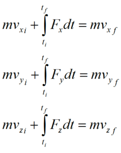
We’ve already used the impulse-momentum relation to analyze situations involving translations through three-dimensional space. The relation is typically applied in its component form:
Arguing by analogy, if the change in momentum in the x-, y-, and z-directions is equal to the impulse applied to the object in each direction doesn’t it seem plausible that a similar relation would hold in the “q-direction”? If so, this relation should be constructed between the torques acting on an object, the time interval over which the torques act, and the change in angular velocity of an object.[1] The relation should be:

The product of rotational inertia and angular velocity is termed the angular momentum of the object, typically denoted L, and the product of torque and the time interval over which it acts is termed the angular impulse applied to the object.
Thus, if no angular impulse is applied to an object, its angular momentum will remain constant. This special case is referred to as angular momentum conservation. However, if an angular impulse is applied to the object, the angular momentum will change by an amount exactly equal to the angular impulse applied. Angular momentum is changed through angular impulse.
Incorporating Rotation in the Work-Energy Relation
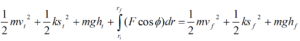
Our previous encounter with the work-energy relation resulted in:
Recall from our previous discussion of work-energy that this is not a vector equation, meaning it is not applied independently in each of the coordinate directions. Generalizing this equation to include rotation will involving adding terms to this equation, not creating a separate “angular” energy equation.
Recall that we model the motion of an arbitrary rigid body as a superposition of a pure translation of the CM and a pure rotation about the CM. Let’s investigate the effect of this model on our calculation of the kinetic energy of the object.
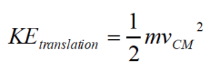
The translation portion of the motion is easy. We envision the object as a point particle, localized at the CM of the real object, traveling with the velocity of the CM of the object. Thus, this portion of the motion contributes a kinetic energy,
What about the kinetic energy due to the pure rotation of the object about the axis through the CM?
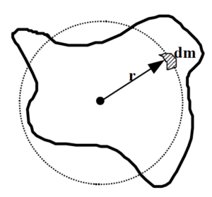 | Every small chunk of the object, dm, moves in a circle around the CM. Each of these pieces of mass has a velocity magnitude given by Thus, the kinetic energy of each piece is
|
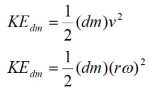
Therefore, the total kinetic energy due to rotation of all the little pieces is:

Combining the kinetic energy due to rotation with the kinetic energy due to translation leads to a total kinetic energy of:
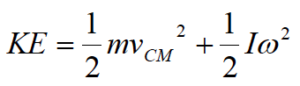
and a work-energy relation of:
Unless a scenario involves springs or other elastic material, I’ll typically write this relationship as:
Analysis Tools
Applying the Work-Energy Relation including Rotation – I
A mischievous child releases his mother’s bowling ball from the top of the family’s 25 m long, 150 above horizontal driveway. The ball rolls without slipping down the driveway and at the bottom plows into the mailbox. The 6.4 kg ball has a diameter of 24 cm.
Let’s determine the speed of the ball when it hits the mailbox. To determine this value, we can apply the work-energy relation to the ball between:
Event 1: The instant the ball is released.
Event 2: The instant the ball hits the mailbox.
For these two events, work-energy looks like this:
 | 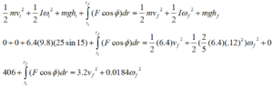 where the bottom of the driveway is the zero for gravitational potential energy and the rotational inertia of the bowling ball is taken to be that of a sphere. |
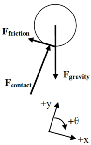
Now we must carefully determine which, if any, of the forces on the bowling ball do work on the bowling ball.
First, we don’t have to worry about the force of gravity. The gravitational potential energy function was developed to automatically incorporate the work done by the force of gravity.
Second, the contact force can do no work on the ball because the contact force is always perpendicular to the motion of the ball.
Finally, what about the force of friction? It does appear, at first glance, that the force of friction is applied over the entire motion of the ball down the driveway. However, let’s pay closer attention to the actual point at which the force acts.
The frictional force is static in nature, because since the ball rolls without slipping down the driveway the bottom of the ball is always in static contact with the ground (i.e., there is no relative velocity between the bottom of the ball and the ground). If the bottom of the ball has a velocity of zero, then the force that acts on the bottom of the ball (static friction) can act through no distance. During the instant at which the frictional force acts on a particular point on the bottom of the ball, that point is not moving. That point on the ball only moves when it is no longer in contact with the ground, but by that time the frictional force is acting on a different point. To summarize (and stop saying the same thing over and over), the force of static friction can do no work because it acts on a point that does not move.
Thus, our equation simplifies to:
The linear and angular velocity of the ball must be related. Since the ball rolls without slipping, the bottom of the ball has no linear velocity. Since the velocity of the bottom of the ball is the sum of the velocity due to translation of the CM and the velocity due to rotation about the CM, the velocity due to rotation must be equal in magnitude to the velocity of the CM:

Substituting this into our equation yields:
Applying the Work-Energy Relation including Rotation – II
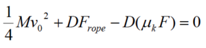
The crate is descending with speed v0 when a brake shoe is applied to the disk-shaped pulley of mass M and radius R. The coefficient of friction between the shoe and the pulley is (ms, mk). Determine the distance (D) the crate moves before stopping as a function of M, m, F, R, v0, g, and the appropriate coefficient of friction. | 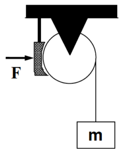 |
To determine this function, let’s apply the work-energy relation to both the crate and the pulley between:
Event 1: The instant the brake shoe is applied.
Event 2: The instant the crate comes to rest.
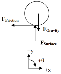
In addition to defining the two instants of interest, we’ll need free-body diagrams for both the crate and the pulley.
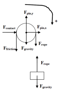 | 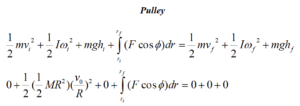 To find the work on the pulley, note that Fcontact and Fpin do no work since the distance over which these forces act is zero. However, both Frope and Ffriction do work. If the crate falls a distance D, both of these forces act over a distance D. However, note that this displacement is in the same direction as Frope (f = 0) on the right side of the pulley but in the opposite direction on the other side of the pulley (opposite to Ffriction and therefore f = 180.) Since these forces are constant, there’s no need to actually integrate: 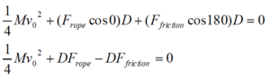 Note that since the brake shoe does not accelerate, the external force applied to the shoe, F, is the same magnitude as the contact force between the shoe and the pulley.
|
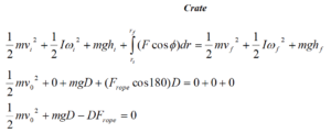
where the final position of the crate is the zero for gravitational potential energy.
The two equations can be added together to yield:
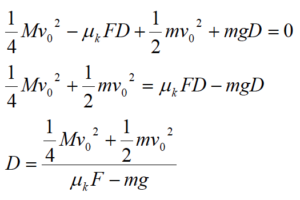
Thus, in order for D to have a physical (positive) value, the frictional force on the pulley must be greater in magnitude than the force of gravity on the crate, which agrees with common sense. Note that the numerator is simply the total kinetic energy of the pulley plus crate. The larger this sum, the larger the distance needed to stop the crate’s fall, which again agrees with common sense.
Applying the Impulse-Momentum Relations (Linear and Angular) – I
A bowling ball of mass M and radius R leaves a bowler’s hand with CM velocity v0 and no rotation. The ball skids down the alley before it begins to roll without slipping. The coefficient of friction is (ms, mk). Determine the elapsed time (T) before the ball begins to roll without slipping as a function of M, R, v0, g, and the appropriate coefficient of friction.
To determine this function, let’s apply the impulse-momentum relations to the ball between:
Event 1: The instant the ball leaves the bowler’s hand.
Event 2: The instant the ball begins to roll without slipping.
 | Since the ball both translates and rotates, we must write both the linear and rotational forms of the impulse-momentum relation. Remember, the rotation of the bowling ball is modeled to be about an axis through the CM. (Since all the forces are constant, we’ll write the relations without the use of the integral.) |
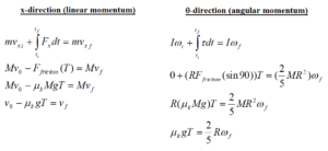
The final CM velocity and final angular velocity are related because at this instant the ball begins to roll without slipping. When the ball rolls without slipping, the bottom of the ball is in static contact with the ground, i.e., it has no linear velocity. Since the velocity of the bottom of the ball is the sum of the velocity due to translation of the CM and the velocity due to rotation about the CM, the velocity due to rotation must be equal in magnitude to the velocity of the CM:
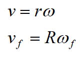
Substituting this into our angular equation yields:
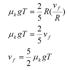
Plugging this into the linear equation:

Thus, the faster you throw the ball, or the smaller the kinetic coefficient of friction, the longer it will take for the ball to begin to roll.
Applying the Impulse-Momentum Relations (Linear and Angular) – II
A 30 kg child running at 4.0 m/s leaps onto the outer edge of an initially stationary merry-go-round. The merry-go-round is a flat disk of radius 2.4 m and mass 70 kg. Ignore the frictional torque in the bearings of the merry-go-round.
Let’s imagine we’re interested in determining the final angular velocity of the merry-go-round after the child has safely come to rest on its surface. To determine this angular velocity, we can apply the impulse-momentum relations to both the child and the merry-go-round between:
Event 1: The instant before the child lands on the merry-go-round
Event 2: The instant after the child comes to rest on the merry-go-round.
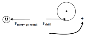
The child and the merry-go-round interact via some unknown magnitude force. (Contrary to the free-body diagram, this force does not necessarily act on the child’s disembodied head.) There are also other forces due to gravity and supporting structures that act on both the child and the merry-go-round, however, these forces are in the vertical direction and supply no torque.
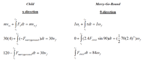
The final velocity of the child and final angular velocity of the merry-go-round are related because at this instant the child is at rest (hanging on to) the merry-go-round. Therefore,
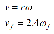
Substituting this into our angular equation yields:

By Newton’s Third Law, the force of the child on the merry-go-round and the force of the merry-go-round on the child must be equal in magnitude. Therefore our two equations can be summed and the impulses cancel. This gives:
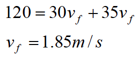
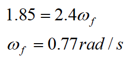
The child is slowed from 4 m/s to 1.85 m/s by jumping onto the merry-go-round. The merry-go-round, however, is accelerated from rest to:
Activities
For each of the scenarios described below, indicate the amount of linear kinetic energy, rotational kinetic energy, and gravitational potential energy in the system at each of the events listed. Use a consistent scale for each motion. Set the lowest point of each motion as the zero-point of gravitational potential energy.
A mischievous child releases his mother’s bowling ball from the top of the family’s 15 m long, 80 above horizontal driveway. The ball rolls without slipping down the driveway and at the bottom plows into the mailbox.
A yo-yo of inner diameter 0.70 cm and outer diameter 8.0 cm is released from rest. The string is 0.80 m long. Assume the string does not slip on the inner diameter of the yo-yo as the yo-yo falls..
For each of the scenarios described below, indicate the amount of linear kinetic energy, rotational kinetic energy, and gravitational potential energy of each object at each of the events listed. Use a consistent scale for each motion. Set the initial positions of the objects as the zero-points of gravitational potential energy.
Tired of walking up the stairs, an 80 kg engineering student (S) designs an ingenious device for reaching his third floor dorm room. An 84 kg block (B) is attached to a rope that passes over a 0.70 m diameter, 15 kg, disk-shaped pulley (P). The student holds the other end of the rope. When the block is released, the student is pulled up to his dorm room.
A 75 kg man (M) is falling at 20 m/s, 75 m above crocodile infested waters! He holds a rope attached to a 15 kg simple pulley (P). In an attempt to save him, a brake shoe is pressed against the spinning pulley. The man is saved, but barely.
For each of the scenarios described below, indicate the amount of linear kinetic energy, rotational kinetic energy, and gravitational potential energy of each object at each of the events listed. Use a consistent scale throughout both motions. Set the initial positions of the objects as the zero-points of gravitational potential energy
In a horizontal skiing device, the skier begins from rest 35 m from the end of the skiing run. The skier (S) has a mass of 75 kg, the block (B) has a mass of 50 kg, and the simple pulley (P) has a mass of 15 kg. The coefficient of friction is extremely small.
In an inclined skiing device, the skier begins from rest 35 m from the end of the 200 above horizontal inclined skiing run. The skier (S) has a mass of 75 kg, the block (B) has a mass of 50 kg, and the simple pulley (P) has a mass of 15 kg. The coefficient of friction is extremely small.
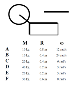
A disk-shaped pulley of mass M and radius R is rotating at angular velocity w. The friction in its bearings is so small that it can be ignored. A brake shoe is pressed against the pulley in order to stop it. In all cases, the brake shoe is pressed against the pulley with the same force and the coefficient of friction between the brake shoe and the pulley is the same.
Rank the scenarios below on the amount of time it takes to stop the pulley.
Largest 1. _____ 2. _____ 3. _____ 4. _____ 5. _____ 6. _____ Smallest
_____ The ranking cannot be determined based on the information provided.
Explain the reason for your ranking:
Rank the scenarios below on the angle through which the pulley rotates before stopping.
Largest 1. _____ 2. _____ 3. _____ 4. _____ 5. _____ 6. _____ Smallest
_____ The ranking cannot be determined based on the information provided.
Explain the reason for your ranking:
A disk-shaped pulley of mass M and radius R is rotating at angular velocity w. The friction in its bearings is constant and ultimately causes the pulley to stop rotating.

Rank the scenarios below on the amount of time it takes to stop the pulley.
Largest 1. _____ 2. _____ 3. _____ 4. _____ 5. _____ 6. _____ Smallest
_____ The ranking cannot be determined based on the information provided.
Explain the reason for your ranking:
Rank the scenarios below on the angle through which the pulley rotates before stopping.
Largest 1. _____ 2. _____ 3. _____ 4. _____ 5. _____ 6. _____ Smallest
_____ The ranking cannot be determined based on the information provided.
Explain the reason for your ranking:
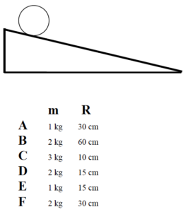
A sphere of mass m and radius R is released from rest at the top of an incline and rolls without slipping down the incline. All spheres are released from rest from the same location on the incline.
Rank the speed of the sphere at the bottom of the incline.
Largest 1. _____ 2. _____ 3. _____ 4. _____ 5. _____ 6. _____ Smallest
_____ The ranking cannot be determined based on the information provided.
Explain the reason for your ranking:
Six different equal-mass objects are released from rest from the same location at the top of an incline and roll without slipping down the incline.
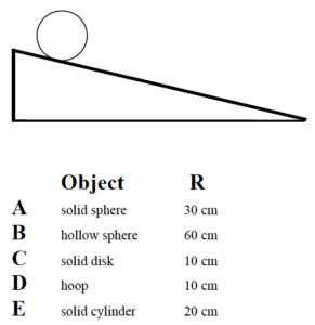
Rank the speed of the objects at the bottom of the incline.
Largest 1. _____ 2. _____ 3. _____ 4. _____ 5. _____ Smallest
_____ The ranking cannot be determined based on the information provided.
Explain the reason for your ranking:
A merry-go-round of radius R is rotating at constant angular speed. The friction in its bearings is so small that it can be ignored. A sandbag of mass m is dropped onto the merry-go-round, at a position designated by r. The sandbag does not slip or roll upon contact with the merry-go-round.

Rank the scenarios on the basis of the angular speed of the merry-go-round after the sandbag “sticks” to the merry-go-round.
Largest 1. _____ 2. _____ 3. _____ 4. _____ 5. _____ 6. _____ Smallest
_____ The ranking cannot be determined based on the information provided.
Explain the reason for your ranking:
| The 75 kg man is falling at 20 m/s, 75 m above the crocodile infested waters below! In an attempt to save him, the brake shoe is pressed against the spinning pulley. The coefficient of friction between the brake shoe and the pulley is (0.9, 0.8), and the 35 kg disk-shaped pulley has inner and outer diameters of 0.60 m and 0.90 m, respectively. The man is saved, but barely. | 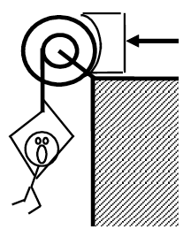 |
Free-Body Diagrams Mathematical Analysis[i]
| Event 1: Event 2:
|
| The 75 kg man is falling at 15 m/s! In an attempt to stop his fall, the brake shoe is pressed against the spinning pulley with a force of 1000 N. The coefficient of friction between the brake shoe and the pulley is (0.9, 0.8), and the 35 kg disk-shaped pulley has inner and outer diameters of 0.60 m and 0.90 m, respectively.
| 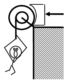 |
Free-Body Diagrams Mathematical Analysis[ii]
| Event 1: Event 2:
|
How long does it take to stop the man’s fall?
How far does the man fall?
Tired of walking up the stairs, an 80 kg engineering student designs an ingenious device for reaching his third floor dorm room. An 84 kg block is attached to a rope that passes over a 0.70 m diameter, 15 kg, disk-shaped pulley. The student holds the other end of the rope. When the 84 kg block is released, the student is pulled up to his dorm room in 5.3 s.
Free-Body Diagrams Mathematical Analysis[iii]
| Event 1: Event 2:
|
Tired of walking up the stairs, an 80 kg engineering student designs an ingenious device for reaching her third floor dorm room. An 42 kg block is attached to a rope that passes over the outer diameter of a 0.70 m outer diameter, 15 kg, disk-shaped compound pulley. The student holds a second rope, wrapped around the inner 0.35 m diameter of the pulley. When the 42 kg block is released, the student is pulled up to her dorm room, 8.0 m off the ground.
Free-Body Diagrams Mathematical Analysis[iv]
| Event 1: Event 2:
|
| A 60 kg student lifts herself from rest to a speed of 1.5 m/s in 2.1 s. The boson’s chair has a mass of 35 kg. The 20 kg, disk-shaped pulley has a diameter of 1.1 m. | 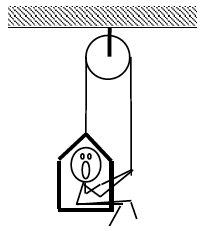 |
Free-Body Diagrams Mathematical Analysis[v]
| Event 1: Event 2:
|
| The device at right guarantees all the excitement of skiing without the need for hills. The 80 kg man begins from rest and reaches a speed of 34 m/s in 7.2 s. The 10 kg, disk-shaped pulley has inner and outer diameters of 0.40 m and 0.90 m, respectively. Assume friction is so small that it can be ignored. | 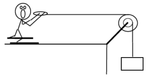 |
Free-Body Diagrams Mathematical Analysis[vi]
| Event 1: Event 2:
|
| The device at right allows you to ski uphill. The 85 kg skier begins from rest and reaches a speed of 14 m/s after traveling 25 m up the incline. The 10 kg, disk-shaped pulley has diameter 0.90 m. Assume friction is so small that it can be ignored. The ramp is inclined at 20° above horizontal. | 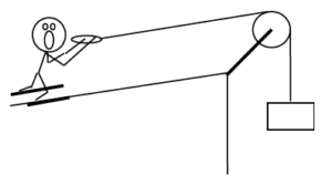 |
Free-Body Diagrams Mathematical Analysis[vii]
| Event 1: Event 2:
|
A yo-yo of mass 0.60 kg, inner diameter 0.70 cm, and outer diameter 8.0 cm is released from rest. The string is 0.80 m long. Assume the rotational inertia of the yo-yo is similar to a simple disk and that the unwinding of the string does not affect the rotational inertia.
Free-Body Diagram Mathematical Analysis[viii]
| Event 1: Event 2:
|
A bowling ball of mass 7.1 kg and diameter 21.6 cm is thrown down the alley at a speed of 9.5 m/s. The bowling ball is initially skidding, with no angular velocity, down the alley. The ball skids for 1.8 s before it begins to roll without slipping.
Free-Body Diagram Mathematical Analysis[ix]
| Event 1: Event 2:
|
A mischievous child releases his mother’s bowling ball from the top of the family’s 15 m long, 80 above horizontal driveway. The ball rolls without slipping down the driveway and at the bottom plows into the mailbox. The 6.4 kg ball has a diameter of 21.6 cm.
Free-Body Diagram Mathematical Analysis[x]
| Event 1: Event 2:
|
| The 65 kg strange man at right is trapped inside a section of large pipe. If that’s not bad enough, the pipe begins to roll from rest down a 35 m long, 180 incline! The pipe rolls down the hill without slipping. The pipe has a mass of 180 kg and a diameter of 1.2 m. (Assume the man’s presence inside the pipe has a negligible effect on the pipe’s rotational inertia.) | 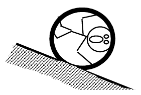 |
Free-Body Diagram Mathematical Analysis[xi]
| Event 1: Event 2:
|
A 30 kg child running at 3.0 m/s leaps onto the outer edge of an initially stationary merry-go-round. The merry-go-round is a flat disk of radius 2.4 m and mass 50 kg. Ignore the frictional torque in the bearings of the merry-go-round.
Free-Body Diagrams Mathematical Analysis[xii]
| child (top view)
| merry-go-round (top view)
| Event 1: Event 2: |
A 40 kg child running at 4.0 m/s leaps onto the outer edge of a merry-go-round initially rotating in the opposite direction. The merry-go-round is brought to rest. The merry-go-round is a flat disk of radius 2.4 m and mass 50 kg. Ignore the frictional torque in the bearings of the merry-go-round.
Free-Body Diagrams Mathematical Analysis[xiii]
| child (top view)
| merry-go-round (top view)
| Event 1: Event 2: |
A 30 kg bag of sand is dropped onto a merry-go-round 1.6 m from its center. The merry-go-round was rotating at 3.2 rad/s before the bag was dropped. The merry-go-round is a flat disk of radius 2.4 m and mass 50 kg. Ignore the frictional torque in the bearings of the merry-go-round.
Free-Body Diagrams Mathematical Analysis[xiv]
| sandbag (top view)
| merry-go-round (top view)
| Event 1: Event 2: |
A 30 kg bag of sand is dropped onto a merry-go-round. The merry-go-round was rotating at 2.2 rad/s before the bag was dropped, and 1.3 rad/s after the bag comes to rest. The merry-go-round is a flat disk of radius 2.4 m and mass 60 kg. Ignore the frictional torque in the bearings of the merry-go-round.
Free-Body Diagrams Mathematical Analysis[xv]
| sandbag (top view)
| merry-go-round (top view)
| Event 1: Event 2: |
A child leaps onto the outer edge of an initially stationary merry-go-round. The merry-go-round is a flat disk of radius R and mass M. Determine the angular speed of the merry-go-round ( w) after the child jumps on as a function of the child’s mass (m), initial speed (v), M, and R. Ignore the frictional torque in the bearings of the merry-go-round.
Free-Body Diagrams Mathematical Analysis
| child (top view)
| merry-go-round (top view)
| Event 1: Event 2: |
Questions
If v = 0 m/s, what should w equal? Does your function agree with this observation?
If M =∞, what should w equal? Does your function agree with this observation?
If m =∞, what should w equal? Does your function agree with this observation?
Tired of walking up the stairs, an engineering student of mass m designs an ingenious device for reaching her third floor dorm room. An block of mass M is attached to a rope that passes over a disk-shaped pulley of mass Mp and radius R. The student holds the other end of the rope. When the block is released, the student is pulled up to her dorm room. Determine the velocity of the student (vS) as she reaches her room as a function of m, M, Mp, R, g, and her distance off the ground (D).
Free-Body Diagrams Mathematical Analysis
| Event 1: Event 2:
|
Questions
If D = 0 m, what should vS equal? Does your function agree with this observation?
If m = M, what should vS equal? Does your function agree with this observation?
If Mp= ∞, what should vS equal? Does your function agree with this observation?
| The man of mass m is falling at speed v! In an attempt to save him, the brake shoe is pressed against the spinning pulley with force F. The pulley has mass M and radius R. Determine the time needed to stop the man’s fall (T) as a function of m, M, v, R, g, F, and the appropriate coefficient of friction between the brake shoe and the pulley. | 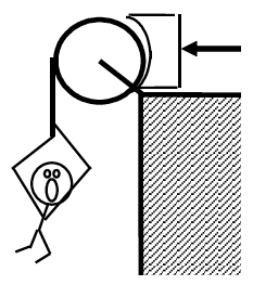 |
Free-Body Diagrams Mathematical Analysis
| Event 1: Event 2:
|
Questions
If m = 0, what should T equal? Does your function agree with this observation?
If m = ∞, what should T equal? Does your function agree with this observation?
If F = ∞, what should T equal? Does your function agree with this observation?
A yo-yo of mass m, inner diameter d, and outer diameter D is released from rest. Assume the rotational inertia of the yo-yo is similar to a simple disk of diameter D and that the unwinding of the string does not affect the rotational inertia. Determine the angular velocity of the yo-yo ( w) as a function of the elapsed time since release (t), g, d, and D.
Free-Body Diagram Mathematical Analysis
| Event 1: Event 2:
|
Questions
If D = ∞, what should w equal? Does your function agree with this observation?
If g = 0 m/s2, what should w equal? Does your function agree with this observation?
A bowling ball of mass m and radius R is thrown down the alley at a speed v. The bowling ball is initially skidding, with no angular velocity, down the alley. Determine the time the ball skids (T) before beginning to roll without slipping as a function of m, R, g, v, and the appropriate coefficient of friction between the ball and the lane.
Free-Body Diagram Mathematical Analysis
| Event 1: Event 2:
|
Questions
If m = 0, what should T equal? Does your function agree with this observation?
If v = ∞, what should T equal? Does your function agree with this observation?
[i] Fonbrake = 867 N
[ii] a. t = 3.69 s b. r = 27.7 m
[iii] v2 = 1.21 m/s
[iv] v2student = 1.5 m/s
[v] Fright rope = 503 N
[vi] mblock = 116 kg
[vii] mblock = 108 kg
[viii] v2 = 0.49 m/s
[ix] v2 = 6.8 m/s
[x] v2 = 5.4 m/s
[xi] v2 = 11 m/s
[xii] v2 = 1.64 m/s
[xiii] w1 = -2.67 rad/s
[xiv] w2 = 2.1 rad/s
[xv] R = 2.0 m
Homework 12 – Model 4: 119, 130, 131, 132
- Please remember that this model, and hence the relationships derived under it, are restricted to rigid bodies and motions in which the rotation axis is perpendicular to the plane in which the center-of-mass moves. Since objects must be rigid, their rotational inertia must remain constant. In addition, motions must either be about a stationary rotation axis or, if not, the rotation axis is taken to be through the CM. ↵
- University Physics I Homework Assignments. Authored by: Mary Mohr. License: CC BY-NC-SA: Attribution-NonCommercial-ShareAlike