20.3: Examples
- Page ID
- 63275

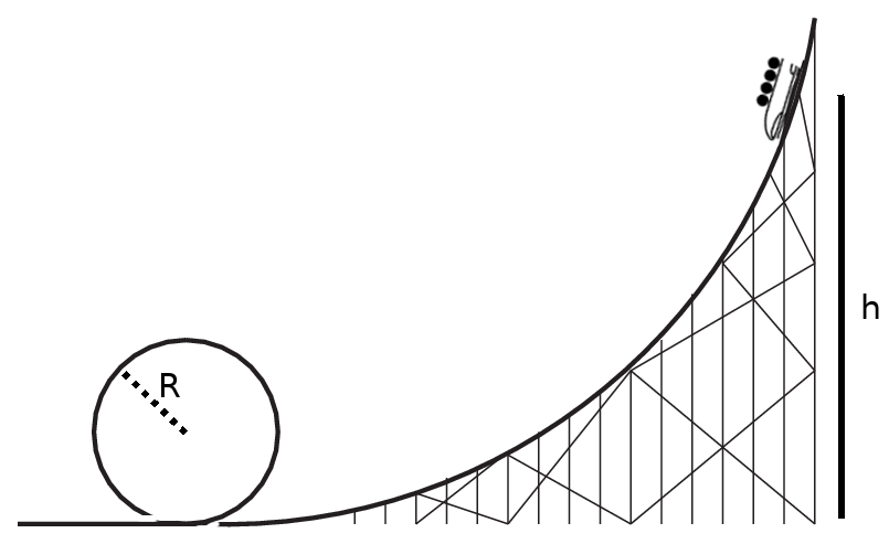
Consider a rollarcoaster with a loop, shown in the figure above. The car starts at rest a height of \(h=35\) m above the loop, flies down the track and around the loop, which has a radius of \(R=7\) m. The car has a mass of 550 kg.
- (energy review!) What speed is the car traveling at the top of the loop, if the track is completely frictionless?
- What is the acceleration of the car at the top of the loop?
- What is the normal force on the car at the top of the loop?

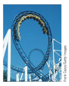
Consider the rollarcoaster loop in the figure, which has a teardrop shape. The cars ride on the inside of the loop and travel fast enough to ensure that the car stays on the track. The largest of these loops is 40 m high (*but not a circle!*) and the cars travel at a speed of 13 m/s at the top of the loop. At the top, the riders experience a centripetal acceleration of 2\(g\).
- What is the radius of the arc of the track at the top?
- If the mass of the car plus the riders is 1150 kg, what force does the track exert on the car at the top of the track?
- If the designers had made this a circular loop of radius 20 m (so the same total height as the teardrop), what would the centripetal acceleration of the riders at the top be, assuming the car had the same speed as in the teardrop shape?
- Which is more fun, a teardrop or a loop?
Example \(\PageIndex{3}\): The penny on the turntable
Suppose that you have a penny sitting on a turntable, a distance \(d\) = 10 cm from the axis of rotation. Assume the turntable starts moving, steadily spinning up from rest, in such a way that after 1.3 seconds it has reached its final rotation rate of 33.3 rpm (revolutions per minute). Answer the following questions:
- What was the turntable’s angular acceleration over the time interval from \(t\) = 0 to \(t\) = 1.3 s?
- How many turns (complete and fractional) did the turntable make before reaching its final velocity?
- Assuming the penny has not slipped, what is its centripetal acceleration once the turntable reaches its final velocity?
- How large does the static friction coefficient between the penny and the turntable have to be for the penny not to slip throughout this process?
Solution
(a) We are told that the turntable spins up “steadily” from \(t\) = 0 to \(t\) = 1.3 s. The word “steadily” here is a keyword that means the (angular) acceleration is constant (that is, the angular velocity increases at a constant rate).
What is this rate? For constant \(\alpha\), we have, from Equation (20.1.10), \(\alpha = \Delta \omega / \Delta t\). Here, the time interval \(\Delta t\) = 1.3 , so we just need to find \(\Delta \omega\). By definition, \(\Delta \omega = \omega_f − \omega_i\), and since we start from rest, \(\omega_i\) = 0. So we just need \(\omega_f\). We are told that “the final rotation rate” is 33.3 rpm (revolutions per minute). What does this tell us about the angular velocity?
The angular velocity is the number of radians an object moving in a circle (such as the penny in this example) travels per second. A complete turn around the circle, or revolution, corresponds to 180\(^{\circ}\), or equivalently 2\(\pi\) radians. So, 33.3 revolutions, or turns, per minute means \( 33.3 \times 2 \pi \) radians per 60 s, that is,
\[ \omega_{f}=\frac{33.3 \times 2 \pi \: \mathrm{rad}}{60 \: \mathrm{s}}=3.49 \: \frac{\mathrm{rad}}{\mathrm{s}} \label{eq:8.39} .\]
The angular acceleration, therefore, is
\[ \alpha=\frac{\Delta \omega}{\Delta t}=\frac{\omega_{f}-\omega_{i}}{\Delta t}=\frac{3.49 \: \mathrm{rad} / \mathrm{s}}{1.3 \: \mathrm{s}}=2.68 \: \frac{\mathrm{rad}}{\mathrm{s}^{2}} \label{eq:8.40} .\]
(b) The way to answer this question is to find out the total angular displacement, \(\Delta \theta\), of the penny over the time interval considered (from \(t\) = 0 to \(t\) = 1.3 s), and then convert this to a number of turns, using the relationship 2\(\pi\) rad = 1 turn. To get \(\Delta \theta\), we should use the equation (20.1.11) for motion with constant angular acceleration:
\[ \Delta \theta=\omega_{i} \Delta t+\frac{1}{2} \alpha(\Delta t)^{2} \label{eq:8.41} .\]
We start from rest, so \(\omega_i\) = 0, We know \(\Delta t\) = 1.3 s, and we just calculated \(\alpha\) = 2.68 rad/s2, so we have
\[ \Delta \theta=\frac{1}{2} \times 2.68 \: \frac{\mathrm{rad}}{\mathrm{s}^{2}} \times(1.3 \: \mathrm{s})^{2}=2.26 \: \mathrm{rad} \label{eq:8.42} .\]
This is less than 2\(\pi\) radians, so it takes the turntable less than one complete revolution to reach its final angular velocity. To be precise, since 2\(\pi\) radians is one turn, 2.26 rad will be 2.26/(2\(\pi\)) turns, which is to say, 0.36 turns—a little more than 1/3 of a turn.
(c) For the questions above, the penny just served as a marker to keep track of the revolutions of the turntable. Now, we turn to the dynamics of the motion of the penny itself. First, to get its angular acceleration, we can just use Equation (20.1.15), in the form
\[ a_{c}=R \omega^{2}=0.1 \: \mathrm{m} \times\left(3.49 \: \frac{\mathrm{rad}}{\mathrm{s}}\right)^{2}=1.22 \: \frac{\mathrm{m}}{\mathrm{s}^{2}} \label{eq:8.43} \]
noticing that \(R\), the radius of the circle on which the penny moves, is just the distance \(d\) to the axis of rotation that we were given at the beginning of the problem, and \(\omega\), its angular velocity, is just the final angular velocity of the turntable (assuming, as we are told, that the penny has not slipped relative to the turntable).
(d) Finally, how about the force needed to keep the penny from slipping—that is to say, to keep it moving with the turntable? This is just the centripetal force needed “bend” the trajectory of the penny into a circle of radius \(R\), so \(F_c = ma_c\), where \(m\) is the mass of the penny and \(a_c\) is the centripetal acceleration we just calculated. Physically, we know that this force has to be provided by the static (as long as the penny does not slip!) friction force between the penny and the turntable. We know that \(F^{s} \leq \mu_{s} F^{n}\), and we have for the normal force, in this simple situation, just \(F^n = mg\). Therefore, setting \(F^s = ma_c\) we have:
\[ m a_{c}=F^{s} \leq \mu_{s} F^{n}=\mu_{s} m g \label{eq:8.44} .\]
This is equivalent to the single inequality \(ma_c \leq \mu_smg\), where we can cancel out the mass of the penny to conclude that we must have \(a_c \leq \mu_sg\), and therefore
\[ \mu_{s} \geq \frac{a_{c}}{g}=\frac{1.22 \: \mathrm{m} / \mathrm{s}^{2}}{9.8 \: \mathrm{m} / \mathrm{s}^{2}}=0.124 \label{eq:8.45} \]
Example \(\PageIndex{4}\): Rotating frames of reference- centrifugal force and coriolis force
Imagine you are inside a rotating cylindrical room of radius \(R\). There is a metal puck on the floor, a distance \(r\) from the axis of rotation, held in place with an electromagnet. At some time you switch off the electromagnet and the puck is free to slide without friction. Find where the puck strikes the wall, and show that, if it was not too far away from the wall to begin with, it appears as if it had moved straight for the wall as soon as it was released.
Solution
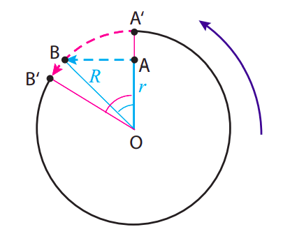
The picture looks as shown below, to an observer in an inertial frame, looking down. The puck starts at point A, with instantaneous velocity \(\omega r\) pointing straight to the left at the moment it is released, so it just moves straight (in the inertial frame) until it hits the wall at point B. From the cyan-colored triangle shown, we can see that it travels a distance \(\sqrt{R^{2}-r^{2}}\), which takes a time
\[ \Delta t=\frac{\sqrt{R^{2}-r^{2}}}{\omega r} \label{eq:8.62} .\]
In this time, the room rotates counterclockwise through an angle \(\Delta \theta_{room} = \omega \Delta t\):
\[ \Delta \theta_{\text {room}}=\frac{\sqrt{R^{2}-r^{2}}}{r} \label{eq:8.63} .\]

This is the angle shown in magenta in the figure. As a result of this rotation, the point A\(^{\prime}\) that was initially on the wall straight across from the puck has moved (following the magenta dashed line) to the position B\(^{\prime}\), so to an observer in the rotating room, looking at things from the point O, the puck appears to head for the wall and drift a little to the right while doing so.
The cyan angle in the picture, which we could call \(\Delta \theta_{part}\), has tangent equal to \(\sqrt{R^{2}-r^{2}} / r\), so we have
\[ \Delta \theta_{\text {room}}=\tan \left(\Delta \theta_{\text {part}}\right) \label{eq:8.64} .\]
This tells us the two angles are going to be pretty close if they are small enough, which is what happens if the puck starts close enough to the wall in the first place. The picture shows, for clarity, the case when \(r = 0.7R\), which gives \(\Delta \theta_{room}\) = 1.02 rad, and \(\Delta \theta_{part} = \tan^{−1}(1.02)\) = 0.8 rad. For \(r = 0.9R\), on the other hand, one finds \(\Delta \theta_{room}\) = 0.48 rad, and \(\Delta \theta_{part} = \tan^{−1}\)(0.48) = 0.45 rad.
In terms of pseudoforces (forces that do not, physically, exist, but may be introduced to describe mathematically the motion of objects in non-inertial frames of reference), the non-inertial observer would say that the puck heads towards the wall because of a centrifugal force (that is, a force pointing away from the center of rotation), and while doing so it drifts to the right because of the so-called Coriolis force.


