6.3: LIGO
- Page ID
- 45410
\( \newcommand{\vecs}[1]{\overset { \scriptstyle \rightharpoonup} {\mathbf{#1}} } \)
\( \newcommand{\vecd}[1]{\overset{-\!-\!\rightharpoonup}{\vphantom{a}\smash {#1}}} \)
\( \newcommand{\dsum}{\displaystyle\sum\limits} \)
\( \newcommand{\dint}{\displaystyle\int\limits} \)
\( \newcommand{\dlim}{\displaystyle\lim\limits} \)
\( \newcommand{\id}{\mathrm{id}}\) \( \newcommand{\Span}{\mathrm{span}}\)
( \newcommand{\kernel}{\mathrm{null}\,}\) \( \newcommand{\range}{\mathrm{range}\,}\)
\( \newcommand{\RealPart}{\mathrm{Re}}\) \( \newcommand{\ImaginaryPart}{\mathrm{Im}}\)
\( \newcommand{\Argument}{\mathrm{Arg}}\) \( \newcommand{\norm}[1]{\| #1 \|}\)
\( \newcommand{\inner}[2]{\langle #1, #2 \rangle}\)
\( \newcommand{\Span}{\mathrm{span}}\)
\( \newcommand{\id}{\mathrm{id}}\)
\( \newcommand{\Span}{\mathrm{span}}\)
\( \newcommand{\kernel}{\mathrm{null}\,}\)
\( \newcommand{\range}{\mathrm{range}\,}\)
\( \newcommand{\RealPart}{\mathrm{Re}}\)
\( \newcommand{\ImaginaryPart}{\mathrm{Im}}\)
\( \newcommand{\Argument}{\mathrm{Arg}}\)
\( \newcommand{\norm}[1]{\| #1 \|}\)
\( \newcommand{\inner}[2]{\langle #1, #2 \rangle}\)
\( \newcommand{\Span}{\mathrm{span}}\) \( \newcommand{\AA}{\unicode[.8,0]{x212B}}\)
\( \newcommand{\vectorA}[1]{\vec{#1}} % arrow\)
\( \newcommand{\vectorAt}[1]{\vec{\text{#1}}} % arrow\)
\( \newcommand{\vectorB}[1]{\overset { \scriptstyle \rightharpoonup} {\mathbf{#1}} } \)
\( \newcommand{\vectorC}[1]{\textbf{#1}} \)
\( \newcommand{\vectorD}[1]{\overrightarrow{#1}} \)
\( \newcommand{\vectorDt}[1]{\overrightarrow{\text{#1}}} \)
\( \newcommand{\vectE}[1]{\overset{-\!-\!\rightharpoonup}{\vphantom{a}\smash{\mathbf {#1}}}} \)
\( \newcommand{\vecs}[1]{\overset { \scriptstyle \rightharpoonup} {\mathbf{#1}} } \)
\(\newcommand{\longvect}{\overrightarrow}\)
\( \newcommand{\vecd}[1]{\overset{-\!-\!\rightharpoonup}{\vphantom{a}\smash {#1}}} \)
\(\newcommand{\avec}{\mathbf a}\) \(\newcommand{\bvec}{\mathbf b}\) \(\newcommand{\cvec}{\mathbf c}\) \(\newcommand{\dvec}{\mathbf d}\) \(\newcommand{\dtil}{\widetilde{\mathbf d}}\) \(\newcommand{\evec}{\mathbf e}\) \(\newcommand{\fvec}{\mathbf f}\) \(\newcommand{\nvec}{\mathbf n}\) \(\newcommand{\pvec}{\mathbf p}\) \(\newcommand{\qvec}{\mathbf q}\) \(\newcommand{\svec}{\mathbf s}\) \(\newcommand{\tvec}{\mathbf t}\) \(\newcommand{\uvec}{\mathbf u}\) \(\newcommand{\vvec}{\mathbf v}\) \(\newcommand{\wvec}{\mathbf w}\) \(\newcommand{\xvec}{\mathbf x}\) \(\newcommand{\yvec}{\mathbf y}\) \(\newcommand{\zvec}{\mathbf z}\) \(\newcommand{\rvec}{\mathbf r}\) \(\newcommand{\mvec}{\mathbf m}\) \(\newcommand{\zerovec}{\mathbf 0}\) \(\newcommand{\onevec}{\mathbf 1}\) \(\newcommand{\real}{\mathbb R}\) \(\newcommand{\twovec}[2]{\left[\begin{array}{r}#1 \\ #2 \end{array}\right]}\) \(\newcommand{\ctwovec}[2]{\left[\begin{array}{c}#1 \\ #2 \end{array}\right]}\) \(\newcommand{\threevec}[3]{\left[\begin{array}{r}#1 \\ #2 \\ #3 \end{array}\right]}\) \(\newcommand{\cthreevec}[3]{\left[\begin{array}{c}#1 \\ #2 \\ #3 \end{array}\right]}\) \(\newcommand{\fourvec}[4]{\left[\begin{array}{r}#1 \\ #2 \\ #3 \\ #4 \end{array}\right]}\) \(\newcommand{\cfourvec}[4]{\left[\begin{array}{c}#1 \\ #2 \\ #3 \\ #4 \end{array}\right]}\) \(\newcommand{\fivevec}[5]{\left[\begin{array}{r}#1 \\ #2 \\ #3 \\ #4 \\ #5 \\ \end{array}\right]}\) \(\newcommand{\cfivevec}[5]{\left[\begin{array}{c}#1 \\ #2 \\ #3 \\ #4 \\ #5 \\ \end{array}\right]}\) \(\newcommand{\mattwo}[4]{\left[\begin{array}{rr}#1 \amp #2 \\ #3 \amp #4 \\ \end{array}\right]}\) \(\newcommand{\laspan}[1]{\text{Span}\{#1\}}\) \(\newcommand{\bcal}{\cal B}\) \(\newcommand{\ccal}{\cal C}\) \(\newcommand{\scal}{\cal S}\) \(\newcommand{\wcal}{\cal W}\) \(\newcommand{\ecal}{\cal E}\) \(\newcommand{\coords}[2]{\left\{#1\right\}_{#2}}\) \(\newcommand{\gray}[1]{\color{gray}{#1}}\) \(\newcommand{\lgray}[1]{\color{lightgray}{#1}}\) \(\newcommand{\rank}{\operatorname{rank}}\) \(\newcommand{\row}{\text{Row}}\) \(\newcommand{\col}{\text{Col}}\) \(\renewcommand{\row}{\text{Row}}\) \(\newcommand{\nul}{\text{Nul}}\) \(\newcommand{\var}{\text{Var}}\) \(\newcommand{\corr}{\text{corr}}\) \(\newcommand{\len}[1]{\left|#1\right|}\) \(\newcommand{\bbar}{\overline{\bvec}}\) \(\newcommand{\bhat}{\widehat{\bvec}}\) \(\newcommand{\bperp}{\bvec^\perp}\) \(\newcommand{\xhat}{\widehat{\xvec}}\) \(\newcommand{\vhat}{\widehat{\vvec}}\) \(\newcommand{\uhat}{\widehat{\uvec}}\) \(\newcommand{\what}{\widehat{\wvec}}\) \(\newcommand{\Sighat}{\widehat{\Sigma}}\) \(\newcommand{\lt}{<}\) \(\newcommand{\gt}{>}\) \(\newcommand{\amp}{&}\) \(\definecolor{fillinmathshade}{gray}{0.9}\)The first discovery of a gravitational wave occurred at the Laser Interferometer Gravitational Wave Observatory (LIGO) in September of 2015. LIGO actually consists of two detectors, one in Hanford, Washington, and the other in Livingston, Louisiana (see Figure \(\PageIndex{1}\)). One of the reasons for having two detectors is because any real gravitational wave would necessarily have to travel though both detectors; if only one detector sees what it thinks is a gravitational wave, then it could just be noise. Another benefit of having two detectors is that it helps in determining where the gravitational wave came from; whichever detector registers the wave first must be closer to the source of the wave.
The detectors themselves are interferometers with arms that each have a length of 4 km, as shown in Figure \(\PageIndex{2}\). The purpose of an interferometer is to split a single beam of light into two parts and then recombine them such that they interfere with one another. If the two parts travel exactly the same distance or if the path difference is an integer multiple of the wavelength, then the light beams interfere constructively. If the path difference is an odd multiple of a half-wavelength, then the light beams interfere completely destructively.

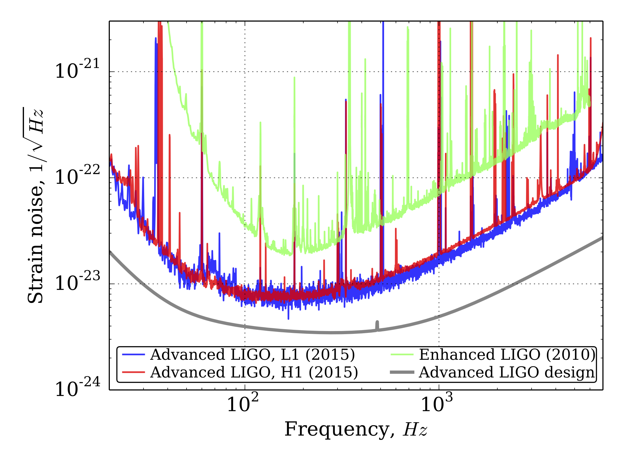
In most interferometers, the mirrors are fixed to a surface such that their positions can be adjusted. By observing how the level of interference changes as you adjust the positions of the mirrors, you can determine the wavelength of the light (for example). In LIGO, the mirrors are instead suspended by systems that aim to decouple them from ground disturbances as much as possible, which makes them similar to free-floating objects. In this way, changes in the path lengths of the two arms can be caused by gravitational waves. The tricky part, however, is determining what motions of the mirrors are due to gravitational waves versus other sources. To do that, you can run the detector in the absence of gravitational waves (which is most of the time) and see what the signal at the detector looks like. This is called strain noise (Figure \(\PageIndex{3}\)). Then you look for deviations from the noise. It also helps that gravitational waves have a very distinct signal, which we will talk about later.

You may be wondering why the vertical axis in Figure \(\PageIndex{3}\) has such unusual units. In experiment, a detector's sensitivity often varies with the frequency of the incoming signal. This is often described using a power spectral density (PSD) graph, which indicates how much energy is received by the detector per unit time over a range of frequencies. (If that sounds confusing, try imagining that the range of frequencies is discrete instead of continuous. The PSD shows how much energy is received at each of those frequencies.) The integral over a particular range of frequencies (i.e. the area under the curve) then tells you the total power received by the detector. Related to the PSD is something called an amplitude spectral density (ASD) graph. The power contained in a wave is proportional to the square of the amplitude of the wave, so you can get an ASD graph by taking the square root of the PSD's vertical axis. That is why you see \(\sqrt{\text{Hz}}\) in the denominator of the unit for the vertical axis in Figure \(\PageIndex{3}\).
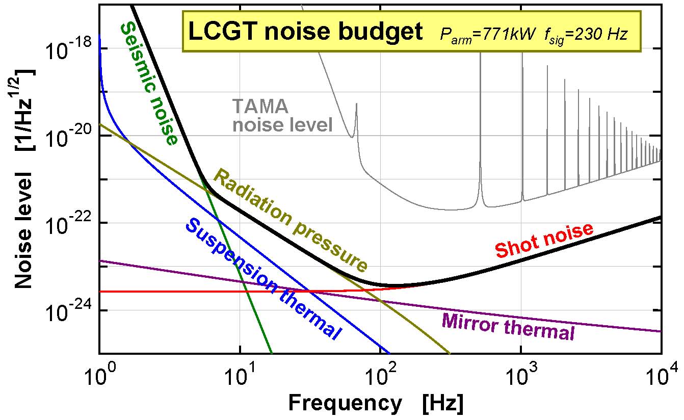
Figure \(\PageIndex{4}\) breaks down the noise by source. Unsurprisingly, motion of the ground itself is a significant problem, but only at very low frequencies. Also note that a significant source of noise is radiation pressure, which is pressure exerted on the mirrors from photons. A typical task in Modern Physics courses is to learn how to calculate the momentum of a photon, and here we see why that actually matters.

You can also see from Fig. \(\PageIndex{4}\) that the peak sensitivity occurs on the order of 100 Hz. It is not a coincidence that this happens to be right around the frequency of gravitational waves produced by binary black hole mergers (we will talk more about that in the next section). That is good experimental design!
One concern that some people have when they learn how a gravitational wave interferometer works is that the wavelength of the laser light will be stretched along with the gravitational wave, which would defeat the purpose of using an interferometer in the first place. It seems especially bad when you consider the fact that the laser actually bounces back and forth between the mirrors 300 times before being received by the detector (this effectively increases the path length difference). This is not actually a problem, though, because while the interferometer arms are there for the entire stretch-compress cycle, a laser pulse travels fast enough that it is only present for a tiny portion of the stretch-compress cycle. In other words, the laser pulse doesn't exist for long enough for its wavelength to even be stretched or compressed by the gravitational wave. Do the math to argue that this is the case.
- Answer
-
The light takes an 8 km round trip (4 km out and another 4 km back) 300 times. The time it takes to make this trip is
\[\Delta t=\frac{(8000\text{ m})(300)}{3\times 10^8\text{ m/s}}=0.008\text{ s}\nonumber.\]
Meanwhile, the period of a gravitational wave is approximately \(T=\frac{1}{f}\approx \frac{1}{100\text{ Hz}}=0.01 \text{ s}\). The time the light spends in the interferometer, then, is less than one tenth of the time of a full stretch-compress cycle. So while the wavelength of the light will be stretched by the gravitational wave by a little bit, it isn't stretched by so much as to defeat the purpose of using an interferometer.


