
6.3: Applying the Force Model
- Page ID
- 56286

\( \newcommand{\vecs}[1]{\overset { \scriptstyle \rightharpoonup} {\mathbf{#1}} } \)
\( \newcommand{\vecd}[1]{\overset{-\!-\!\rightharpoonup}{\vphantom{a}\smash {#1}}} \)
\( \newcommand{\dsum}{\displaystyle\sum\limits} \)
\( \newcommand{\dint}{\displaystyle\int\limits} \)
\( \newcommand{\dlim}{\displaystyle\lim\limits} \)
\( \newcommand{\id}{\mathrm{id}}\) \( \newcommand{\Span}{\mathrm{span}}\)
( \newcommand{\kernel}{\mathrm{null}\,}\) \( \newcommand{\range}{\mathrm{range}\,}\)
\( \newcommand{\RealPart}{\mathrm{Re}}\) \( \newcommand{\ImaginaryPart}{\mathrm{Im}}\)
\( \newcommand{\Argument}{\mathrm{Arg}}\) \( \newcommand{\norm}[1]{\| #1 \|}\)
\( \newcommand{\inner}[2]{\langle #1, #2 \rangle}\)
\( \newcommand{\Span}{\mathrm{span}}\)
\( \newcommand{\id}{\mathrm{id}}\)
\( \newcommand{\Span}{\mathrm{span}}\)
\( \newcommand{\kernel}{\mathrm{null}\,}\)
\( \newcommand{\range}{\mathrm{range}\,}\)
\( \newcommand{\RealPart}{\mathrm{Re}}\)
\( \newcommand{\ImaginaryPart}{\mathrm{Im}}\)
\( \newcommand{\Argument}{\mathrm{Arg}}\)
\( \newcommand{\norm}[1]{\| #1 \|}\)
\( \newcommand{\inner}[2]{\langle #1, #2 \rangle}\)
\( \newcommand{\Span}{\mathrm{span}}\) \( \newcommand{\AA}{\unicode[.8,0]{x212B}}\)
\( \newcommand{\vectorA}[1]{\vec{#1}} % arrow\)
\( \newcommand{\vectorAt}[1]{\vec{\text{#1}}} % arrow\)
\( \newcommand{\vectorB}[1]{\overset { \scriptstyle \rightharpoonup} {\mathbf{#1}} } \)
\( \newcommand{\vectorC}[1]{\textbf{#1}} \)
\( \newcommand{\vectorD}[1]{\overrightarrow{#1}} \)
\( \newcommand{\vectorDt}[1]{\overrightarrow{\text{#1}}} \)
\( \newcommand{\vectE}[1]{\overset{-\!-\!\rightharpoonup}{\vphantom{a}\smash{\mathbf {#1}}}} \)
\( \newcommand{\vecs}[1]{\overset { \scriptstyle \rightharpoonup} {\mathbf{#1}} } \)
\(\newcommand{\longvect}{\overrightarrow}\)
\( \newcommand{\vecd}[1]{\overset{-\!-\!\rightharpoonup}{\vphantom{a}\smash {#1}}} \)
\(\newcommand{\avec}{\mathbf a}\) \(\newcommand{\bvec}{\mathbf b}\) \(\newcommand{\cvec}{\mathbf c}\) \(\newcommand{\dvec}{\mathbf d}\) \(\newcommand{\dtil}{\widetilde{\mathbf d}}\) \(\newcommand{\evec}{\mathbf e}\) \(\newcommand{\fvec}{\mathbf f}\) \(\newcommand{\nvec}{\mathbf n}\) \(\newcommand{\pvec}{\mathbf p}\) \(\newcommand{\qvec}{\mathbf q}\) \(\newcommand{\svec}{\mathbf s}\) \(\newcommand{\tvec}{\mathbf t}\) \(\newcommand{\uvec}{\mathbf u}\) \(\newcommand{\vvec}{\mathbf v}\) \(\newcommand{\wvec}{\mathbf w}\) \(\newcommand{\xvec}{\mathbf x}\) \(\newcommand{\yvec}{\mathbf y}\) \(\newcommand{\zvec}{\mathbf z}\) \(\newcommand{\rvec}{\mathbf r}\) \(\newcommand{\mvec}{\mathbf m}\) \(\newcommand{\zerovec}{\mathbf 0}\) \(\newcommand{\onevec}{\mathbf 1}\) \(\newcommand{\real}{\mathbb R}\) \(\newcommand{\twovec}[2]{\left[\begin{array}{r}#1 \\ #2 \end{array}\right]}\) \(\newcommand{\ctwovec}[2]{\left[\begin{array}{c}#1 \\ #2 \end{array}\right]}\) \(\newcommand{\threevec}[3]{\left[\begin{array}{r}#1 \\ #2 \\ #3 \end{array}\right]}\) \(\newcommand{\cthreevec}[3]{\left[\begin{array}{c}#1 \\ #2 \\ #3 \end{array}\right]}\) \(\newcommand{\fourvec}[4]{\left[\begin{array}{r}#1 \\ #2 \\ #3 \\ #4 \end{array}\right]}\) \(\newcommand{\cfourvec}[4]{\left[\begin{array}{c}#1 \\ #2 \\ #3 \\ #4 \end{array}\right]}\) \(\newcommand{\fivevec}[5]{\left[\begin{array}{r}#1 \\ #2 \\ #3 \\ #4 \\ #5 \\ \end{array}\right]}\) \(\newcommand{\cfivevec}[5]{\left[\begin{array}{c}#1 \\ #2 \\ #3 \\ #4 \\ #5 \\ \end{array}\right]}\) \(\newcommand{\mattwo}[4]{\left[\begin{array}{rr}#1 \amp #2 \\ #3 \amp #4 \\ \end{array}\right]}\) \(\newcommand{\laspan}[1]{\text{Span}\{#1\}}\) \(\newcommand{\bcal}{\cal B}\) \(\newcommand{\ccal}{\cal C}\) \(\newcommand{\scal}{\cal S}\) \(\newcommand{\wcal}{\cal W}\) \(\newcommand{\ecal}{\cal E}\) \(\newcommand{\coords}[2]{\left\{#1\right\}_{#2}}\) \(\newcommand{\gray}[1]{\color{gray}{#1}}\) \(\newcommand{\lgray}[1]{\color{lightgray}{#1}}\) \(\newcommand{\rank}{\operatorname{rank}}\) \(\newcommand{\row}{\text{Row}}\) \(\newcommand{\col}{\text{Col}}\) \(\renewcommand{\row}{\text{Row}}\) \(\newcommand{\nul}{\text{Nul}}\) \(\newcommand{\var}{\text{Var}}\) \(\newcommand{\corr}{\text{corr}}\) \(\newcommand{\len}[1]{\left|#1\right|}\) \(\newcommand{\bbar}{\overline{\bvec}}\) \(\newcommand{\bhat}{\widehat{\bvec}}\) \(\newcommand{\bperp}{\bvec^\perp}\) \(\newcommand{\xhat}{\widehat{\xvec}}\) \(\newcommand{\vhat}{\widehat{\vvec}}\) \(\newcommand{\uhat}{\widehat{\uvec}}\) \(\newcommand{\what}{\widehat{\wvec}}\) \(\newcommand{\Sighat}{\widehat{\Sigma}}\) \(\newcommand{\lt}{<}\) \(\newcommand{\gt}{>}\) \(\newcommand{\amp}{&}\) \(\definecolor{fillinmathshade}{gray}{0.9}\)Free-Body Diagrams
When we want to analyze a physical situation in terms of forces, it is necessary to focus on forces acting on a particular object or a collection of objects. We will always be interested in the net force on a particular system. To help in identifying forces that act on a particular object it is helpful to pictorially represent the forces as clearly labeled arrows on a diagram. There is a standard convention for representing forces like this, called a free-body diagram or FBD. We will also sometimes refer to this diagram as a force diagram.
The following is a list of common conventions that we will follow when making a force diagram. It is important to be familiar with these and strictly follow them; it will make things clearer in the long run:
- A force diagram refers only to one system. A system might consist of one object or multiple objects, and the forces that act on that system must come from objects or systems which are not part of the defined system.
- The system is shown as an enlarged dot in a force diagram. The dot is clearly labeled to indicate what system it refers to.
- All the forces acting on the chosen system are shown on the force diagram. Forces that the system exerts on other systems are not shown on its own force diagram. You should never find forces that represent a third-law pair on the same FBD.
- Forces like friction and weight (that act over multiple points) are modeled as a single force acting at a single point.
- To avoid confusion, we usually don't show velocity or other vector quantities on the force diagram.
- If a particular force has components in multiple directions, it is useful to draw separate arrows for each component, since it will help with finding the net force in each spacial direction.
- A net force vector can be added to the force diagram, but there should be a clear indication that the force is the sum of all the forcing acting in the system, rather than a new force.
Figure 6.3.1 shows a free-body diagram of the example we analyzed in the previous section. The picture on the left is a diagram of the physical situation showing all the forces that act on the box as a person pushes it against the wall while keeping it in place. There are two FDBs of this scenario shown. In both, the dot in the center represents our selected physical system, in this case the box. All the forces shown act on the box. By convention, the tails of the forces start at the dot representing the system.
Figure 6.3.1: Example of Free-Body Diagrams with Zero Net Force
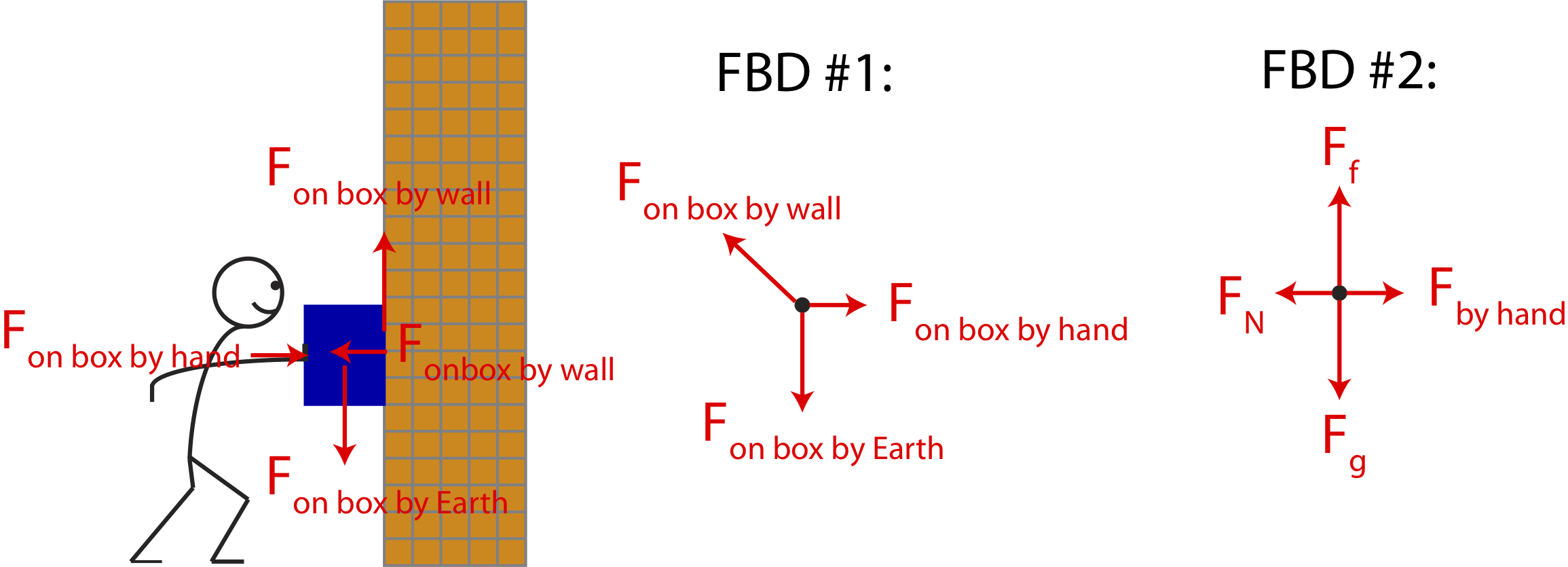
The central free-body diagram labeled FBD #1, shows three forces which represent the three objects with which the box is interacting: the hand, the wall, and the Earth. The "on by" notation in the central diagram stresses the fact that the forces present act on the box by these three objects. The force by the box on the wall points in the northwest direction because it shows the combined force by the wall, which is the sum of the vertical and horizontal components of this force shown in the left picture. The diagram labeled FBD #2 splits \(F_{\textrm{on box by wall}}\) into its vertical component, which represents the force of friction with the wall, \(F_f\), and its horizontal component which here represents the normal force, \(F_N\), which is perpendicular to the surface of the wall. Also, FBD #2 abbreviates the gravitational forces as \(F_g\) and drops all the "on box" notations. It is often more useful to start with labeling forces like in FBD #1 which assures that you are not missing any objects with which your system is interacting. Once you get more comfortable with forces with lots of practice, you may go straight to the notation used in FBD #2.
The arrows drawn in horizontal direction have the same length, so do the arrows in the vertical direction. This is to indicate that the forces are balanced. Since the box is stationary, the forces in both the x- and the y- directions must cancel. The fact that \(F_g\) arrow is drawn longer than the \(F_{\textrm{by hand}}\) arrow shows that these forces do not need to have the same magnitude. Of course, the reverse is possible, the force of the push could be greater than the weight of the box. In that case, the magnitude of the normal force would have to be greater than the magnitude of the frictional force.
Example \(\PageIndex{1}\)
Shown below is a tightrope walker who is balancing on a rope tied between two poles. The weight of the person is 600 N. The rope makes an angle of \(5^{\circ}\) with the horizontal.
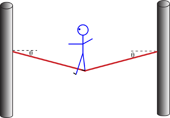
a) Draw a free-body diagram for the tightrope walker.
b) Explain why the tension in the rope to the right of the person's position must equal to the tension of the rope to the left of her position.
c) Calculate the tension in the rope.
- Solution
-
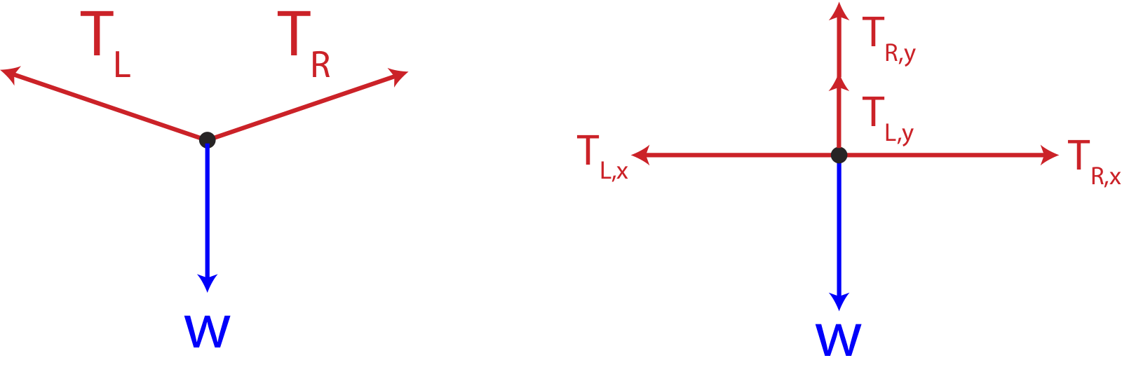
a) Since the person is stationary on the rope, there is no net force. The forces must be balanced in both the x- and y- directions:
\[\sum F_x=0\nonumber\]
\[\sum F_y=0\nonumber\]
Shown below is a free-body diagram for the tightrope walker. The left figure shows the three forces present: the weight, and the tension from each side of the rope relative to the position of the person. The right figure shows the forces by components, since we need to split the tension forces by components in order to balance them.
b) In the x-direction there are only two forces:
\[\sum F_x=T_{R,x}-T_{L,x}=0\nonumber\]
Thus, the x-components must be equal:
\[T_{R,x}=T_{L,x}\nonumber\]
In terms of angle and the magnitudes of the tension forces we get:
\[T_{R}\cos\theta=T_L\cos\theta\nonumber\]
Resulting in:
\[T_R=T_L\nonumber\]
Thus, the tensions on each side of the person are equal.
b) In the y-direction the forces are:
\[\sum F_y=T_{R,y}+T_{L,y}-w=0\nonumber\]
In terms of angle and magnitude and using the result from a), \(T=T_R=T_L\), we get:
\[2T\sin\theta-w=0\nonumber\]
Solving for T:
\[T=\frac{w}{2\sin\theta}=\frac{600 N}{2\sin 5^{\circ}}=3442 N\nonumber\]
In another example below, Figure 6.3.2 shows a student pushing a box on a surface of a table. Let us assume that the box is initially stationary and begins to move as the student pushes it. Based on Newton's 2nd Law this implies that the net force is no longer zero in the horizontal direction since the box experiences a change in velocity in that direction.
Figure 6.3.2: Example of Free-Body Diagrams with Non-zero Net Force
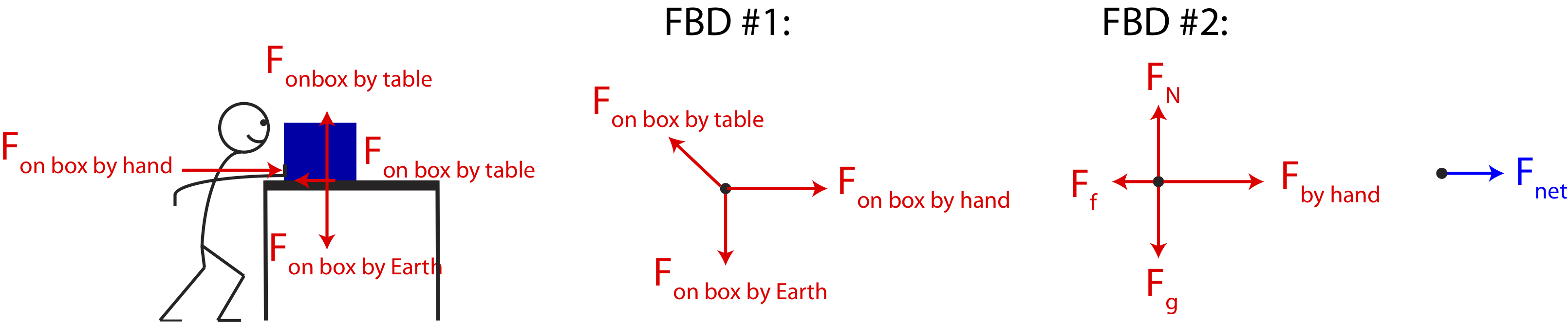
The force-diagrams drawn in the figure above indicate that the net force is not zero in this case. The box does not move in the vertical direction, so the force of gravity on the box must still be balanced with the vertical force exerted on the box by the table. In this case, the normal force is vertical, since it is perpendicular to the surface of the table which is horizontal. In the horizontal direction, however, the box changes its velocity from zero to non-zero, which implies an acceleration in the positive x-direction based on Newton's 2nd Law. This means that the force on the box by the pushing hand is greater than the frictional force on the box by the table which opposes motion and, and thus, points to the left. This is indicated in FBD #2 by drawing the \(F_{\textrm{by hand}}\) arrow longer than the \(F_f\) arrow. The diagram shown on the very right shows the net force, \(F_{net}\), which is the sum of all the forces in the FBDs. Note, it is better to draw the net force on a separate diagram, so it is not confused with all the physical forces which describe interactions, but rather its a force which is the summation of all of the physical forces present.
Example \(\PageIndex{2}\)
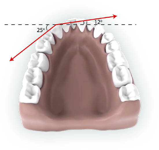
Braces are used to apply forces to teeth to realign them. Shown in this figure below are the tensions applied by the wire to a protruding tooth. The angles relative to the horizontal are marked in the figure. Calculate the total force (magnitude and direction) exerted on the tooth if the tension in wire is 18 N.
- Solution
-
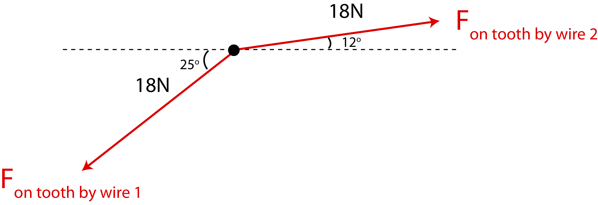
First, let's draw a FBD with the took being the system. The only forces applied to the tooth are the two tension forces as shown below.
In the x-direction the net force is:
\[F_{net,x}=18N\cos 12^{\circ}-18N\cos 25^{\circ}=1.29N\]
In the y-direction:
\[F_{net,y}=18N\sin 12^{\circ}-18N\sin 25^{\circ}=-3.86N\]
The magnitude is:
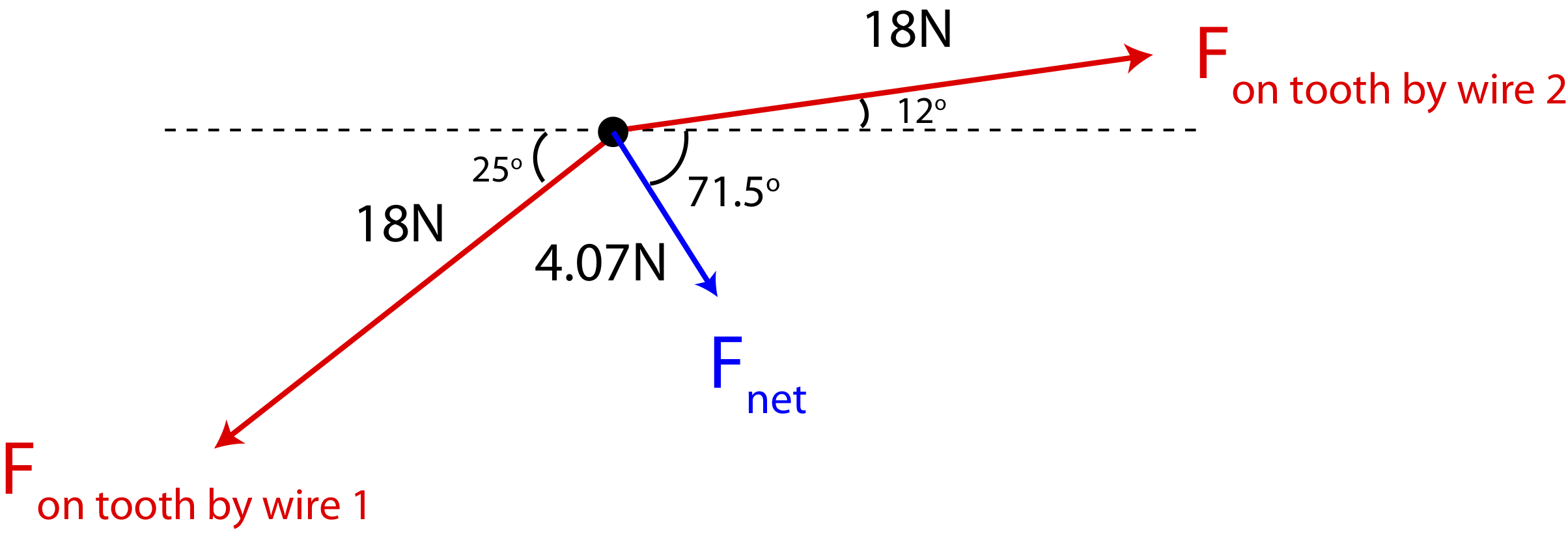
\[|\vec F_{net}|=\sqrt{F^2_{net,x}+F^2_{net,y}}=\sqrt{1.29^2+3.86^2}=4.07N\]
The direction is:
\[\arctan\Big(\frac{3.86}{1.29}\Big)=71.5^{\circ}\]
pointing southeast. The net force is added to the FBD below, pointing toward the center of the mouth such that the protruding tooth aligns with its neighboring teeth.
One Dimensional Acceleration
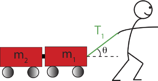
Let us look at an example where we can use information about the system's acceleration to determine forces involved. In the figure below a child pulls two carts with a rope, at an angle of \(30^{\circ}\) relative to the horizontal, along a frictionless surface. As a result the carts accelerate at the rate of \(2~\textrm{m/s}^2\). Assume \(m_1=0.5~\textrm{kg}\) and \(m_2=0.8~\textrm{kg}\).
Figure 6.3.3: Two Carts Pulled by a Rope
Below we outline some general problem-solving steps that can be applied to many types of problems that describe physical phenomemon explained by Newton's Laws. We apply these steps to answer multiple questions about the system in Figure 6.3.3. Given some angle and masses of the two carts, we aim to calculate the tension in the rope, the normal force by the surface on both cars and on each individual cart, and the force of one cart pushing on another.
Step 1: Define Physical System
The first thing we would like to determine is how to define our physical system to answer these questions. Since the questions all ask about forces on the cart(s), we want to include the cart(s) in the system, rather than the child, for example, since we are not trying to calculate any forces on the child at this point. But should our physical system include one of both carts? The forces between the carts and the normal force on each cart are forces on the individual carts. If we define our system as the two carts combined, then all the internal forces cancel, and we would not be able to answer those questions. But to find the tension in the rope it is sufficient to think of the system as the two carts combined, although it can still be done by thinking about each cart individually. Thus, we often choose our physical system based on the types of questions we are trying to answer and the simplicity of answering those questions.
Step 2: Draw a Free-Body Diagram
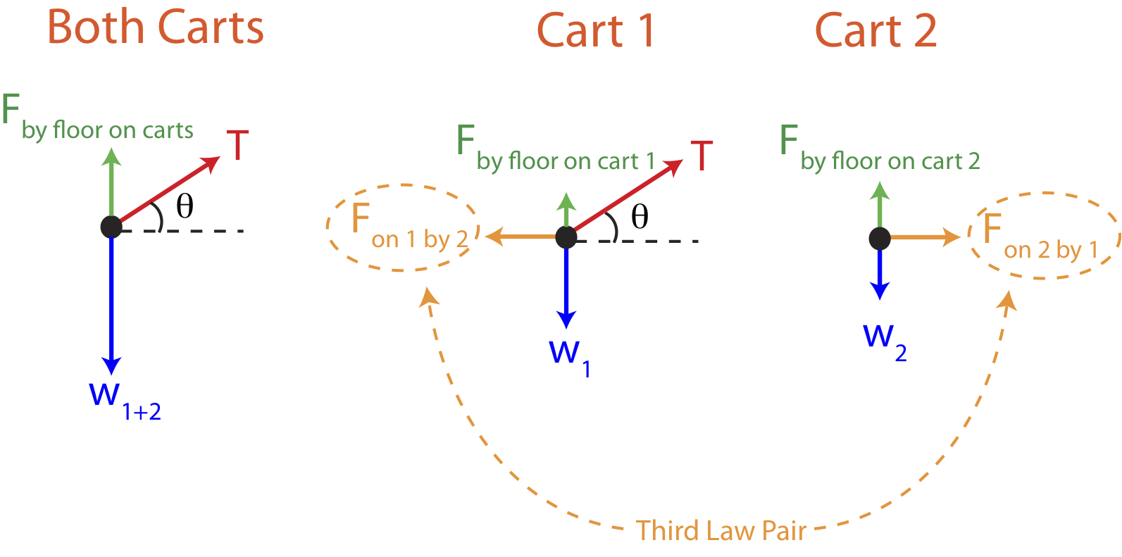
We start with definition the system as both carts combined. The free-body diagrams on this system is the first diagram from the left in Figure 6.3.4 below. Once we define our system to be composed of both carts, it no longer matters that two carts are present, and only the forces acting on the two carts are present in the FBD. These forces are either contact or long-range. Contact forces in this case are the force on the carts by the rope labeled as tension, \(T\), the force by the floor on the carts, \(F_{\textrm{by floor on carts}}\), also known as the normal force and can be abbreviated as \(F_{N,\textrm{carts}}\). The long-range force is the force on the carts by the Earth (the force of gravity) or the weight of the two carts, \(w_{1+2}=(m_1+m_2)g\).
Figure 6.3.4: Free-Body Diagrams For the Carts Scenario
Step 3: Split forces by Components
In order to apply Newton's Laws we first need to split all the forces into their components to solve for forces depending on acceleration in each spatial direction. In this example there is no acceleration in the y-direction (the motion is purely horizontal), but there is a non-zero acceleration in the x-direction. The only force that has both components is the tension force vector, \(\vec T\). By components the tension force is:
\[T_x=T\cos\theta\]
\[T_y=T\sin\theta\]
The angle \(\theta\) is given in this problem, so we aim to determine the magnitude of the tension force, \(T\), based on the information provided.
Step 4: Apply Newton's Laws in Each Spatial Direction and Solve for Unknowns
Once all the forces are expressed in terms of their components, we are ready to apply Newton's Laws. In the y-direction the acceleration is zero, so the forces must be balanced. The equation is the y-direction is:
\[\sum F_y =T\sin\theta+F_{\textrm{N,carts}}-(m_1+m_2)g=0\label{y-carts}\]
We can't yet solve for any unknown forces using the above equation since there are two unknowns, the tension and the normal force. So, let us move on to writing down the Newton's 2nd Law for the horizontal x-direction:
\[\sum F_x =T\cos\theta=(m_1+m_2)a\]
Since only the magnitude of the tension is unknown in the above equation, we can solve for it:
\[T=\frac{(m_1+m_2)a}{\cos\theta}=\frac{(0.5kg+0.8kg)(2 m/s^2)}{\cos 30^{\circ}}=3.0 N\label{T-carts}\]
Now we can return to Equation \ref{y-carts} for the y-direction and solve for the normal force:
\[F_{\textrm{N,carts}}=(m_1+m_2)g-T\sin\theta=(0.5kg+0.8kg)(9.8 m/s^2)-3N\sin 30^{\circ}=11.24 N\label{Fn-carts}\]
Alert
The normal force does not always equal to the weight of the object. This is only true when the weight of the system and the normal force are the only two forces present in the vertical direction, the surface which generates a normal force is horizontal, and the object is not accelerating.
Equation \ref{Fn-carts} demonstrates an example of a situation when the normal forces does not equal to the weight of the system, \(w_{1+2}=12.74 N\). This is because there is another force present in the vertical direction, the vertical component of the tension. Imagine holding an object by a vertical rope. Even if the object is still (just barely) in contact with the floor, the floor does not exert a normal force on the object, whose weight is fully supported by the rope.
Let us now return to step 1 in the problem solving procedure in order to calculate the forces between the two carts and the individual normal forces. Since the forces between the carts are internal to the two-cart system, they did not play a role on the two cart system. Thus, we need to redefine our system as consisting of just one of the carts. The middle illustration in Figure 6.3.4 shows the FBD for cart 1, where all the forces labeled act on cart one only. Similarly, the last figure from the left shows all the forces acting on cart 2. Note, the tension is no longer present in the FBD for cart 2 since the rope is not in physical contact with the second cart. Your intuition might tell you that cart 2 accelerates because of the child pulling on the rope. This is only an indirect effect. The force that acts on cart 2 that causes acceleration is the force due to cart 1 pulling on cart 2, not the tension force. But cart 1 accelerates due to the rope pulling on it. Using the middle FBD the forces in each spatial direction on cart 1 are:
\[\sum F_y =T\sin\theta+F_{\textrm{N,1}}-m_1g=0\label{y-cart1}\]
\[\sum F_x =T\cos\theta-F_{\textrm{on 1 by 2}}=m_1a\label{x-cart1}\]
We can use the result for the tension we found in Equation \ref{T-carts} to first solve for two unknown forces in the equation above, but we would like to demonstrate that we can also calculate the tension force by analyzing the two carts individually. Below are the two equations for cart 2 using the last FBD in Figure 6.3.4:
\[\sum F_y =F_{\textrm{N,2}}-m_2g=0\]
\[\sum F_x =F_{\textrm{on 2 by 1}}=m_2a\]
Solving for the normal force on cart 2 we find:
\[F_{\textrm{N,2}}=m_2g=(0.8 kg)(9.8 m/s^2)=7.84 N\]
We can see that we can solve for the force on cart 2 by car 1 immediately since there is not tension acting directly on cart 2:
\[F_{\textrm{on 2 by 1}}=m_2a=(0.8 kg)(2 m/s^2)= 1.6 N\]
Next we can use Newton's Third Law to obtain the force on cart 1 by cart 2. The Third Law pair is marked in Figure 6.3.4, identified because the "on by" notation is switched in the two forces which must be equal in magnitude and point in opposite directions. Thus, we can use the 3rd law and solve for the tension force using Equation \ref{x-cart1}:
\[T=\frac{F_{\textrm{on 1 by 2}}+m_1a}{\cos\theta}=\frac{1.6 N+(0.5 kg)(2 m/s^2)}{\cos 30^{\circ}}=3.0 N\]
We obtain the same results as we did in Equation \ref{T-carts} using the two-cart system. if our only goal was to calculate the tension in the rope, doing the method outlined above of treating each cart individually would be unnecessary work, since you need more equation and calculation to solve for the tension. But since we are also interested in calculating the forces between the two carts, we see that this method produces the same result.
Lastly, solving for the normal force on cart 1 using Equation \ref{y-cart1} we find:
\[F_{\textrm{N,1}}=m_1g-T\sin\theta=(0.5 kg)(9.8 m/s^2)-3N\sin 30^{\circ}=3.4 N\]
We can see that the total normal force obtained in Equation \ref{Fn-carts} is the sum on the individual normal forces:
\[F_{\textrm{N,carts}}=F_{\textrm{N,1}}+F_{\textrm{N,2}}=3.4N+7.84N=11.24 N\]
This result can be seen by looking at the three FBDs in Figure 6.3.4. The combined FBD shows that the total normal force plus the y-component of the tension force equals to the total weight of the two carts, which is the result you can get by combining the two FBDs for each cart.
Two Dimensional Acceleration
The example we worked out above involved acceleration in one dimension, although there were forces acting in both direction. We will not look at an example when the acceleration is two-dimensional. And we do so by analyzing a special phenomemon of an object moving in a horizontal circle at constant speed. Imagine holding a ball attached by a string and twirling it around in a horizontal circle. As first guess you might think that the ball has zero acceleration since it is moving with a constant speed, but we need to be careful here. Acceleration is the change and velocity, so we need to think about both speed and direction before making such conclusions.
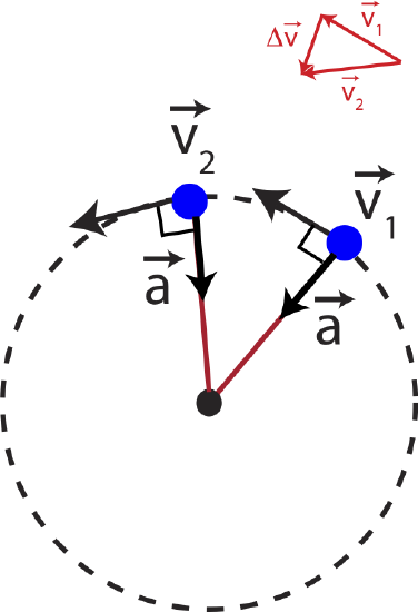
Figure 6.3.5 above shows the top view of a ball (blue dot) moving a circle. The vectors tangent to the circle represent the velocity of the ball at different locations of its motion. Although, the length of the arrows is the same, representing constant speed, the direction is changing around the circle. Thus, there has to be non-zero acceleration to change the direction of velocity. If the ball was speeding up, then the acceleration would have to be in the same direction as velocity. If the ball was slowing down, the acceleration would be in the opposite direction of velocity. But since the speed is staying constant, we conclude that the only possible direction of acceleration is perpendicular to the velocity.
We can also see this by thinking about the direction of the change is velocity which is proportional to the direction of acceleration since acceleration is the rate of change of velocity. The change of velocity between the two marked locations, \(\Delta\vec v=\vec v_2-\vec v_1\), can be seen by using a geometric addition of vectors in Figure 6.3.5. We can see that \(\Delta\vec v\) points toward the center of the circle as we just argued for acceleration.
In terms of forces acting on the ball, there is only the tension of the rope and gravity present. The ball is not moving vertically since it is a horizontal circle, so the vertical component of tension equals to the weight of the ball. In the horizontal direction there is only the horizontal component of tension which points toward the center of the circle, which is exactly in the direction of the acceleration in Figure 6.3.5. This is consistent with Newton's 2nd Law that states that acceleration must in the same direction as the net force, in this case toward the center of the circle.
This type of acceleration that describes a change of direction while speed is constant is known as known as centripetal acceleration. To experience centripetal acceleration the object does not necessarily need to be moving in a circle, but simply changing direction at a constant speed. Centripetal acceleration has a special expression in terms of speed, \(v\) and radius \(r\) :
\[a_c=\frac{v^2}{r}\]
The example of a ball moving in a circle on a string, is the same reason why satellites orbit around the Earth. Of course, there is no string that is attached to the Earth and the satellite, but there is a force of gravity which always points toward the Earth. Thus, as the satellite orbit the Earth at a constant speed, the force of gravity is always perpendicular to the satellite's velocity, changing its direction and keep it in a circular motion around the Earth.
Alert
When an object experiences centripetal acceleration it is often stated that a "centripetal force" is present. This statement is often misinterpreted as a presence of a special type of force that cause objects to move in a circular way. In reality, there is no additional magical force that makes objects move in a circle, but it is simply due to a net force that happens to point perpendicular to the motion of the object in some particular situation. This force is due to an interaction of the system with other object(s), and centripetal acceleration could arise from forces such as tension, gravity, or the normal force. Thus, it is best to avoid using the word "centripetal force", but instead stick with "centripetal acceleration due to a net force which is perpendicular to the velocity of the object".
Example \(\PageIndex{3}\)
Shown below is a ball moving around on a vertical frictionless track of radius \(R\). At the bottom of the track, there is a scale. Assume the track is massless.

a) Determine the reading on the scale in Newtons if the mass of the ball is 0.4 kg, the radius is 0.8 m, and the speed of the ball at the bottom is 1.5 m/s.
b) Does the ball move at a constant speed? Why or why not?
- Solution
-
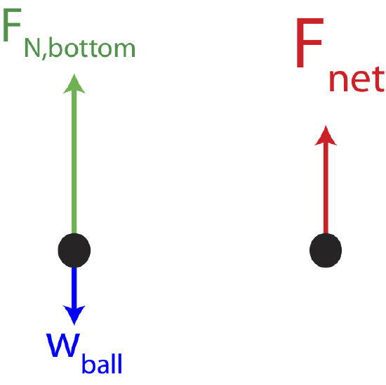
a) The force on the scale is the force by the ball on the scale, which is Newton's 3rd Law pair with the force by the scale on the ball, which is the normal force. Since the ball is moving in a circle it experiences centripetal acceleration that points toward the center of the circle. There are two forces present, gravity and the normal force by the track on the ball. At the bottom of the track, gravity points down and the normal force points up. Since the net force is up in the direction of centripetal acceleration, the normal force is greater than the weight of the ball. The force diagram at the bottom of the track is shown below, along with the net force.
Using equation for centripetal acceleration we find the net force at the bottom of the track is:
\[\sum F_y=F_N-mg=ma_c=m\frac{v^2}{R}\nonumber\]
Solving for the normal force we get:
\[F_N=mg+m\frac{v^2}{R}=(0.4kg)\Big(9.8 m/s^2+\frac{1.5^2 m^2/s^2}{0.8 m}\Big)=5.0 N\nonumber\]
Thus, the scale reads 5.0 N.
b) In this case since the circle is vertical and gravity always points down, the net force is not always toward the center. The normal force always points toward the center and contributes to centripetal acceleration, but the force of gravity acts along the direction of motion except at the top and at the bottom. As the ball goes from the bottom to the top, the ball slows down, and as it returns to the bottom it speeds us again. Thus, the speed is not constant.