
B24: Thin Film Interference


- Last updated
- Jan 16, 2023
- Save as PDF

( \newcommand{\kernel}{\mathrm{null}\,}\)
As the name and context imply, thin-film interference is another interference phenomenon involving light. Here’s the picture, as viewed from above:
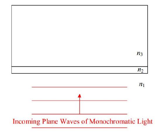
Involved are three transparent media: medium 1, medium 2, and medium 3, of index of refraction n1, n2, and n3, respectively. (In general, a medium is a substance, but, in this context, vacuum is also considered a medium. The index of refraction n of a medium is the ratio of the speed of light in vacuum to the speed of light in that medium.) The phenomenon occurs whether or not n1=n3, but, n2 must be different from n1 and n3. Medium 2 is the “thin film.” For thin-film interference to occur, the thickness of medium 2 must be on the order of the wavelength of the light. (The actual maximum thickness for which thin-film interference can occur depends on the coherence of the light.)
Here’s the deal: Under most circumstances, when light encounters a smooth interface between two transparent media, some of the light goes through (transmitted light) and some of the light bounces off (reflected light). In the thin-film arrangement of three transparent media depicted above, for certain thicknesses of the thin film (medium 2) all the light can be reflected, and, for certain other thicknesses, all the light can be transmitted. You see this phenomenon when looking at soap bubbles, and sometimes when looking at puddles in the road (when there is a thin layer of oil on top of the water). Humans take advantage of the phenomenon by putting a thin coating of a transparent substance on lenses such as camera lenses and binocular lenses, a layer of just the right thickness for maximum transmission.
Based on the situations in which it occurs, it should be clear that we do not need monochromatic light to make thin-film interference happen. However, I am going to discuss it in terms of monochromatic light to get the idea across. Once you understand it in terms of monochromatic light, you can apply it to white light (a mixture of all the visible frequencies) to answer questions such as, “What wavelength of incoming white light will experience maximum reflection?” The answer helps one understand the rainbow of colors you might see on the surface of a puddle in broad daylight. You put a clear layer of gasoline on top of a clear puddle of water and thin-film interference results in maximal constructive interference of the reflected light, at certain wavelengths.
Based on your experience with soap bubbles and puddle surfaces, you know that the light does not have to be normally incident upon the interface between transparent media in order for thin-film interference to occur. However, the analysis is easier for the case of normal incidence, so, in this chapter, I am going to limit our analysis to the case of normal incidence.
Here’s the gross idea: In going through a thin transparent film, light encounters two interfaces, the n1 abutting n2 interface, and, the n2 abutting n3 interface. At each interface, some of the light gets through and some is reflected. We can say all that we need to say about thin-film interference, just by talking about the reflected light. The thing is, light reflected off the second interface interferes with light reflected off the first interface. The reflected light can be thought of as being from two sources at two different locations, one source being the n1 abutting n2 interface, and the other being the n2 abutting n3 interface. But, there is a fixed phase difference between the light from the two sources because the light was originally part of one and the same source of incoming light. The light reflected from the second interface travels farther, to arrive back at the same backward position, than the light reflected from the first interface does. If you figure, that, when that extra distance is one wavelength, the interference of reflected light is constructive, and that, when that extra distance is half a wavelength, the interference of reflected light is destructive, then you’ve got the right idea, but, there are two “complications” that need to be taken into account.
The first complication has to do with phase reversal upon reflection. Consider a single interface (forget about the thin film for a moment) between two transparent medium. Assume light to be incident upon the interface. Call the index of refraction of the medium in which the light is initially traveling, n1, and call the index of refraction of the medium in which the transmitted light travels, n2. Experimentally we find that if n2>n1, then the reflected light is phase reversed, but, that if n2<n1, the reflected light experiences no phase change at all.
Regarding what we mean by phase reversal: Think of a crest of a wave hitting the interface. More specifically, let the electric field be oscillating along the vertical (into and out of the page in the diagram) so that at the instant under consideration, we have a forward-moving maximum upward-directed electric field vector at the location of the interface. An infinitesimal time dt later, we will find a forward-moving maximum-upward electric field vector at a point v2dt forward of the interface. If n2>n1 (phase reversal condition met), then, at the same instant in time (dt after the forward-moving maximum upward-directed electric field vector hits the interface) we have a maximum downward-directed electric field vector, traveling backward, at a point v1 dt behind the interface. This is what we mean by phase reversal. An incoming electric field vector pointing in one direction, bounces off the interface as an electric field vector pointing in the opposite direction. If there is no phase reversal, then, at the specified instant in time, we would have a maximum upward-directed electric field vector, traveling backward, at a pointv1dt behind the interface. With no phase reversal, an electric field vector pointing in one direction, bounces off the interface as an electric field vector pointing in the same direction.
Now back to the thin-film setup:
Recall that to get back to some specified point in space, light reflecting off the second interface (between medium 2 and medium 3) travels farther than the light reflecting off the first interface (between medium 1 and medium 2). Before, we hypothesized that if the path difference was a half a wavelength, the light from the two “sources” would interfere destructively, but, that if it was a full wavelength, the interference would be constructive. Now, if there is no phase reversal from either surface (because n2<n1 and n3<n2), or, if there is phase reversal from both surfaces (because n2>n1 and n3>n2) then our original hypothesis is still viable. But, if we have phase reversal at one of the interfaces but not the other (n2>n1 but n3<n2, or, n3>n2 but n2<n1), then the situation is reversed. A path difference of one wavelength would result in a crest interfering with a “crest that upon reflection turned into a trough” meaning that a path difference of one wavelength would result in destructive interference. And, a path difference of half a wavelength would result in a crest interfering with a “trough that upon reflection turned into a crest” meaning that a path difference of half a wavelength would result in constructive interference. Okay, we have addressed the phase reversal issue. We have one more complication to deal with. The thing is, the light that bounces off the second interface, not only travels a greater distance, but, it travels at a different speed while it is traveling that extra distance because it is in a different medium. Let’s see how this complication plays out.
The phenomenon holds true for every part of the wave. I focus the attention on crests, just because I find them easier to keep track of. For now, I also want to focus attention on the no-phase-reversal constructive interference case. Consider an instant when a crest of the forward traveling incoming wave hits the first interface. The crest of the transmitted wave travels through the interface, proceeds through the second medium at speed v2=c/n2, bounces off the interface with the third medium, and travels back through the second medium, completing its round trip (of distance two times the thickness of the second medium) through the second medium in time:
t2=2(thickness)v2
Now, while that is going on, the next crest from the incoming wave is traveling forward at speed v1=c/n1. It arrives at the same interface (between medium 1 and medium 2) at time
t1=λ1v1
where λ1 is the wavelength of the light while it is traveling in medium 1. (Remember, the source establishes the frequency of the light and that never changes, but, from v=λf, the wavelength depends on the speed of the wave in the medium in which the light is traveling.) For constructive interference (under no phase-reversal conditions), we must have
t1=t2
which, from the expressions for t1 and t2 above, can be written as:
λ1v1=2(thickness)v2
Substituting v1=λ1f and v2=λ2f yields:
λ1λ1f=2(thickness)λ2f
λ2=2(thickness)
I’m going to leave the result in this form because twice the thickness of the thin film is the path difference. So the equation is saying that, under no-phase-reversal conditions, there will be constructive interference of the light reflected from the two interfaces, when the wavelength that the light has in the material of which the thin film consists, is equal to the path difference. Of course, if the path difference is 2λ2,3λ2,4λ2, etc. we will also get constructive interference. We can write this as:
mλ2=2(thickness)(m=1,2,3,...)
where:
m is an integer,
λ2 is the in-the-thin-film wavelength of the light, and,
thickness is the thickness of the thin film.
This condition is also appropriate for the case of maximal constructive interference when phase reversal occurs at both interfaces. But, this condition yields completely destructive interference of reflected light when there is phase reversal at one interface but not the other.
The in-the-film wavelength λ2 of the light can be expressed most simply in terms of the wavelength λ1 of the light in the medium in which it is originally traveling, by setting the two expressions for the frequency equal to each other. From v1=λ1f we have f=v1/λ1. but from n1=c/v1 we have v1=c/n1. Replacing v1 in f=v1/λ1 with c/n1 yields f=cn1λ1. In a similar manner, we find that f can be expressed as f=cn2λ2. Setting the two expressions for f equal to each other yields:
cn1λ1=cn2λ2
which can be written as:
λ2=n1n2λ1
To get a maximum when we have phase reversal at one, and only one, interface, we need the path difference (twice the thickness) to be half a wavelength-in-the-film,
12λ2=2(thickness)
or that, plus, an integer number of full wavelengths-in-the-film:
(m+12)λ2=2(thickness)(m=1,2,3,...)
This is also the condition for completely destructive interference for the case of no phase reversal, or, phase reversal at both interfaces. This is exactly what we want for a camera lens that is to be used in air (n1=1.00). Consider a clear plastic medium of index of refraction n2=1.3. Now consider the wavelength that light from the middle of the visible spectrum (green light) would have in that medium. Put a coating of the plastic, one quarter as thick as that wavelength is long, on a lens made of glass having an index of refraction n3=1.5. (Note that we have phase reversal at both interfaces.) With that coating, the lens reflects none of the light of the specified wavelength that is normally incident on the lens (and a reduced amount of light of nearby wavelengths). That is, it transmits more of the light than it would without the coating. This is the desired effect.