28: Optical Depth
- Page ID
- 24374
\( \newcommand{\vecs}[1]{\overset { \scriptstyle \rightharpoonup} {\mathbf{#1}} } \)
\( \newcommand{\vecd}[1]{\overset{-\!-\!\rightharpoonup}{\vphantom{a}\smash {#1}}} \)
\( \newcommand{\dsum}{\displaystyle\sum\limits} \)
\( \newcommand{\dint}{\displaystyle\int\limits} \)
\( \newcommand{\dlim}{\displaystyle\lim\limits} \)
\( \newcommand{\id}{\mathrm{id}}\) \( \newcommand{\Span}{\mathrm{span}}\)
( \newcommand{\kernel}{\mathrm{null}\,}\) \( \newcommand{\range}{\mathrm{range}\,}\)
\( \newcommand{\RealPart}{\mathrm{Re}}\) \( \newcommand{\ImaginaryPart}{\mathrm{Im}}\)
\( \newcommand{\Argument}{\mathrm{Arg}}\) \( \newcommand{\norm}[1]{\| #1 \|}\)
\( \newcommand{\inner}[2]{\langle #1, #2 \rangle}\)
\( \newcommand{\Span}{\mathrm{span}}\)
\( \newcommand{\id}{\mathrm{id}}\)
\( \newcommand{\Span}{\mathrm{span}}\)
\( \newcommand{\kernel}{\mathrm{null}\,}\)
\( \newcommand{\range}{\mathrm{range}\,}\)
\( \newcommand{\RealPart}{\mathrm{Re}}\)
\( \newcommand{\ImaginaryPart}{\mathrm{Im}}\)
\( \newcommand{\Argument}{\mathrm{Arg}}\)
\( \newcommand{\norm}[1]{\| #1 \|}\)
\( \newcommand{\inner}[2]{\langle #1, #2 \rangle}\)
\( \newcommand{\Span}{\mathrm{span}}\) \( \newcommand{\AA}{\unicode[.8,0]{x212B}}\)
\( \newcommand{\vectorA}[1]{\vec{#1}} % arrow\)
\( \newcommand{\vectorAt}[1]{\vec{\text{#1}}} % arrow\)
\( \newcommand{\vectorB}[1]{\overset { \scriptstyle \rightharpoonup} {\mathbf{#1}} } \)
\( \newcommand{\vectorC}[1]{\textbf{#1}} \)
\( \newcommand{\vectorD}[1]{\overrightarrow{#1}} \)
\( \newcommand{\vectorDt}[1]{\overrightarrow{\text{#1}}} \)
\( \newcommand{\vectE}[1]{\overset{-\!-\!\rightharpoonup}{\vphantom{a}\smash{\mathbf {#1}}}} \)
\( \newcommand{\vecs}[1]{\overset { \scriptstyle \rightharpoonup} {\mathbf{#1}} } \)
\(\newcommand{\longvect}{\overrightarrow}\)
\( \newcommand{\vecd}[1]{\overset{-\!-\!\rightharpoonup}{\vphantom{a}\smash {#1}}} \)
\(\newcommand{\avec}{\mathbf a}\) \(\newcommand{\bvec}{\mathbf b}\) \(\newcommand{\cvec}{\mathbf c}\) \(\newcommand{\dvec}{\mathbf d}\) \(\newcommand{\dtil}{\widetilde{\mathbf d}}\) \(\newcommand{\evec}{\mathbf e}\) \(\newcommand{\fvec}{\mathbf f}\) \(\newcommand{\nvec}{\mathbf n}\) \(\newcommand{\pvec}{\mathbf p}\) \(\newcommand{\qvec}{\mathbf q}\) \(\newcommand{\svec}{\mathbf s}\) \(\newcommand{\tvec}{\mathbf t}\) \(\newcommand{\uvec}{\mathbf u}\) \(\newcommand{\vvec}{\mathbf v}\) \(\newcommand{\wvec}{\mathbf w}\) \(\newcommand{\xvec}{\mathbf x}\) \(\newcommand{\yvec}{\mathbf y}\) \(\newcommand{\zvec}{\mathbf z}\) \(\newcommand{\rvec}{\mathbf r}\) \(\newcommand{\mvec}{\mathbf m}\) \(\newcommand{\zerovec}{\mathbf 0}\) \(\newcommand{\onevec}{\mathbf 1}\) \(\newcommand{\real}{\mathbb R}\) \(\newcommand{\twovec}[2]{\left[\begin{array}{r}#1 \\ #2 \end{array}\right]}\) \(\newcommand{\ctwovec}[2]{\left[\begin{array}{c}#1 \\ #2 \end{array}\right]}\) \(\newcommand{\threevec}[3]{\left[\begin{array}{r}#1 \\ #2 \\ #3 \end{array}\right]}\) \(\newcommand{\cthreevec}[3]{\left[\begin{array}{c}#1 \\ #2 \\ #3 \end{array}\right]}\) \(\newcommand{\fourvec}[4]{\left[\begin{array}{r}#1 \\ #2 \\ #3 \\ #4 \end{array}\right]}\) \(\newcommand{\cfourvec}[4]{\left[\begin{array}{c}#1 \\ #2 \\ #3 \\ #4 \end{array}\right]}\) \(\newcommand{\fivevec}[5]{\left[\begin{array}{r}#1 \\ #2 \\ #3 \\ #4 \\ #5 \\ \end{array}\right]}\) \(\newcommand{\cfivevec}[5]{\left[\begin{array}{c}#1 \\ #2 \\ #3 \\ #4 \\ #5 \\ \end{array}\right]}\) \(\newcommand{\mattwo}[4]{\left[\begin{array}{rr}#1 \amp #2 \\ #3 \amp #4 \\ \end{array}\right]}\) \(\newcommand{\laspan}[1]{\text{Span}\{#1\}}\) \(\newcommand{\bcal}{\cal B}\) \(\newcommand{\ccal}{\cal C}\) \(\newcommand{\scal}{\cal S}\) \(\newcommand{\wcal}{\cal W}\) \(\newcommand{\ecal}{\cal E}\) \(\newcommand{\coords}[2]{\left\{#1\right\}_{#2}}\) \(\newcommand{\gray}[1]{\color{gray}{#1}}\) \(\newcommand{\lgray}[1]{\color{lightgray}{#1}}\) \(\newcommand{\rank}{\operatorname{rank}}\) \(\newcommand{\row}{\text{Row}}\) \(\newcommand{\col}{\text{Col}}\) \(\renewcommand{\row}{\text{Row}}\) \(\newcommand{\nul}{\text{Nul}}\) \(\newcommand{\var}{\text{Var}}\) \(\newcommand{\corr}{\text{corr}}\) \(\newcommand{\len}[1]{\left|#1\right|}\) \(\newcommand{\bbar}{\overline{\bvec}}\) \(\newcommand{\bhat}{\widehat{\bvec}}\) \(\newcommand{\bperp}{\bvec^\perp}\) \(\newcommand{\xhat}{\widehat{\xvec}}\) \(\newcommand{\vhat}{\widehat{\vvec}}\) \(\newcommand{\uhat}{\widehat{\uvec}}\) \(\newcommand{\what}{\widehat{\wvec}}\) \(\newcommand{\Sighat}{\widehat{\Sigma}}\) \(\newcommand{\lt}{<}\) \(\newcommand{\gt}{>}\) \(\newcommand{\amp}{&}\) \(\definecolor{fillinmathshade}{gray}{0.9}\)We know how to calculate the mean free path of an atom or ion in the atmosphere of the Sun. But what about a photon? It may pass right through an atom without interacting with it. So it won't be quite so easy to figure out just how far a photon will move before it is absorbed by or scatters off an atom.
However, if we put off the question of calculating the mean free path for a bit, we will find that it's not so hard to find a relationship between the distance a beam of light travels through some medium and the amount by which its intensity diminishes. Let's concentrate on that topic for today, and leave the details of the mean free path for later.
Intensity, mean free path, and opacity
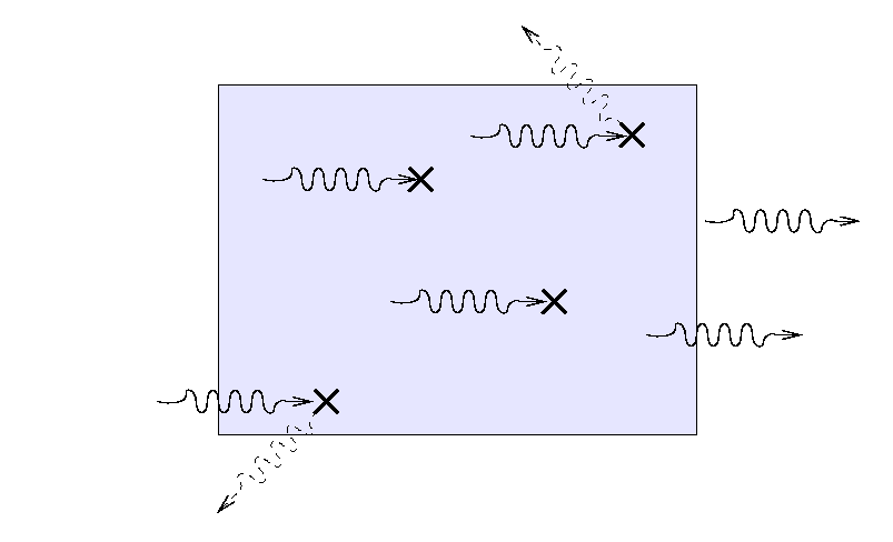
Suppose that a beam of light with some original intensity I0 runs into a slab of material.
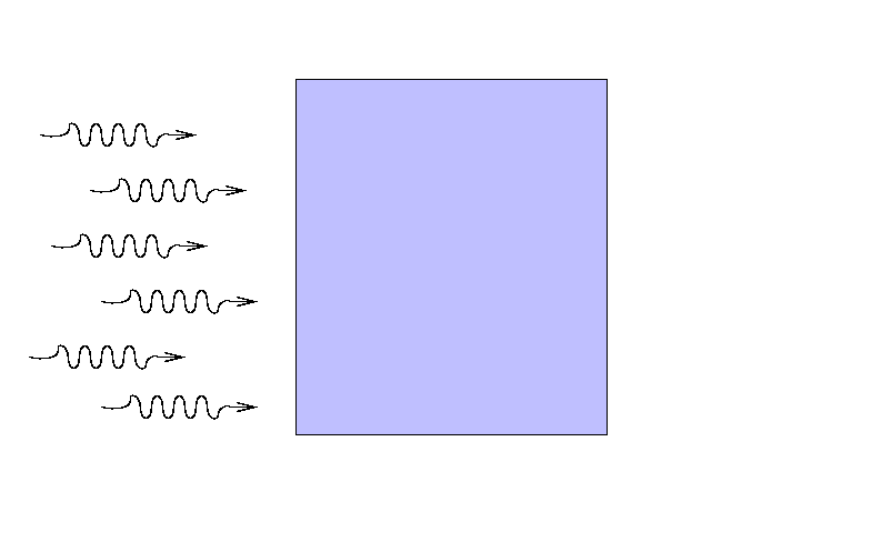
As the rays move through the material, some may be absorbed ...
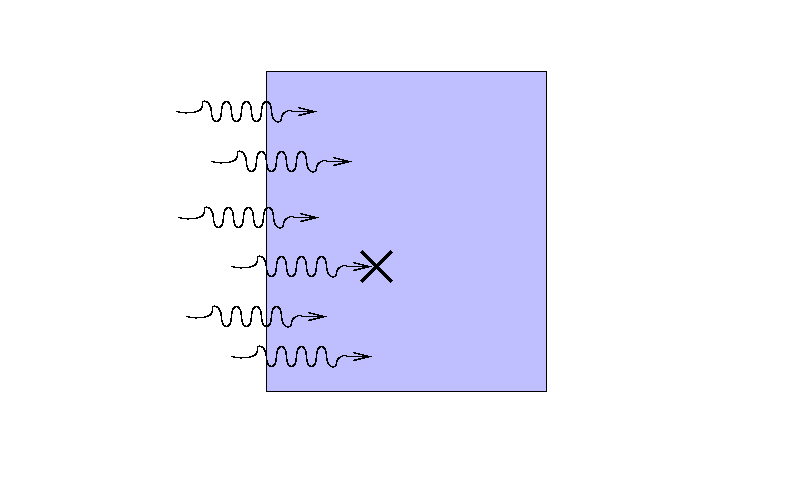
... or scattered ...
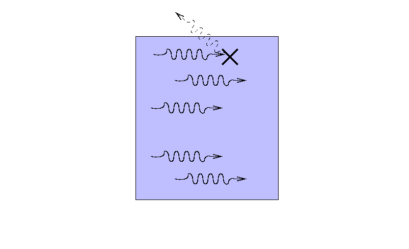
... so that only a fraction I reaches the other side.
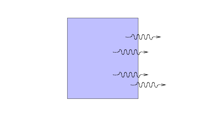
What is the ratio of the final intensity to the original intensity?
There are several factors which must affect the intensity in obvious ways:
- the greater the distance the beam travels, the more light will be removed from it
- the greater the density of material \(\mathbf{ρ}\), the more light will be scattered or absorbed
- the composition of the material -- some atoms are much more efficient at absorbing light than others
We can put all this together in mathematical form like so:
\[d I=-\kappa \rho I d s \nonumber \]
where \(\mathbf{I}\) is the incoming intensity of the light, \(\mathbf{dI}\) is the amount of light added to the beam (hence the negative sign), ds is the distance it travels, and ρ is the density of the material. The variable \(\mathbf{κ}\), called the opacity or absorption coefficient, serves two purposes: first, it's a constant of proportionality which serves to make the units match on both sides of the equation; second, it expresses the efficiency with which this particular sort of material (hydrogen, or helium, or electrons, or ...) absorbs and scatters light.
Exercise \(\PageIndex{1}\)
What are the units of opacity?
Note that we have chosen to define \(\mathbf{dI}\) as the amount of light ADDED to the beam, which may seem backwards. As long as we remember to include a negative sign, we'll be okay. It turns out that there are some special situations (none that will matter in this course) in which the sign is actually positive: by moving through a medium, the beam of light becomes MORE intense! Weird, huh? Yet you have seen examples of this "positive absorption" many times in the past few years.
Exercise \(\PageIndex{2}\)
Describe an everyday device which has a "negative opacity".
Opacity and the mean free path of a photon
Given our choice for defining opacity, via the small change in intensity as a function of distance traveled,
\[d I=-\kappa \rho I d s \nonumber \]
we need to integrate over the entire distance \(\mathbf{s}\) to find the final intensity in terms of the initial intensity. If the medium has uniform properties (density and opacity) everywhere, then this integral is easy:
\[\begin{aligned}\int \frac{d I}{I} &=-\int_{0}^{s} \kappa \rho d s \\\ln \left(I / I_{0}\right) &=-\kappa \rho \int_{0}^{s} d s \\&=-\kappa \rho s\end{aligned} \nonumber \]
Or, if we raise \(\mathbf{e}\) to the power of both sides to get rid of the natural logarithm,
\[\begin{aligned}\frac{I}{I_{0}} &=e^{-\kappa \rho s} \\&=e^{-s / \ell}\end{aligned} \nonumber \]
This seems pretty simple. The intensity of a light beam falls by a factor of \(\mathbf{1/e}\) for every distance \(\mathbf{\ell}\) it travels, where \(\mathbf{\ell}\) depends on the density and opacity.
Hmmm. That seems like a reasonable way to define a mean free path. Let's call \(\mathbf{\ell}\) the mean free path of a light ray.
It turns out to be quite a complicated process to determine the opacity of material in the outer layers of a typical star. We'll leave the details for another day. For now, let's just use one of the many, many compilations of opacity (as a function of composition, density, temperature, etc.) that one can find in the literature. The figure below shows opacity as a function of temperature for a sun-like star. The units are a little unusual: log10 of opacity on the vertical axis, and log10 of temperature in millions of Kelvin on the horizontal axis. The solid line corresponds to a density closest to the Sun's photosphere.
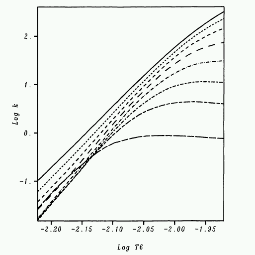
Exercise \(\PageIndex{3}\)
- What is the approximate opacity in the Sun's photosphere?
- What is the mean free path of a photon in the Sun's photosphere?
- How does the mfp of a photon compare to that of a hydrogen atom?
- How does the mfp of a photon compare to the scale height? Is the photosphere in local thermodynamic equilibrium?
Optical Depth
Consider a beam of light entering some slab of material. The slab might be relatively narrow,
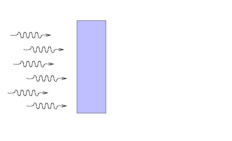
yet still block a considerable fraction of the light, if its atoms are densely packed and efficient at interacting with light.
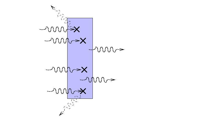
On the other hand, a much wider slab of material
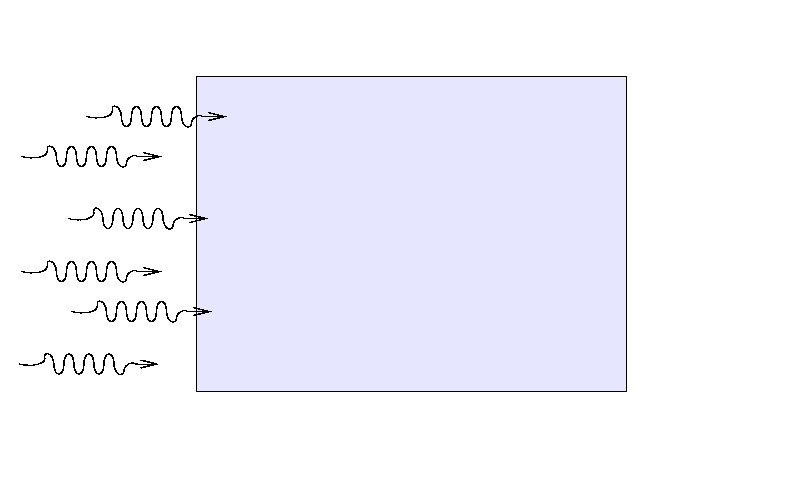
with a lower opacity and/or density might block exactly the same fraction of light,
If all we care about is the fraction of light which is blocked, or makes it through the slab, we might combine the three factors
- size
- density
- opacity
into a single value which expresses "ability to block light." Mathematically,
\[\begin{aligned}\frac{I}{I_{0}} &=e^{-\kappa \rho s} \\&=e^{-\tau}\end{aligned} \nonumber \]
We call this variable \(\mathbf{τ}\) the optical depth of the slab. Look carefully at the definition of optical depth -- it is exactly the same as "the number of mean free paths through the slab."
The optical depth turns out have several meanings. Consider, for example, light which must makes its way through some scattering medium. Suppose that the mean free path of the light is small compared to the thickness of the material, so that the light bounces many times before finally escaping. Note the location of the last bounce.
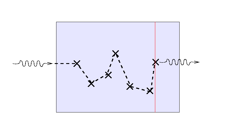
If we send a second light ray into the medium, it will follow a different path ...
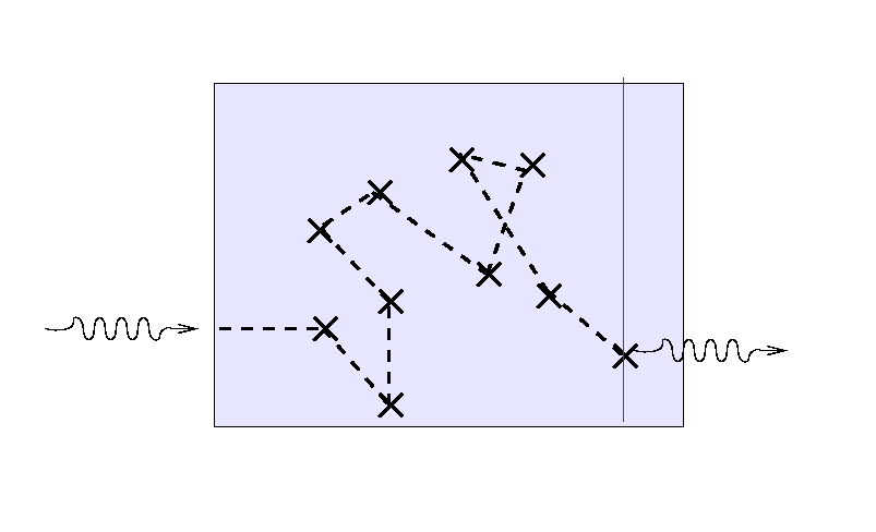
... and a third ray will again scatter randomly before finding its way out.
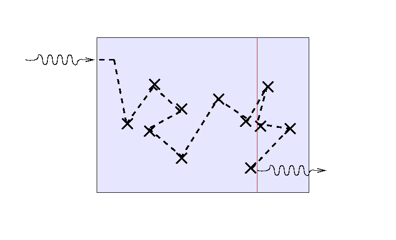
But note that the location of the final bounce tends to be roughly one mean free path, or one optical depth, from the outer edge of the medium. If we turn the situation around and ask, "How far can we see into the slab from the outside?"
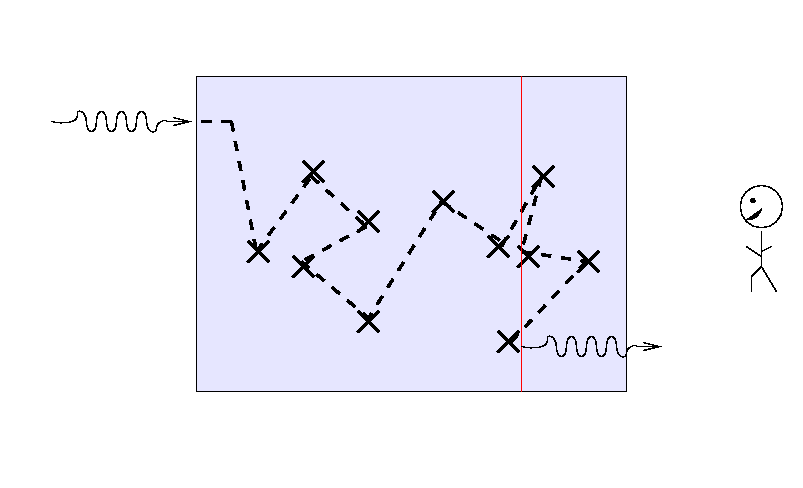
the answer turns out to be "about one mean free path", or, equivalently, "about one optical depth."
Exercise \(\PageIndex{4}\)
- Estimate the optical depth of the Earth's atmosphere; consider the view across a landscape from the top of a mountain. Perhaps these pictures will help:
- Dawn from Lick Observatory, on Mount Hamilton with San Jose in the distance.
- The San Francisco Bay looking north from San Francisco; you can see Alcatraz and the hills of Marin in the background.
- The Blue Ridge Mountains from a photo gallery run by Richard Saylor.
- Compare the optical depth of the Earth's atmosphere to that of the Sun's photosphere you calculated earlier.
- Now look at figure 9.10 in your textbook, which shows optical depth as a function of temperature. It turns out that one CAN extrapolate reasonably to lower temperatures and higher densities. Based on this figure, would you expect the optical depth of the Earth's atmosphere to be larger or smaller than that of the Sun's photosphere?
- Can you explain the reason for the apparent inconsistency?
The two extremes of optical depth
The overall optical depth of a cloud of gas is an important number. If tells us right away if the cloud falls into one of two useful regimes:
optically thin: \(\mathbf{\tau << 1}\)
If the gas is optically thin, then the chances are small that a photon will interact with a single particle ... and REALLY small that it will interact with more than one. We can safely ignore multiple scatterings or absorptions. In general terms, we can see right through the cloud.
Consider this example: suppose that you look at a typical portion of the Earth's atmosphere, which has opacity roughly κ = 0.0001 cm^2/g, density ρ = 0.001 g/cm^3, and a length of 1 km.
Exercise \(\PageIndex{5}\)
What is the optical depth of this gas? Send a beam of intensity I through the gas. What fraction of the light is blocked, and what fraction escapes? If you double the length of the sample, what happens to the fraction which is blocked? What happens to the fraction which escapes?
In the optically thin regime, the amount of extinction (absorption plus scattering) is simply related to the amount of material: double the amount of stuff, double the extinction. There is hope, then, that if we can measure the amount of light absorbed (or emitted) by the gas, we can calculate exactly how much gas there is.
optically thick: \(\mathbf{\tau >> 1}\)
If the gas is optically thick, then it is certain that a photon will interact many, many times with particles before it finally escapes from the cloud. Any photon entering the cloud will have its direction changed many times by collisions -- which means that its "output" direction has nothing to do with its "input" direction. In general terms, we can't see anything at all through the cloud: it is opaque.
Consider this example: suppose that you look at a typical portion of the atmosphere in downtown LA, which has opacity roughly κ = 0.1 cm^2/g, density ρ = 0.001 g/cm^3, and a length of 1 km.
Exercise \(\PageIndex{6}\)
What is the optical depth of this gas? Send a beam of intensity I through the gas. What fraction of the light is blocked, and what fraction escapes? If you double the length of the sample, what happens to the fraction which is blocked? What happens to the fraction which escapes?
You can't see through an optically thick medium; you can only see light emitted by the very outermost layers. Bummer.
But there is one convenient feature of optically thick materials: the spectrum of the light they emit is a blackbody spectrum, or very close to it.
Example: extinction in the Earth's atmosphere
Consider light rays from a particular star as they head towards a particular observer on the Earth's surface. As light makes its way through the Earth's atmosphere, some photons collide with atoms, molecules, water droplets, grains of dust, and other objects. These photons may be absorbed by the objects (in which case they cease to exist), or they may be scattered into a different direction. Either way, they no longer reach the observer on the ground. As a result, the observer detects fewer light rays from the star than he would have seen on an air-free planet. We call this dimming of stellar light extinction.
Clearly, the amount of extinction depends on how much air light rays must traverse. Astronomers have devised the term airmass method to describe this quantity: one airmass is the amount of air directly above an observer. So, if you are looking at a star at the zenith, you are looking through one airmass.
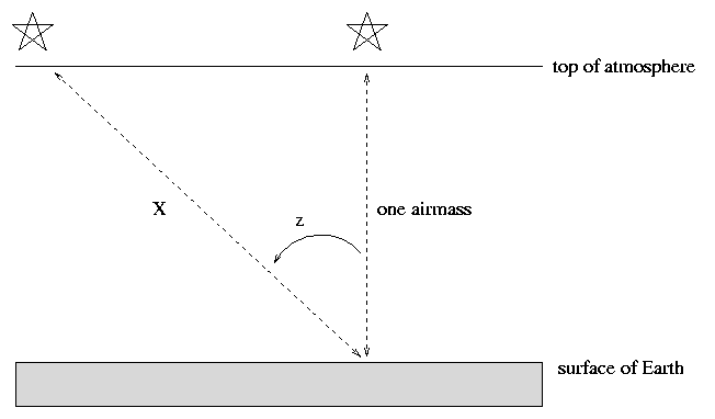
If, however, your target is some angular distance away from the zenith, indicated by the zenith angle z in the diagram above, then its light travels a longer distance through the Earth's atmosphere before it can reach you. To a reasonable approximation, one can consider the Earth and its atmosphere to be flat, parallel slabs. In that case, the distance light travels is
\[\text{airmass } X = \frac{\text{one airmass}}{\cos(z)} = (\text{one airmass}) * \sec(z) \nonumber \]
So, we can easily calculate how many airmasses light must traverse to reach us from an object at any given location in the sky.
One can calculate the relationship between airmass and extinction both theoretically and empirically. Theoretically, as long as the fraction of light lost is small, one can describe the intensity of light, \(\mathbf{I}\), as a function of airmass, \(\mathbf{X}\), as
\[I(X)=I_{0} e^{-c X} \nonumber \]
where \(\mathbf{I_0}\) is the original, exoatmospheric intensity of light from a star, and \(\mathbf{c}\) is some factor which depends on the properties of the atmosphere and the wavelength of light (blue is extinguished a lot, red is extinguished less).
If we measure brightness in magnitudes, then the relationship becomes conveniently linear:
\[m(X)=m_{0}+k X \nonumber \]
where \(\mathbf{m_0}\) is the exoatmospheric magnitude, and \(\mathbf{k}\) is again some constant which depends upon properties of the local atmosphere and the wavelength of light. We call the coefficient \(\mathbf{k}\) the "first order extinction coefficient."
Note that this k is not the same as the opacity κ, although the symbols look similar.
If one observes through the standard Johnson-Cousins UBVRI filters, one finds typical values
| passband | k |
|---|---|
| U | 0.6 |
| B | 0.4 |
| V | 0.2 |
| R | 0.1 |
| I | 0.08 |
Note that blue light is extinguished more than red light. This effect is most obvious when objects are just rising or setting, because then their light must pass through a very long stretch of atmosphere. That's why sunsets are red.

Image courtesy of National Network to End The War Against Iraq
The better the observing site, and the clearer the night, the smaller the extinction coefficient. If one is trying to correct for extinction, one must determine the first-order coefficient since the air changes from one night to the next; in fact, some astronomers solve for variations in extinction over the course of a night.
Below are measurements of the raw, instrumental magnitude of "Star A", observed for many hours at the RIT Observatory on UT July 27, 2001.
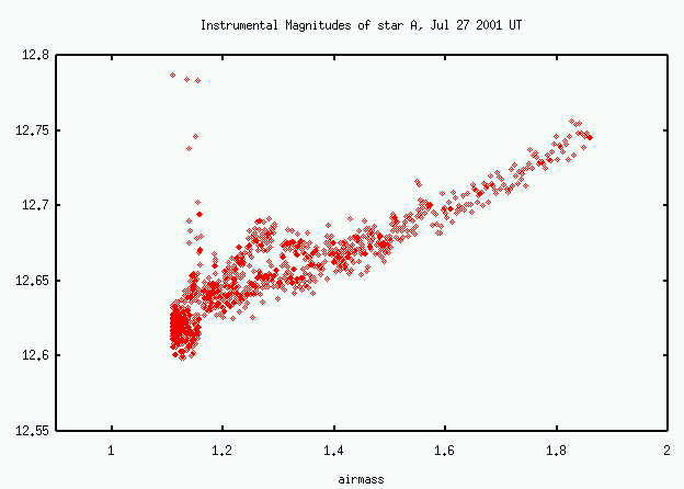
Exercise \(\PageIndex{7}\)
- What is the first-order extinction coefficient on this night?
- Is the Earth's atmosphere optically thin, optically thick, or somewhere in between?
- A star has true apparent magnitudes B = 12.0 and V = 11.5. What is the star's (B-V) color?
- The star is measured 20 degrees from the zenith at a typical sea-level observatory. What is the measured apparent magnitude in B and V?
- What is the measured (B-V) color?
The difference between the true (B-V) color of a star, and its measured (B-V) color, is sometimes called the reddening, and denoted E(B-V).
Exercise \(\PageIndex{8}\)
Using the typical extinction coefficients given in the table above, find a relationship between the change in (B-V) color of a star and the change in its V-band magnitude. Express this as an equation with E(B-V) on the left hand side, and the (B-V) color on the right hand side.
Extinction in the Milky Way's disk
The disk of our Milky Way galaxy contains gas and dust, and, as a result, it scatters and absorbs light passing through it. We can explain very roughly the large-scale variation in extinction with a very simple model of our galaxy: a uniform disk plus a spherical bulge.
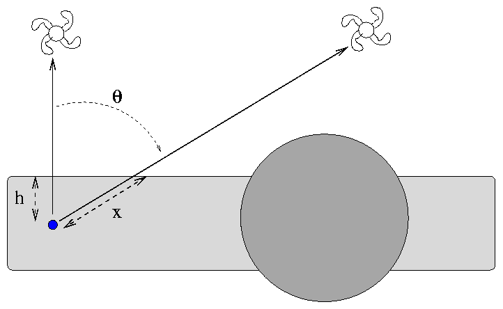
The Earth sits (very nearly) in the middle of the disk, halfway between the top and bottom. The amount of material through which light must pass to reach the Earth depends on the angle of its source from the normal to the plane. To a very, very rough approximation, the extinction in the B-band is around 0.10-0.20 magnitudes in the direction perpendicular to the plane.
Exercise \(\PageIndex{9}\)
Galaxy A is located directly above the plane of the Milky Way, at galactic latitude b = 90 degrees. Galaxy B is located at b = 60 degrees.
- What is the ratio of the distance x to the distance h?
- If the light from galaxy A suffers 0.20 magnitudes of extinction due to the Milky Way, how much does galaxy B suffer?
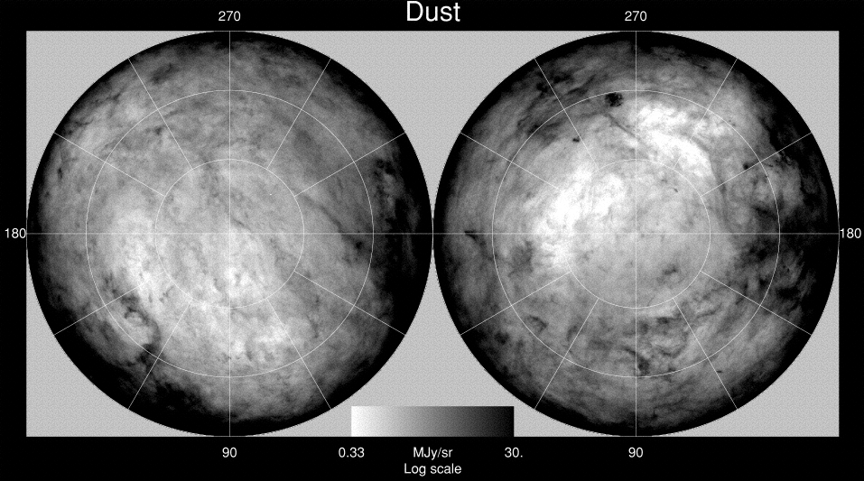
The real Milky Way is much, much more complex than our simple little model. Here's a full-sky map of distribution of dusty gas over the entire sky (in galactic coordinates, so that the plane of the Milky Way runs around the edge of both pictures); black areas are full of dust and extinction, white areas are dust-free and transparent.
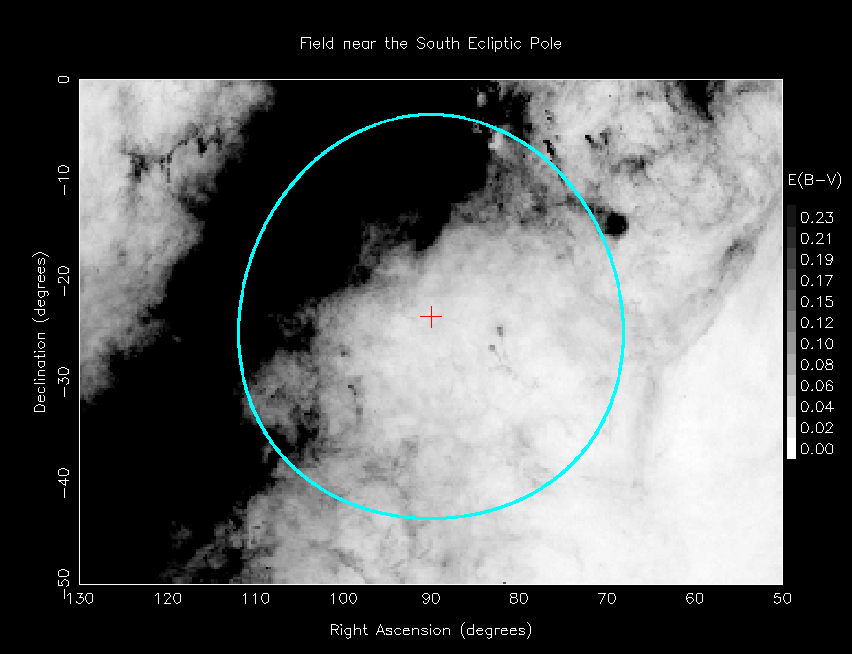
For quantitative view, look at this map of reddening in the vicinity of the southern ecliptic pole. That's the plane of the galaxy crossing the left side of the picture.
For more information
- "Radiative atomic Rosseland mean opacity tables", by Rogers and Iglesias, provides lots and lots of values of opacity for various temperatures and chemical compositions.
- The galactic extinction of extragalactic objects. I - The csc B law and the extinction coefficient by deVaucouleurs and Buta, goes into more detail of the classic model of galactic extinction than you probably want to know.
- The classic paper by Schlegel, Finkbeiner and Davis (1998) which provides a map of estimated extinction in our galaxy, based on the infrared emission by dusty clouds.


