
18.3: Generalized Lever Law
- Page ID
- 24538
\( \newcommand{\vecs}[1]{\overset { \scriptstyle \rightharpoonup} {\mathbf{#1}} } \)
\( \newcommand{\vecd}[1]{\overset{-\!-\!\rightharpoonup}{\vphantom{a}\smash {#1}}} \)
\( \newcommand{\dsum}{\displaystyle\sum\limits} \)
\( \newcommand{\dint}{\displaystyle\int\limits} \)
\( \newcommand{\dlim}{\displaystyle\lim\limits} \)
\( \newcommand{\id}{\mathrm{id}}\) \( \newcommand{\Span}{\mathrm{span}}\)
( \newcommand{\kernel}{\mathrm{null}\,}\) \( \newcommand{\range}{\mathrm{range}\,}\)
\( \newcommand{\RealPart}{\mathrm{Re}}\) \( \newcommand{\ImaginaryPart}{\mathrm{Im}}\)
\( \newcommand{\Argument}{\mathrm{Arg}}\) \( \newcommand{\norm}[1]{\| #1 \|}\)
\( \newcommand{\inner}[2]{\langle #1, #2 \rangle}\)
\( \newcommand{\Span}{\mathrm{span}}\)
\( \newcommand{\id}{\mathrm{id}}\)
\( \newcommand{\Span}{\mathrm{span}}\)
\( \newcommand{\kernel}{\mathrm{null}\,}\)
\( \newcommand{\range}{\mathrm{range}\,}\)
\( \newcommand{\RealPart}{\mathrm{Re}}\)
\( \newcommand{\ImaginaryPart}{\mathrm{Im}}\)
\( \newcommand{\Argument}{\mathrm{Arg}}\)
\( \newcommand{\norm}[1]{\| #1 \|}\)
\( \newcommand{\inner}[2]{\langle #1, #2 \rangle}\)
\( \newcommand{\Span}{\mathrm{span}}\) \( \newcommand{\AA}{\unicode[.8,0]{x212B}}\)
\( \newcommand{\vectorA}[1]{\vec{#1}} % arrow\)
\( \newcommand{\vectorAt}[1]{\vec{\text{#1}}} % arrow\)
\( \newcommand{\vectorB}[1]{\overset { \scriptstyle \rightharpoonup} {\mathbf{#1}} } \)
\( \newcommand{\vectorC}[1]{\textbf{#1}} \)
\( \newcommand{\vectorD}[1]{\overrightarrow{#1}} \)
\( \newcommand{\vectorDt}[1]{\overrightarrow{\text{#1}}} \)
\( \newcommand{\vectE}[1]{\overset{-\!-\!\rightharpoonup}{\vphantom{a}\smash{\mathbf {#1}}}} \)
\( \newcommand{\vecs}[1]{\overset { \scriptstyle \rightharpoonup} {\mathbf{#1}} } \)
\(\newcommand{\longvect}{\overrightarrow}\)
\( \newcommand{\vecd}[1]{\overset{-\!-\!\rightharpoonup}{\vphantom{a}\smash {#1}}} \)
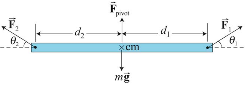
\(\newcommand{\avec}{\mathbf a}\) \(\newcommand{\bvec}{\mathbf b}\) \(\newcommand{\cvec}{\mathbf c}\) \(\newcommand{\dvec}{\mathbf d}\) \(\newcommand{\dtil}{\widetilde{\mathbf d}}\) \(\newcommand{\evec}{\mathbf e}\) \(\newcommand{\fvec}{\mathbf f}\) \(\newcommand{\nvec}{\mathbf n}\) \(\newcommand{\pvec}{\mathbf p}\) \(\newcommand{\qvec}{\mathbf q}\) \(\newcommand{\svec}{\mathbf s}\) \(\newcommand{\tvec}{\mathbf t}\) \(\newcommand{\uvec}{\mathbf u}\) \(\newcommand{\vvec}{\mathbf v}\) \(\newcommand{\wvec}{\mathbf w}\) \(\newcommand{\xvec}{\mathbf x}\) \(\newcommand{\yvec}{\mathbf y}\) \(\newcommand{\zvec}{\mathbf z}\) \(\newcommand{\rvec}{\mathbf r}\) \(\newcommand{\mvec}{\mathbf m}\) \(\newcommand{\zerovec}{\mathbf 0}\) \(\newcommand{\onevec}{\mathbf 1}\) \(\newcommand{\real}{\mathbb R}\) \(\newcommand{\twovec}[2]{\left[\begin{array}{r}#1 \\ #2 \end{array}\right]}\) \(\newcommand{\ctwovec}[2]{\left[\begin{array}{c}#1 \\ #2 \end{array}\right]}\) \(\newcommand{\threevec}[3]{\left[\begin{array}{r}#1 \\ #2 \\ #3 \end{array}\right]}\) \(\newcommand{\cthreevec}[3]{\left[\begin{array}{c}#1 \\ #2 \\ #3 \end{array}\right]}\) \(\newcommand{\fourvec}[4]{\left[\begin{array}{r}#1 \\ #2 \\ #3 \\ #4 \end{array}\right]}\) \(\newcommand{\cfourvec}[4]{\left[\begin{array}{c}#1 \\ #2 \\ #3 \\ #4 \end{array}\right]}\) \(\newcommand{\fivevec}[5]{\left[\begin{array}{r}#1 \\ #2 \\ #3 \\ #4 \\ #5 \\ \end{array}\right]}\) \(\newcommand{\cfivevec}[5]{\left[\begin{array}{c}#1 \\ #2 \\ #3 \\ #4 \\ #5 \\ \end{array}\right]}\) \(\newcommand{\mattwo}[4]{\left[\begin{array}{rr}#1 \amp #2 \\ #3 \amp #4 \\ \end{array}\right]}\) \(\newcommand{\laspan}[1]{\text{Span}\{#1\}}\) \(\newcommand{\bcal}{\cal B}\) \(\newcommand{\ccal}{\cal C}\) \(\newcommand{\scal}{\cal S}\) \(\newcommand{\wcal}{\cal W}\) \(\newcommand{\ecal}{\cal E}\) \(\newcommand{\coords}[2]{\left\{#1\right\}_{#2}}\) \(\newcommand{\gray}[1]{\color{gray}{#1}}\) \(\newcommand{\lgray}[1]{\color{lightgray}{#1}}\) \(\newcommand{\rank}{\operatorname{rank}}\) \(\newcommand{\row}{\text{Row}}\) \(\newcommand{\col}{\text{Col}}\) \(\renewcommand{\row}{\text{Row}}\) \(\newcommand{\nul}{\text{Nul}}\) \(\newcommand{\var}{\text{Var}}\) \(\newcommand{\corr}{\text{corr}}\) \(\newcommand{\len}[1]{\left|#1\right|}\) \(\newcommand{\bbar}{\overline{\bvec}}\) \(\newcommand{\bhat}{\widehat{\bvec}}\) \(\newcommand{\bperp}{\bvec^\perp}\) \(\newcommand{\xhat}{\widehat{\xvec}}\) \(\newcommand{\vhat}{\widehat{\vvec}}\) \(\newcommand{\uhat}{\widehat{\uvec}}\) \(\newcommand{\what}{\widehat{\wvec}}\) \(\newcommand{\Sighat}{\widehat{\Sigma}}\) \(\newcommand{\lt}{<}\) \(\newcommand{\gt}{>}\) \(\newcommand{\amp}{&}\) \(\definecolor{fillinmathshade}{gray}{0.9}\)We can extend the Lever Law to the case in which two external forces \(\overrightarrow{\mathbf{F}}_{1} \text { and } \overrightarrow{\mathbf{F}}_{2}\) are acting on the pivoted beam at angles \(\theta_{1} \text { and } \theta_{2}\) with respect to the horizontal as shown in the Figure 18.4. Throughout this discussion the angles will be limited to the range \(\left[0 \leq \theta_{1}, \theta_{2} \leq \pi\right]\). We shall again neglect the thickness of the beam and take the pivot point to be the center of mass.
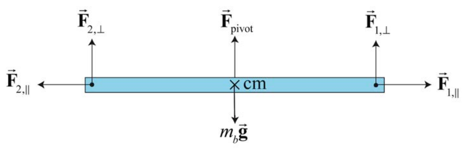
The forces \(\overrightarrow{\mathbf{F}}_{1} \text { and } \overrightarrow{\mathbf{F}}_{2}\) can be decomposed into separate vectors components respectively \(\left(\overrightarrow{\mathbf{F}}_{1, \|}, \overrightarrow{\mathbf{F}}_{1, \perp}\right) \text { and }\left(\overrightarrow{\mathbf{F}}_{2, \|}, \overrightarrow{\mathbf{F}}_{2, \perp}\right)\), where \(\overrightarrow{\mathbf{F}}_{1, \|} \text { and } \overrightarrow{\mathbf{F}}_{2, \|}\) are the horizontal vector projections of the two forces with respect to the direction formed by the length of the beam, and \(\overrightarrow{\mathbf{F}}_{1, \perp}\) and \(\overrightarrow{\mathbf{F}}_{2, \perp}\) are the perpendicular vector projections respectively to the beam (Figure 18.5), with
\[\overrightarrow{\mathbf{F}}_{1}=\overrightarrow{\mathbf{F}}_{1, \|}+\overrightarrow{\mathbf{F}}_{1, \perp} \nonumber \]
\[\overrightarrow{\mathbf{F}}_{2}=\overrightarrow{\mathbf{F}}_{2, \|}+\overrightarrow{\mathbf{F}}_{2, \perp} \nonumber \]
The horizontal components of the forces are
\[F_{1, \|}=F_{1} \cos \theta_{1} \nonumber \]
\[F_{2, \|}=-F_{2} \cos \theta_{2} \nonumber \]
where our choice of positive horizontal direction is to the right. Neither horizontal force component contributes to possible rotational motion of the beam. The sum of these horizontal forces must be zero,
\[F_{1} \cos \theta_{1}-F_{2} \cos \theta_{2}=0 \nonumber \]
The perpendicular component forces are
\[F_{1, \perp}=F_{1} \sin \theta_{1} \nonumber \]
\[F_{2, \perp}=F_{2} \sin \theta_{2} \nonumber \]
where the positive vertical direction is upwards. The perpendicular components of the forces must also sum to zero,
\[F_{\text {pivot }}-m_{b} g+F_{1} \sin \theta_{1}+F_{2} \sin \theta_{2}=0 \nonumber \]
Only the vertical components \(F_{1, \perp} \text { and } F_{2, \perp}\) of the external forces are involved in the lever law (but the horizontal components must balance, as in Equation (18.3.5), for equilibrium). Then the Lever Law can be extended as follows.
Generalized Lever Law A beam of length l is balanced on a pivot point that is placed directly beneath the center of mass of the beam. Suppose a force \(\overrightarrow{\mathbf{F}}_{1}\) acts on the beam a distance \(d_{1}\) to the right of the pivot point. A second force \(\overrightarrow{\mathbf{F}}_{2}\) acts on the beam a distance \(d_{2}\) to the left of the pivot point. The beam will remain in static equilibrium if the following two conditions are satisfied:
1) The total force on the beam is zero,
2) The product of the magnitude of the perpendicular component of the force with the distance to the pivot is the same for each force,
\[d_{1}\left|F_{1, \perp}\right|=d_{2}\left|F_{2, \perp}\right| \nonumber \]
The Generalized Lever Law can be stated in an equivalent form,
\[d_{1} F_{1} \sin \theta_{1}=d_{2} F_{2} \sin \theta_{2} \nonumber \]
We shall now show that the generalized lever law can be reinterpreted as the statement that the vector sum of the torques about the pivot point \(S\) is zero when there are just two forces \(\overrightarrow{\mathbf{F}}_{1} \text { and } \overrightarrow{\mathbf{F}}_{2}\) acting on our beam as shown in Figure 18.6.
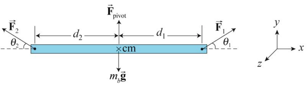
Let’s choose the positive z -direction to point out of the plane of the page then torque pointing out of the page will have a positive z -component of torque (counterclockwise rotations are positive). From our definition of torque about the pivot point, the magnitude of torque due to force \(\overrightarrow{\mathbf{F}}_{1}\) is given by
\[\tau_{S, 1}=d_{1} F_{1} \sin \theta_{1} \nonumber \]
From the right hand rule this is out of the page (in the counterclockwise direction) so the component of the torque is positive, hence,
\[\left(\tau_{S, 1}\right)_{z}=d_{1} F_{1} \sin \theta_{1} \nonumber \]
The torque due to \(\overrightarrow{\mathbf{F}}_{2}\) about the pivot point is into the page (the clockwise direction) and the component of the torque is negative and given by
\[\left(\tau_{S, 2}\right)_{z}=-d_{2} F_{2} \sin \theta_{2} \nonumber \]
The z -component of the torque is the sum of the z -components of the individual torques and is zero,
\[\left(\tau_{S, \text { total }}\right)_{z}=\left(\tau_{S, 1}\right)_{z}+\left(\tau_{S, 2}\right)_{z}=d_{1} F_{1} \sin \theta_{1}-d_{2} F_{2} \sin \theta_{2}=0 \nonumber \]
which is equivalent to the Generalized Lever Law, Equation (18.3.10),
\[d_{1} F_{1} \sin \theta_{1}=d_{2} F_{2} \sin \theta_{2} \nonumber \]