Physics LibreTexts

27.3: Young’s Double Slit Experiment

  • Page ID
    2742
  • \( \newcommand{\vecs}[1]{\overset { \scriptstyle \rightharpoonup} {\mathbf{#1}} } \) \( \newcommand{\vecd}[1]{\overset{-\!-\!\rightharpoonup}{\vphantom{a}\smash {#1}}} \)\(\newcommand{\id}{\mathrm{id}}\) \( \newcommand{\Span}{\mathrm{span}}\) \( \newcommand{\kernel}{\mathrm{null}\,}\) \( \newcommand{\range}{\mathrm{range}\,}\) \( \newcommand{\RealPart}{\mathrm{Re}}\) \( \newcommand{\ImaginaryPart}{\mathrm{Im}}\) \( \newcommand{\Argument}{\mathrm{Arg}}\) \( \newcommand{\norm}[1]{\| #1 \|}\) \( \newcommand{\inner}[2]{\langle #1, #2 \rangle}\) \( \newcommand{\Span}{\mathrm{span}}\) \(\newcommand{\id}{\mathrm{id}}\) \( \newcommand{\Span}{\mathrm{span}}\) \( \newcommand{\kernel}{\mathrm{null}\,}\) \( \newcommand{\range}{\mathrm{range}\,}\) \( \newcommand{\RealPart}{\mathrm{Re}}\) \( \newcommand{\ImaginaryPart}{\mathrm{Im}}\) \( \newcommand{\Argument}{\mathrm{Arg}}\) \( \newcommand{\norm}[1]{\| #1 \|}\) \( \newcommand{\inner}[2]{\langle #1, #2 \rangle}\) \( \newcommand{\Span}{\mathrm{span}}\)\(\newcommand{\AA}{\unicode[.8,0]{x212B}}\)

    Learning Objectives

    By the end of this section, you will be able to:

    • Explain the phenomena of interference.
    • Define constructive interference for a double slit and destructive interference for a double slit.

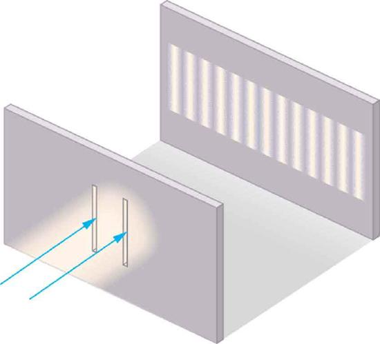
    Although Christiaan Huygens thought that light was a wave, Isaac Newton did not. Newton felt that there were other explanations for color, and for the interference and diffraction effects that were observable at the time. Owing to Newton’s tremendous stature, his view generally prevailed. The fact that Huygens’s principle worked was not considered evidence that was direct enough to prove that light is a wave. The acceptance of the wave character of light came many years later when, in 1801, the English physicist and physician Thomas Young (1773–1829) did his now-classic double slit experiment (Figure \(\PageIndex{1}\)).

    A beam of light strikes a wall through which a pair of vertical slits is cut. On the other side of the wall, another wall shows a pattern of equally spaced vertical lines of light that are of the same height as the slit.
    Figure \(\PageIndex{1}\): Young’s double slit experiment. Here pure-wavelength light sent through a pair of vertical slits is diffracted into a pattern on the screen of numerous vertical lines spread out horizontally. Without diffraction and interference, the light would simply make two lines on the screen.

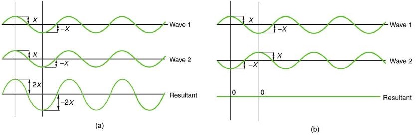
    Why do we not ordinarily observe wave behavior for light, such as observed in Young’s double slit experiment? First, light must interact with something small, such as the closely spaced slits used by Young, to show pronounced wave effects. Furthermore, Young first passed light from a single source (the Sun) through a single slit to make the light somewhat coherent. By coherent, we mean waves are in phase or have a definite phase relationship. Incoherent means the waves have random phase relationships. Why did Young then pass the light through a double slit? The answer to this question is that two slits provide two coherent light sources that then interfere constructively or destructively. Young used sunlight, where each wavelength forms its own pattern, making the effect more difficult to see. We illustrate the double slit experiment with monochromatic (single \(\lambda\)) light to clarify the effect. Figure \(\PageIndex{2}\) shows the pure constructive and destructive interference of two waves having the same wavelength and amplitude.

    Figure a shows three sine waves with the same wavelength arranged one above the other. The peaks and troughs of each wave are aligned with those of the other waves. The top two waves are labeled wave one and wave two and the bottom wave is labeled resultant. The amplitude of waves one and two are labeled x and the amplitude of the resultant wave is labeled two x. Figure b shows a similar situation, except that the peaks of wave two now align with the troughs of wave one. The resultant wave is now a straight horizontal line on the x axis; that is, the line y equals zero.
    Figure \(\PageIndex{2}\): The amplitudes of waves add. (a) Pure constructive interference is obtained when identical waves are in phase. (b) Pure destructive interference occurs when identical waves are exactly out of phase, or shifted by half a wavelength.

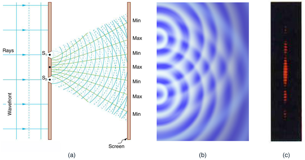
    When light passes through narrow slits, it is diffracted into semicircular waves, as shown in Figure \(\PageIndex{3a}\). Pure constructive interference occurs where the waves are crest to crest or trough to trough. Pure destructive interference occurs where they are crest to trough. The light must fall on a screen and be scattered into our eyes for us to see the pattern. An analogous pattern for water waves is shown in Figure \(\PageIndex{3b}\). Note that regions of constructive and destructive interference move out from the slits at well-defined angles to the original beam. These angles depend on wavelength and the distance between the slits, as we shall see below.

    The figure contains three parts. The first part is a drawing that shows parallel wavefronts approaching a wall from the left. Crests are shown as continuous lines, and troughs are shown as dotted lines. Two light rays pass through small slits in the wall and emerge in a fan-like pattern from two slits. These lines fan out to the right until they hit the right-hand wall. The points where these fan lines hit the right-hand wall are alternately labeled min and max. The min points correspond to lines that connect the overlapping crests and troughs, and the max points correspond to the lines that connect the overlapping crests. The second drawing is a view from above of a pool of water with semicircular wavefronts emanating from two points on the left side of the pool that are arranged one above the other. These semicircular waves overlap with each other and form a pattern much like the pattern formed by the arcs in the first image.  The third drawing shows a vertical dotted line, with some dots appearing brighter than other dots. The brightness pattern is symmetric about the midpoint of this line. The dots near the midpoint are the brightest. As you move from the midpoint up, or down, the dots become progressively dimmer until there seems to be a dot missing. If you progress still farther from the midpoint, the dots appear again and get brighter, but are much less bright than the central dots. If you progress still farther from the midpoint, the dots get dimmer again and then disappear again, which is where the dotted line stops.
    Figure \(\PageIndex{3}\): Double slits produce two coherent sources of waves that interfere. (a) Light spreads out (diffracts) from each slit, because the slits are narrow. These waves overlap and interfere constructively (bright lines) and destructively (dark regions). We can only see this if the light falls onto a screen and is scattered into our eyes. (b) Double slit interference pattern for water waves are nearly identical to that for light. Wave action is greatest in regions of constructive interference and least in regions of destructive interference. (c) When light that has passed through double slits falls on a screen, we see a pattern such as this. (credit: PASCO)

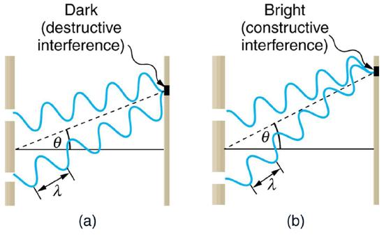
    To understand the double slit interference pattern, we consider how two waves travel from the slits to the screen, as illustrated in Figure \(\PageIndex{4}\). Each slit is a different distance from a given point on the screen. Thus different numbers of wavelengths fit into each path. Waves start out from the slits in phase (crest to crest), but they may end up out of phase (crest to trough) at the screen if the paths differ in length by half a wavelength, interfering destructively as shown in Figure \(\PageIndex{4a}\). If the paths differ by a whole wavelength, then the waves arrive in phase (crest to crest) at the screen, interfering constructively as shown in Figure \(\PageIndex{4b}\). More generally, if the paths taken by the two waves differ by any half-integral number of wavelengths [ \( \left( 1/2 \right) \lambda , \left(3/2 \right) \lambda , \left( 5/2 \right) \lambda,\) etc.], then destructive interference occurs. Similarly, if the paths taken by the two waves differ by any integral number of wavelengths (\( \lambda , 2\lambda , 3\lambda \), etc.), then constructive interference occurs.

    Both parts of the figure show a schematic of a double slit experiment. Two waves, each of which is emitted from a different slit, propagate from the slits to the screen. In the first schematic, when the waves meet on the screen, one of the waves is at a maximum whereas the other is at a minimum. This schematic is labeled dark (destructive interference). In the second schematic, when the waves meet on the screen, both waves are at a minimum.. This schematic is labeled bright (constructive interference).
    Figure \(\PageIndex{4}\): Waves follow different paths from the slits to a common point on a screen. (a) Destructive interference occurs here, because one path is a half wavelength longer than the other. The waves start in phase but arrive out of phase. (b) Constructive interference occurs here because one path is a whole wavelength longer than the other. The waves start out and arrive in phase.

    TAKE-HOME EXPERIMENT: USING FINGERS AS SLITS

    Look at a light, such as a street lamp or incandescent bulb, through the narrow gap between two fingers held close together. What type of pattern do you see? How does it change when you allow the fingers to move a little farther apart? Is it more distinct for a monochromatic source, such as the yellow light from a sodium vapor lamp, than for an incandescent bulb?
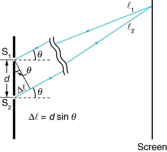
    Figure \(\PageIndex{5}\) shows how to determine the path length difference for waves traveling from two slits to a common point on a screen. If the screen is a large distance away compared with the distance between the slits, then the angle \(\theta\) between the path and a line from the slits to the screen is nearly the same for each path. The difference between the paths is shown in the figure; simple trigonometry shows it to be \(d \sin{\theta}\), where \(d\) is the distance between the slits. To obtain constructive interference for a double slit, the path length difference must be an integral multiple of the wavelength, or

    \[d\sin{\theta} = m \lambda, ~for~ m=0,1,-1,2,-2 ... \left( constructive \right). \label{27.4.1}\]

    Similarly, to obtain destructive interference for a double slit, the path length difference must be a half-integral multiple of the wavelength, or

    \[d \sin{\theta} = \left( m + \frac{1}{2} \right) \lambda, ~for~ m=0,1,-1,2,-2 ... \left( destructive \right). \label{27.4.2}\]

    where \(\lambda\) is the wavelength of the light, \(d\) is the distance between slits, and \(\theta\) is the angle from the original direction of the beam as discussed above. We call \(m\) the order of the interference. For example, \(m=4\) is fourth-order interference.

    The figure is a schematic of a double slit experiment, with the scale of the slits enlarged to show the detail. The two slits are on the left, and the screen is on the right. The slits are represented by a thick vertical line with two gaps cut through it a distance d apart. Two rays, one from each slit, angle up and to the right at an angle theta above the horizontal. At the screen, these rays are shown to converge at a common point. The ray from the upper slit is labeled l sub one, and the ray from the lower slit is labeled l sub two. At the slits, a right triangle is drawn, with the thick line between the slits forming the hypotenuse. The hypotenuse is labeled d, which is the distance between the slits. A short piece of the ray from the lower slit is labeled delta l and forms the short side of the right triangle. The long side of the right triangle is formed by a line segment that goes downward and to the right from the upper slit to the lower ray. This line segment is perpendicular to the lower ray, and the angle it makes with the hypotenuse is labeled theta. Beneath this triangle is the formula delta l equals d sine theta.
    Figure \(\PageIndex{5}\): The paths from each slit to a common point on the screen differ by an amount \(d\sin{\theta}\), assuming the distance to the screen is much greater than the distance between slits (not to scale here).

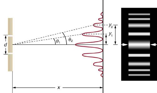
    The equations for double slit interference imply that a series of bright and dark lines are formed. For vertical slits, the light spreads out horizontally on either side of the incident beam into a pattern called interference fringes, illustrated in Figure \(\PageIndex{6}\). The intensity of the bright fringes falls off on either side, being brightest at the center. The closer the slits are, the more is the spreading of the bright fringes. We can see this by examining the Equation \ref{27.4.1}.

    For fixed \(\lambda\) and \(m\), the smaller \(d\) is, the larger \(\theta\) must be, since \(\sin{\theta} = m \lambda / d\). This is consistent with our contention that wave effects are most noticeable when the object the wave encounters (here, slits a distance \(d\) apart) is small. Small \(d\) gives large \(\theta\), hence a large effect.

    The figure consists of two parts arranged side-by-side. The diagram on the left side shows a double slit arrangement along with a graph of the resultant intensity pattern on a distant screen. The graph is oriented vertically, so that the intensity peaks grow out and to the left from the screen. The maximum intensity peak is at the center of the screen, and some less intense peaks appear on both sides of the center. These peaks become progressively dimmer upon moving away from the center, and are symmetric with respect to the central peak. The distance from the central maximum to the first dimmer peak is labeled y sub one, and the distance from the central maximum to the second dimmer peak is labeled y sub two. The illustration on the right side shows thick bright horizontal bars on a dark background. Each horizontal bar is aligned with one of the intensity peaks from the first figure.
    Figure \(\PageIndex{6}\): The interference pattern for a double slit has an intensity that falls off with angle. The photograph shows multiple bright and dark lines, or fringes, formed by light passing through a double slit.

    Example \(\PageIndex{1}\): Finding a Wavelength from an Interference Pattern

    Suppose you pass light from a He-Ne laser through two slits separated by 0.0100 mm and find that the third bright line on a screen is formed at an angle of \(10.95^{\circ}\) relative to the incident beam. What is the wavelength of the light?

    Strategy:

    The third bright line is due to third-order constructive interference, which means that \(m=3\). We are given \(d = 0.0100 mm\) and \(\theta = 10.95^{\circ}\). The wavelength can thus be found using the equation \(d \sin{\theta} = m \lambda\) for constructive interference.

    Solution

    The equation is \(d \sin{\theta} = m \lambda\). Solving for the wavelength \(\lambda\) gives

    \[\lambda = \frac{d \sin{\theta}}{m}. \nonumber\]

    Substituting known values yields

    \[\begin{align*} \lambda &= \frac{\left(0.0100 mm \right) \left(\sin{10.95^{\circ}} \right)}{3} \\[4pt] &= 6.33 \times 10^{-4} mm = 633\, nm. \end{align*}\]

    Discussion:

    To three digits, this is the wavelength of light emitted by the common He-Ne laser. Not by coincidence, this red color is similar to that emitted by neon lights. More important, however, is the fact that interference patterns can be used to measure wavelength. Young did this for visible wavelengths. This analytical technique is still widely used to measure electromagnetic spectra. For a given order, the angle for constructive interference increases with \(\lambda\), so that spectra (measurements of intensity versus wavelength) can be obtained.

    Example \(\PageIndex{1}\): Calculating Highest Order Possible

    Interference patterns do not have an infinite number of lines, since there is a limit to how big \(m\) can be. What is the highest-order constructive interference possible with the system described in the preceding example?

    Strategy and Concept:

    The equation \(d \sin{\theta} = m \lambda \left( for m = 0,1,-1,2,-2,...\right)\) describes constructive interference. For fixed values of \(d\) and \(\lambda\), the larger \(m\) is, the larger \(\sin{\theta}\) is. However, the maximum value that \(\sin{\theta}\) can have is 1, for an angle of \(90^{\circ}\). (Larger angles imply that light goes backward and does not reach the screen at all.) Let us find which \(m\) corresponds to this maximum diffraction angle.

    Solution

    Solving the equation \(d\sin{\theta} = m \lambda\) for \(m\) gives:

    \[m = \frac{d \sin{\theta}}{\lambda}. \nonumber \]

    Taking \(\sin{\theta} = 1\) and substituting the values of \(d\) and \(\lambda\) from the preceding example gives

    \[m = \frac{\left(0.0100 mm\right) \left(1\right)}{633 nm} \approx 15.8. \nonumber\]

    Therefore, the largest integer \(m\) can be is 15, or

    \[m = 15. \nonumber\]

    Discussion:

    The number of fringes depends on the wavelength and slit separation. The number of fringes will be very large for large slit separations. However, if the slit separation becomes much greater than the wavelength, the intensity of the interference pattern changes so that the screen has two bright lines cast by the slits, as expected when light behaves like a ray. We also note that the fringes get fainter further away from the center. Consequently, not all 15 fringes may be observable.

    Summary

    • Young’s double slit experiment gave definitive proof of the wave character of light.
    • An interference pattern is obtained by the superposition of light from two slits.
    • There is constructive interference when \(d\sin{\theta} = m \lambda \left(for m = 0,1,-2,2,-2,...\right)\), where \(d\) is the distance between the slits, \(\theta\) is the angle relative to the incident direction, and \(m\) is the order of the interference.
    • There is destructive interference when \(d \sin{\theta} = \left( m + \frac{1}{2} \right) \lambda \left( for m = 0,1,-1,2,-2,...\right)\).

    Glossary

    coherent
    waves are in phase or have a definite phase relationship
    constructive interference for a double slit
    the path length difference must be an integral multiple of the wavelength
    destructive interference for a double slit
    the path length difference must be a half-integral multiple of the wavelength
    incoherent
    waves have random phase relationships
    order
    the integer \(m\) used in the equations for constructive and destructive interference for a double slit

    This page titled 27.3: Young’s Double Slit Experiment is shared under a CC BY 4.0 license and was authored, remixed, and/or curated by OpenStax via source content that was edited to the style and standards of the LibreTexts platform; a detailed edit history is available upon request.