
13.E: Optics (Exercises)
- Page ID
- 1014

\( \newcommand{\vecs}[1]{\overset { \scriptstyle \rightharpoonup} {\mathbf{#1}} } \)
\( \newcommand{\vecd}[1]{\overset{-\!-\!\rightharpoonup}{\vphantom{a}\smash {#1}}} \)
\( \newcommand{\dsum}{\displaystyle\sum\limits} \)
\( \newcommand{\dint}{\displaystyle\int\limits} \)
\( \newcommand{\dlim}{\displaystyle\lim\limits} \)
\( \newcommand{\id}{\mathrm{id}}\) \( \newcommand{\Span}{\mathrm{span}}\)
( \newcommand{\kernel}{\mathrm{null}\,}\) \( \newcommand{\range}{\mathrm{range}\,}\)
\( \newcommand{\RealPart}{\mathrm{Re}}\) \( \newcommand{\ImaginaryPart}{\mathrm{Im}}\)
\( \newcommand{\Argument}{\mathrm{Arg}}\) \( \newcommand{\norm}[1]{\| #1 \|}\)
\( \newcommand{\inner}[2]{\langle #1, #2 \rangle}\)
\( \newcommand{\Span}{\mathrm{span}}\)
\( \newcommand{\id}{\mathrm{id}}\)
\( \newcommand{\Span}{\mathrm{span}}\)
\( \newcommand{\kernel}{\mathrm{null}\,}\)
\( \newcommand{\range}{\mathrm{range}\,}\)
\( \newcommand{\RealPart}{\mathrm{Re}}\)
\( \newcommand{\ImaginaryPart}{\mathrm{Im}}\)
\( \newcommand{\Argument}{\mathrm{Arg}}\)
\( \newcommand{\norm}[1]{\| #1 \|}\)
\( \newcommand{\inner}[2]{\langle #1, #2 \rangle}\)
\( \newcommand{\Span}{\mathrm{span}}\) \( \newcommand{\AA}{\unicode[.8,0]{x212B}}\)
\( \newcommand{\vectorA}[1]{\vec{#1}} % arrow\)
\( \newcommand{\vectorAt}[1]{\vec{\text{#1}}} % arrow\)
\( \newcommand{\vectorB}[1]{\overset { \scriptstyle \rightharpoonup} {\mathbf{#1}} } \)
\( \newcommand{\vectorC}[1]{\textbf{#1}} \)
\( \newcommand{\vectorD}[1]{\overrightarrow{#1}} \)
\( \newcommand{\vectorDt}[1]{\overrightarrow{\text{#1}}} \)
\( \newcommand{\vectE}[1]{\overset{-\!-\!\rightharpoonup}{\vphantom{a}\smash{\mathbf {#1}}}} \)
\( \newcommand{\vecs}[1]{\overset { \scriptstyle \rightharpoonup} {\mathbf{#1}} } \)
\(\newcommand{\longvect}{\overrightarrow}\)
\( \newcommand{\vecd}[1]{\overset{-\!-\!\rightharpoonup}{\vphantom{a}\smash {#1}}} \)
\(\newcommand{\avec}{\mathbf a}\) \(\newcommand{\bvec}{\mathbf b}\) \(\newcommand{\cvec}{\mathbf c}\) \(\newcommand{\dvec}{\mathbf d}\) \(\newcommand{\dtil}{\widetilde{\mathbf d}}\) \(\newcommand{\evec}{\mathbf e}\) \(\newcommand{\fvec}{\mathbf f}\) \(\newcommand{\nvec}{\mathbf n}\) \(\newcommand{\pvec}{\mathbf p}\) \(\newcommand{\qvec}{\mathbf q}\) \(\newcommand{\svec}{\mathbf s}\) \(\newcommand{\tvec}{\mathbf t}\) \(\newcommand{\uvec}{\mathbf u}\) \(\newcommand{\vvec}{\mathbf v}\) \(\newcommand{\wvec}{\mathbf w}\) \(\newcommand{\xvec}{\mathbf x}\) \(\newcommand{\yvec}{\mathbf y}\) \(\newcommand{\zvec}{\mathbf z}\) \(\newcommand{\rvec}{\mathbf r}\) \(\newcommand{\mvec}{\mathbf m}\) \(\newcommand{\zerovec}{\mathbf 0}\) \(\newcommand{\onevec}{\mathbf 1}\) \(\newcommand{\real}{\mathbb R}\) \(\newcommand{\twovec}[2]{\left[\begin{array}{r}#1 \\ #2 \end{array}\right]}\) \(\newcommand{\ctwovec}[2]{\left[\begin{array}{c}#1 \\ #2 \end{array}\right]}\) \(\newcommand{\threevec}[3]{\left[\begin{array}{r}#1 \\ #2 \\ #3 \end{array}\right]}\) \(\newcommand{\cthreevec}[3]{\left[\begin{array}{c}#1 \\ #2 \\ #3 \end{array}\right]}\) \(\newcommand{\fourvec}[4]{\left[\begin{array}{r}#1 \\ #2 \\ #3 \\ #4 \end{array}\right]}\) \(\newcommand{\cfourvec}[4]{\left[\begin{array}{c}#1 \\ #2 \\ #3 \\ #4 \end{array}\right]}\) \(\newcommand{\fivevec}[5]{\left[\begin{array}{r}#1 \\ #2 \\ #3 \\ #4 \\ #5 \\ \end{array}\right]}\) \(\newcommand{\cfivevec}[5]{\left[\begin{array}{c}#1 \\ #2 \\ #3 \\ #4 \\ #5 \\ \end{array}\right]}\) \(\newcommand{\mattwo}[4]{\left[\begin{array}{rr}#1 \amp #2 \\ #3 \amp #4 \\ \end{array}\right]}\) \(\newcommand{\laspan}[1]{\text{Span}\{#1\}}\) \(\newcommand{\bcal}{\cal B}\) \(\newcommand{\ccal}{\cal C}\) \(\newcommand{\scal}{\cal S}\) \(\newcommand{\wcal}{\cal W}\) \(\newcommand{\ecal}{\cal E}\) \(\newcommand{\coords}[2]{\left\{#1\right\}_{#2}}\) \(\newcommand{\gray}[1]{\color{gray}{#1}}\) \(\newcommand{\lgray}[1]{\color{lightgray}{#1}}\) \(\newcommand{\rank}{\operatorname{rank}}\) \(\newcommand{\row}{\text{Row}}\) \(\newcommand{\col}{\text{Col}}\) \(\renewcommand{\row}{\text{Row}}\) \(\newcommand{\nul}{\text{Nul}}\) \(\newcommand{\var}{\text{Var}}\) \(\newcommand{\corr}{\text{corr}}\) \(\newcommand{\len}[1]{\left|#1\right|}\) \(\newcommand{\bbar}{\overline{\bvec}}\) \(\newcommand{\bhat}{\widehat{\bvec}}\) \(\newcommand{\bperp}{\bvec^\perp}\) \(\newcommand{\xhat}{\widehat{\xvec}}\) \(\newcommand{\vhat}{\widehat{\vvec}}\) \(\newcommand{\uhat}{\widehat{\uvec}}\) \(\newcommand{\what}{\widehat{\wvec}}\) \(\newcommand{\Sighat}{\widehat{\Sigma}}\) \(\newcommand{\lt}{<}\) \(\newcommand{\gt}{>}\) \(\newcommand{\amp}{&}\) \(\definecolor{fillinmathshade}{gray}{0.9}\)1. Draw a ray diagram showing why a small light source (a candle, say) produces sharper shadows than a large one (e.g., a long fluorescent bulb).
2. A Global Positioning System (GPS) receiver is a device that lets you figure out where you are by receiving timed radio signals from satellites. It works by measuring the travel time for the signals, which is related to the distance between you and the satellite. By finding the ranges to several different satellites in this way, it can pin down your location in three dimensions to within a few meters. How accurate does the measurement of the time delay have to be to determine your position to this accuracy?
3. Estimate the frequency of an electromagnetic wave whose wavelength is similar in size to an atom (about a nm). Referring back to figure o on p. 703, in what part of the electromagnetic spectrum would such a wave lie (infrared, gamma-rays, ...)?
4. The Stealth bomber is designed with flat, smooth surfaces. Why would this make it difficult to detect via radar?
a / Problem 5.
5. The natives of planet Wumpus play pool using light rays on an eleven-sided table with mirrors for bumpers, shown in the figure on the next page. Trace this shot accurately with a ruler to reveal the hidden message. To get good enough accuracy, you'll need to photocopy the page (or download the book and print the page) and construct each reflection using a protractor.
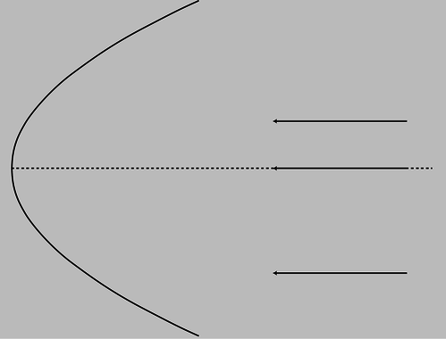
b / Problem 6.
6. The figure on the next page shows a curved (parabolic) mirror, with three parallel light rays coming toward it. One ray is approaching along the mirror's center line. (a) Trace the drawing accurately, and continue the light rays until they are about to undergo their second reflection. To get good enough accuracy, you'll need to photocopy the page (or download the book and print the page) and draw in the normal at each place where a ray is reflected. What do you notice? (b) Make up an example of a practical use for this device. (c) How could you use this mirror with a small lightbulb to produce a parallel beam of light rays going off to the right?
7. (answer check available at lightandmatter.com) A man is walking at 1.0 m/s directly towards a flat mirror. At what speed is his separation from his image decreasing?
8. If a mirror on a wall is only big enough for you to see yourself from your head down to your waist, can you see your entire body by backing up? Test this experimentally and come up with an explanation for your observations, including a ray diagram.
Note that when you do the experiment, it's easy to confuse yourself if the mirror is even a tiny bit off of vertical. One way to check yourself is to artificially lower the top of the mirror by putting a piece of tape or a post-it note where it blocks your view of the top of your head. You can then check whether you are able to see more of yourself both above and below by backing up.
9. In section 12.2 we've only done examples of mirrors with hollowed-out shapes (called concave mirrors). Now draw a ray diagram for a curved mirror that has a bulging outward shape (called a convex mirror). (a) How does the image's distance from the mirror compare with the actual object's distance from the mirror? From this comparison, determine whether the magnification is greater than or less than one. (b) Is the image real, or virtual? Could this mirror ever make the other type of image?
10. As discussed in question 9, there are two types of curved mirrors, concave and convex. Make a list of all the possible combinations of types of images (virtual or real) with types of mirrors (concave and convex). (Not all of the four combinations are physically possible.) Now for each one, use ray diagrams to determine whether increasing the distance of the object from the mirror leads to an increase or a decrease in the distance of the image from the mirror.
Draw BIG ray diagrams! Each diagram should use up about half a page of paper.
Some tips: To draw a ray diagram, you need two rays. For one of these, pick the ray that comes straight along the mirror's axis, since its reflection is easy to draw. After you draw the two rays and locate the image for the original object position, pick a new object position that results in the same type of image, and start a new ray diagram, in a different color of pen, right on top of the first one. For the two new rays, pick the ones that just happen to hit the mirror at the same two places; this makes it much easier to get the result right without depending on extreme accuracy in your ability to draw the reflected rays.
11. If the user of an astronomical telescope moves her head closer to or farther away from the image she is looking at, does the magnification change? Does the angular magnification change? Explain. (For simplicity, assume that no eyepiece is being used.)
12. In figure g/2 in on page 752, only the image of my forehead was located by drawing rays. Either photocopy the figure or download the book and print out the relevant page. On this copy of the figure, make a new set of rays coming from my chin, and locate its image. To make it easier to judge the angles accurately, draw rays from the chin that happen to hit the mirror at the same points where the two rays from the forehead were shown hitting it. By comparing the locations of the chin's image and the forehead's image, verify that the image is actually upside-down, as shown in the original figure.
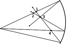
c / Problem 13.
13. The figure shows four points where rays cross. Of these, which are image points? Explain.
14. Here's a game my kids like to play. I sit next to a sunny window, and the sun reflects from the glass on my watch, making a disk of light on the wall or floor, which they pretend to chase as I move it around. Is the spot a disk because that's the shape of the sun, or because it's the shape of my watch? In other words, would a square watch make a square spot, or do we just have a circular image of the circular sun, which will be circular no matter what?
15. Apply the equation \(M=d_i/d_o\) to the case of a flat mirror.
16. (solution in the pdf version of the book) Use the method described in the text to derive the equation relating object distance to image distance for the case of a virtual image produced by a converging mirror.
17. Find the focal length of the mirror in problem 6 .(answer check available at lightandmatter.com)
![]()
d / Problem 18.
18. Rank the focal lengths of the mirrors in the figure, from shortest to longest. Explain.
19. (solution in the pdf version of the book) (a) A converging mirror with a focal length of 20 cm is used to create an image, using an object at a distance of 10 cm. Is the image real, or is it virtual? (b) How about \(f=20\) cm and \(d_o=30\) cm? (c) What if it was a diverging mirror with \(f=20\) cm and \(d_o=10\) cm? (d) A diverging mirror with \(f=20\) cm and \(d_o=30\) cm?
20. (a) Make up a numerical example of a virtual image formed by a converging mirror with a certain focal length, and determine the magnification. (You will need the result of problem 16.) Make sure to choose values of \(d_o\) and \(f\) that would actually produce a virtual image, not a real one. Now change the location of the object a little bit and redetermine the magnification, showing that it changes. At my local department store, the cosmetics department sells hand mirrors advertised as giving a magnification of 5 times. How would you interpret this?
(b) Suppose a Newtonian telescope is being used for astronomical observing. Assume for simplicity that no eyepiece is used, and assume a value for the focal length of the mirror that would be reasonable for an amateur instrument that is to fit in a closet. Is the angular magnification different for objects at different distances? For example, you could consider two planets, one of which is twice as far as the other.
21. (a) Find a case where the magnification of a curved mirror is infinite. Is the angular magnification infinite from any realistic viewing position? (b) Explain why an arbitrarily large magnification can't be achieved by having a sufficiently small value of \(d_o\).
22. A concave surface that reflects sound waves can act just like a converging mirror. Suppose that, standing near such a surface, you are able to find a point where you can place your head so that your own whispers are focused back on your head, so that they sound loud to you. Given your distance to the surface, what is the surface's focal length?
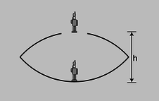
e / Problem 23.
23. The figure shows a device for constructing a realistic optical illusion. Two mirrors of equal focal length are put against each other with their silvered surfaces facing inward. A small object placed in the bottom of the cavity will have its image projected in the air above. The way it works is that the top mirror produces a virtual image, and the bottom mirror then creates a real image of the virtual image. (a) Show that if the image is to be positioned as shown, at the mouth of the cavity, then the focal length of the mirrors is related to the dimension \(h\) via the equation
\[\begin{equation*} \frac{1}{f} = \frac{1}{h}+\frac{1}{h+\left(\frac{1}{h}-\frac{1}{f}\right)^{-1}} . \end{equation*}\]
(b) Restate the equation in terms of a single variable \(x=h/f\), and show that there are two solutions for \(x\). Which solution is physically consistent with the assumptions of the calculation?
24. (a) A converging mirror is being used to create a virtual image. What is the range of possible magnifications? (b) Do the same for the other types of images that can be formed by curved mirrors (both converging and diverging).
25. A diverging mirror of focal length \(f\) is fixed, and faces down. An object is dropped from the surface of the mirror, and falls away from it with acceleration \(g\). The goal of the problem is to find the maximum velocity of the image.
(a) Describe the motion of the image verbally, and explain why we should expect there to be a maximum velocity.
(b) Use arguments based on units to determine the form of the solution, up to an unknown unitless multiplicative constant.
(c) Complete the solution by determining the unitless constant.
26. Diamond has an index of refraction of 2.42, and part of the reason diamonds sparkle is that this encourages a light ray to undergo many total internal reflections before it emerges. (a) Calculate the critical angle at which total internal reflection occurs in diamond. (answer check available at lightandmatter.com) (b) Explain the interpretation of your result: Is it measured from the normal, or from the surface? Is it a minimum, or a maximum? How would the critical angle have been different for a substance such as glass or plastic, with a lower index of refraction?
27. Suppose a converging lens is constructed of a type of plastic whose index of refraction is less than that of water. How will the lens's behavior be different if it is placed underwater?
28. There are two main types of telescopes, refracting (using a lens) and reflecting (using a mirror, as in figure i on p. 754). (Some telescopes use a mixture of the two types of elements: the light first encounters a large curved mirror, and then goes through an eyepiece that is a lens. To keep things simple, assume no eyepiece is used.) What implications would the color-dependence of focal length have for the relative merits of the two types of telescopes? Describe the case where an image is formed of a white star. You may find it helpful to draw a ray diagram.
29. Based on Snell's law, explain why rays of light passing through the edges of a converging lens are bent more than rays passing through parts closer to the center. It might seem like it should be the other way around, since the rays at the edge pass through less glass --- shouldn't they be affected less? In your answer:
- Include a ray diagram showing a huge, full-page, close-up view of the relevant part of the lens.
- Make use of the fact that the front and back surfaces aren't always parallel; a lens in which the front and back surfaces are always parallel doesn't focus light at all, so if your explanation doesn't make use of this fact, your argument must be incorrect.
- Make sure your argument still works even if the rays don't come in parallel to the axis.
30. When you take pictures with a camera, the distance between the lens and the film has to be adjusted, depending on the distance at which you want to focus. This is done by moving the lens. If you want to change your focus so that you can take a picture of something farther away, which way do you have to move the lens? Explain using ray diagrams. [Based on a problem by Eric Mazur.]
31. When swimming underwater, why is your vision made much clearer by wearing goggles with flat pieces of glass that trap air behind them? [Hint: You can simplify your reasoning by considering the special case where you are looking at an object far away, and along the optic axis of the eye.]
32. (answer check available at lightandmatter.com) An object is more than one focal length from a converging lens. (a) Draw a ray diagram. (b) Using reasoning like that developed in section 12.3, determine the positive and negative signs in the equation \(1/f=\pm1/d_i\pm1/d_o\). (c) The images of the rose in section 4.2 were made using a lens with a focal length of 23 cm. If the lens is placed 80 cm from the rose, locate the image.
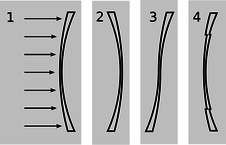
f / Problem 33.
33. The figure shows four lenses. Lens 1 has two spherical surfaces. Lens 2 is the same as lens 1 but turned around. Lens 3 is made by cutting through lens 1 and turning the bottom around. Lens 4 is made by cutting a central circle out of lens 1 and recessing it.
(a) A parallel beam of light enters lens 1 from the left, parallel to its axis. Reasoning based on Snell's law, will the beam emerging from the lens be bent inward, or outward, or will it remain parallel to the axis? Explain your reasoning. As part of your answer, make a huge drawing of one small part of the lens, and apply Snell's law at both interfaces. Recall that rays are bent more if they come to the interface at a larger angle with respect to the normal.
(b) What will happen with lenses 2, 3, and 4? Explain. Drawings are not necessary.
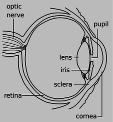
g / Problem 34.
34. The drawing shows the anatomy of the human eye, at twice life size. Find the radius of curvature of the outer surface of the cornea by measurements on the figure, and then derive the focal length of the air-cornea interface, where almost all the focusing of light occurs. You will need to use physical reasoning to modify the lensmaker's equation for the case where there is only a single refracting surface. Assume that the index of refraction of the cornea is essentially that of water.
35. (answer check available at lightandmatter.com) An object is less than one focal length from a converging lens. (a) Draw a ray diagram. (b) Using reasoning like that developed in section 12.3, determine the positive and negative signs in the equation \(1/f=\pm1/d_i\pm1/d_o\). (c) The images of the rose in section 4.2 were made using a lens with a focal length of 23 cm. If the lens is placed 10 cm from the rose, locate the image.
36. (answer check available at lightandmatter.com) Nearsighted people wear glasses whose lenses are diverging. (a) Draw a ray diagram. For simplicity pretend that there is no eye behind the glasses. (b) Using reasoning like that developed in section 12.3, determine the positive and negative signs in the equation \(1/f=\pm1/d_i\pm1/d_o\). (c) If the focal length of the lens is 50.0 cm, and the person is looking at an object at a distance of 80.0 cm, locate the image.
37. (a) Light is being reflected diffusely from an object 1.000 m underwater. The light that comes up to the surface is refracted at the water-air interface. If the refracted rays all appear to come from the same point, then there will be a virtual image of the object in the water, above the object's actual position, which will be visible to an observer above the water. Consider three rays, A, B and C, whose angles in the water with respect to the normal are \(\theta_i=0.000°\), \(1.000°\) and \(20.000°\) respectively. Find the depth of the point at which the refracted parts of A and B appear to have intersected, and do the same for A and C. Show that the intersections are at nearly the same depth, but not quite. [Check: The difference in depth should be about 4 cm.]
(b) Since all the refracted rays do not quite appear to have come from the same point, this is technically not a virtual image. In practical terms, what effect would this have on what you see?
(c) In the case where the angles are all small, use algebra and trig to show that the refracted rays do appear to come from the same point, and find an equation for the depth of the virtual image. Do not put in any numerical values for the angles or for the indices of refraction --- just keep them as symbols. You will need the approximation \(\sin\theta\approx \tan\theta\approx \theta\), which is valid for small angles measured in radians.
38. Prove that the principle of least time leads to Snell's law.
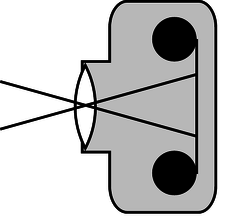
h / Problem 39.
39. (solution in the pdf version of the book) Two standard focal lengths for camera lenses are 50 mm (standard) and 28 mm (wide-angle). To see how the focal lengths relate to the angular size of the field of view, it is helpful to visualize things as represented in the figure. Instead of showing many rays coming from the same point on the same object, as we normally do, the figure shows two rays from two different objects. Although the lens will intercept infinitely many rays from each of these points, we have shown only the ones that pass through the center of the lens, so that they suffer no angular deflection. (Any angular deflection at the front surface of the lens is canceled by an opposite deflection at the back, since the front and back surfaces are parallel at the lens's center.) What is special about these two rays is that they are aimed at the edges of one 35-mm-wide frame of film; that is, they show the limits of the field of view. Throughout this problem, we assume that \(d_o\) is much greater than \(d_i\). (a) Compute the angular width of the camera's field of view when these two lenses are used. (b) Use small-angle approximations to find a simplified equation for the angular width of the field of view, \(\theta \), in terms of the focal length, \(f\), and the width of the film, \(w\). Your equation should not have any trig functions in it. Compare the results of this approximation with your answers from part a. (c) Suppose that we are holding constant the aperture (amount of surface area of the lens being used to collect light). When switching from a 50-mm lens to a 28-mm lens, how many times longer or shorter must the exposure be in order to make a properly developed picture, i.e., one that is not under- or overexposed? [Based on a problem by Arnold Arons.]
40. A nearsighted person is one whose eyes focus light too strongly, and who is therefore unable to relax the lens inside her eye sufficiently to form an image on her retina of an object that is too far away.
(a) Draw a ray diagram showing what happens when the person tries, with uncorrected vision, to focus at infinity.
(b) What type of lenses do her glasses have? Explain.
(c) Draw a ray diagram showing what happens when she wears glasses. Locate both the image formed by the glasses and the final image.
(d) Suppose she sometimes uses contact lenses instead of her glasses. Does the focal length of her contacts have to be less than, equal to, or greater than that of her glasses? Explain.
41. Fred's eyes are able to focus on things as close as 5.0 cm. Fred holds a magnifying glass with a focal length of 3.0 cm at a height of 2.0 cm above a flatworm. (a) Locate the image, and find the magnification. (b) Without the magnifying glass, from what distance would Fred want to view the flatworm to see its details as well as possible? With the magnifying glass? (c) Compute the angular magnification.
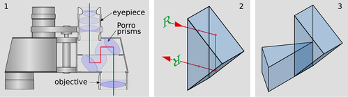
i / Problem 42.
42. Panel 1 of the figure shows the optics inside a pair of binoculars. They are essentially a pair of telescopes, one for each eye. But to make them more compact, and allow the eyepieces to be the right distance apart for a human face, they incorporate a set of eight prisms, which fold the light path. In addition, the prisms make the image upright. Panel 2 shows one of these prisms, known as a Porro prism. The light enters along a normal, undergoes two total internal reflections at angles of 45 degrees with respect to the back surfaces, and exits along a normal. The image of the letter R has been flipped across the horizontal. Panel 3 shows a pair of these prisms glued together. The image will be flipped across both the horizontal and the vertical, which makes it oriented the right way for the user of the binoculars.
(a) Find the minimum possible index of refraction for the glass used in the prisms.
(b) For a material of this minimal index of refraction, find the fraction of the incoming light that will be lost to reflection in the four Porro prisms on a each side of a pair of binoculars. (See section 6.2.) In real, high-quality binoculars, the optical surfaces of the prisms have antireflective coatings, but carry out your calculation for the case where there is no such coating.
(c) Discuss the reasons why a designer of binoculars might or might not want to use a material with exactly the index of refraction found in part a.
43. It would be annoying if your eyeglasses produced a magnified or reduced image. Prove that when the eye is very close to a lens, and the lens produces a virtual image, the angular magnification is always approximately equal to 1 (regardless of whether the lens is diverging or converging).
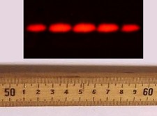
44. The figure shows a diffraction pattern made by a double slit, along with an image of a meter stick to show the scale. Sketch the diffraction pattern from the figure on your paper. Now consider the four variables in the equation \(\lambda /d=\sin \theta /m\). Which of these are the same for all five fringes, and which are different for each fringe? Which variable would you naturally use in order to label which fringe was which? Label the fringes on your sketch using the values of that variable.
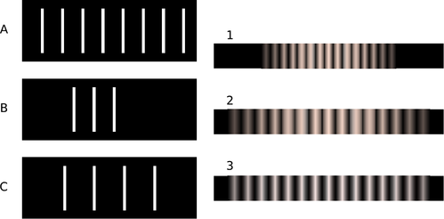
45. Match gratings A-C with the diffraction patterns 1-3 that they produce. Explain.
46. The figure below shows two diffraction patterns. The top one was made with yellow light, and the bottom one with red. Could the slits used to make the two patterns have been the same?

j / Problems 44 and 47.
47. The figure on p. 805 shows a diffraction pattern made by a double slit, along with an image of a meter stick to show the scale. The slits were 146 cm away from the screen on which the diffraction pattern was projected. The spacing of the slits was 0.050 mm. What was the wavelength of the light?(answer check available at lightandmatter.com)
48. Why would blue or violet light be the best for microscopy?
49. The figure below shows two diffraction patterns, both made with the same wavelength of red light. (a) What type of slits made the patterns? Is it a single slit, double slits, or something else? Explain. (b) Compare the dimensions of the slits used to make the top and bottom pattern. Give a numerical ratio, and state which way the ratio is, i.e., which slit pattern was the larger one. Explain.

50. When white light passes through a diffraction grating, what is the smallest value of \(m\) for which the visible spectrum of order \(m\) overlaps the next one, of order \(m+1?\) (The visible spectrum runs from about 400 nm to about 700 nm.)
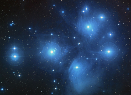
k / Problem 51. This image of the Pleiades star cluster shows haloes around the stars due to the wave nature of light.
51. For star images such as the ones in figure y, estimate the angular width of the diffraction spot due to diffraction at the mouth of the telescope. Assume a telescope with a diameter of 10 meters (the largest currently in existence), and light with a wavelength in the middle of the visible range. Compare with the actual angular size of a star of diameter \(10^9\) m seen from a distance of \(10^{17}\) m. What does this tell you?
52. The figure below shows three diffraction patterns. All were made under identical conditions, except that a different set of double slits was used for each one. The slits used to make the top pattern had a center-to-center separation \(d=0.50\) mm, and each slit was \(w=0.04\) mm wide. (a) Determine \(d\) and \(w\) for the slits used to make the pattern in the middle. (b) Do the same for the slits used to make the bottom pattern.

53. (answer check available at lightandmatter.com) The beam of a laser passes through a diffraction grating, fans out, and illuminates a wall that is perpendicular to the original beam, lying at a distance of 2.0 m from the grating. The beam is produced by a helium-neon laser, and has a wavelength of 694.3 nm. The grating has 2000 lines per centimeter. (a) What is the distance on the wall between the central maximum and the maxima immediately to its right and left? (b) How much does your answer change when you use the small-angle approximations \(\theta\approx\sin\theta\approx\tan\theta\)?
54. Ultrasound, i.e., sound waves with frequencies too high to be audible, can be used for imaging fetuses in the womb or for breaking up kidney stones so that they can be eliminated by the body. Consider the latter application. Lenses can be built to focus sound waves, but because the wavelength of the sound is not all that small compared to the diameter of the lens, the sound will not be concentrated exactly at the geometrical focal point. Instead, a diffraction pattern will be created with an intense central spot surrounded by fainter rings. About 85% of the power is concentrated within the central spot. The angle of the first minimum (surrounding the central spot) is given by \(\sin \theta =\lambda/b\), where \(b\) is the diameter of the lens. This is similar to the corresponding equation for a single slit, but with a factor of 1.22 in front which arises from the circular shape of the aperture. Let the distance from the lens to the patient's kidney stone be \(L=20\) cm. You will want \(f>20\) kHz, so that the sound is inaudible. Find values of \(b\) and \(f\) that would result in a usable design, where the central spot is small enough to lie within a kidney stone 1 cm in diameter.
55. Under what circumstances could one get a mathematically undefined result by solving the double-slit diffraction equation for \(\theta \)? Give a physical interpretation of what would actually be observed.
56. When ultrasound is used for medical imaging, the frequency may be as high as 5-20 MHz. Another medical application of ultrasound is for therapeutic heating of tissues inside the body; here, the frequency is typically 1-3 MHz. What fundamental physical reasons could you suggest for the use of higher frequencies for imaging?
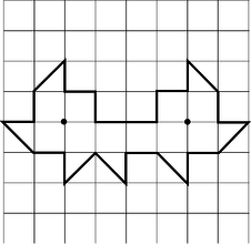
l / Problem 57.
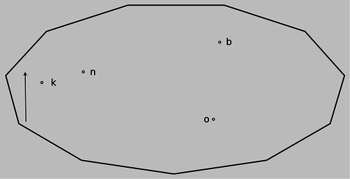
57. Suppose we have a polygonal room whose walls are mirrors, and there a pointlike light source in the room. In most such examples, every point in the room ends up being illuminated by the light source after some finite number of reflections. A difficult mathematical question, first posed in the middle of the last century, is whether it is ever possible to have an example in which the whole room is not illuminated. (Rays are assumed to be absorbed if they strike exactly at a vertex of the polygon, or if they pass exactly through the plane of a mirror.)
The problem was finally solved in 1995 by G.W. Tokarsky, who found an example of a room that was not illuminable from a certain point. Figure 57 shows a slightly simpler example found two years later by D. Castro. If a light source is placed at either of the locations shown with dots, the other dot remains unilluminated, although every other point is lit up. It is not straightforward to prove rigorously that Castro's solution has this property. However, the plausibility of the solution can be demonstrated as follows.
Suppose the light source is placed at the right-hand dot. Locate all the images formed by single reflections. Note that they form a regular pattern. Convince yourself that none of these images illuminates the left-hand dot. Because of the regular pattern, it becomes plausible that even if we form images of images, images of images of images, etc., none of them will ever illuminate the other dot.
There are various other versions of the problem, some of which remain unsolved. The book by Klee and Wagon gives a good introduction to the topic, although it predates Tokarsky and Castro's work.
References:
G.W. Tokarsky, “Polygonal Rooms Not Illuminable from Every Point.” Amer. Math. Monthly 102, 867-879, 1995.
D. Castro, “Corrections.” Quantum 7, 42, Jan. 1997.
V. Klee and S. Wagon, Old and New Unsolved Problems in Plane Geometry and Number Theory. Mathematical Association of America, 1991.
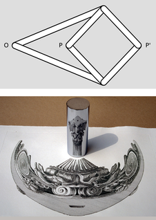
m / Problem 58.
58. A mechanical linkage is a device that changes one type of motion into another. The most familiar example occurs in a gasoline car's engine, where a connecting rod changes the linear motion of the piston into circular motion of the crankshaft. The top panel of the figure shows a mechanical linkage invented by Peaucellier in 1864, and independently by Lipkin around the same time. It consists of six rods joined by hinges, the four short ones forming a rhombus. Point O is fixed in space, but the apparatus is free to rotate about O. Motion at P is transformed into a different motion at \(\text{P}'\) (or vice versa).
Geometrically, the linkage is a mechanical implementation of the ancient problem of inversion in a circle. Considering the case in which the rhombus is folded flat, let the \(k\) be the distance from O to the point where P and \(\text{P}'\) coincide. Form the circle of radius \(k\) with its center at O. As P and \(\text{P}'\) move in and out, points on the inside of the circle are always mapped to points on its outside, such that \(rr'=k^2\). That is, the linkage is a type of analog computer that exactly solves the problem of finding the inverse of a number \(r\). Inversion in a circle has many remarkable geometrical properties, discussed in H.S.M. Coxeter, Introduction to Geometry, Wiley, 1961. If a pen is inserted through a hole at P, and \(\text{P}'\) is traced over a geometrical figure, the Peaucellier linkage can be used to draw a kind of image of the figure.
A related problem is the construction of pictures, like the one in the bottom panel of the figure, called anamorphs. The drawing of the column on the paper is highly distorted, but when the reflecting cylinder is placed in the correct spot on top of the page, an undistorted image is produced inside the cylinder. (Wide-format movie technologies such as Cinemascope are based on similar principles.)
Show that the Peaucellier linkage does not convert correctly between an image and its anamorph, and design a modified version of the linkage that does. Some knowledge of analytic geometry will be helpful.
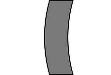
n / Problem 59.
59. The figure shows a lens with surfaces that are curved, but whose thickness is constant along any horizontal line. Use the lensmaker's equation to prove that this “lens” is not really a lens at all.(solution in the pdf version of the book)
60. Under ordinary conditions, gases have indices of refraction only a little greater than that of vacuum, i.e., \(n=1+\epsilon\), where \(\epsilon\) is some small number. Suppose that a ray crosses a boundary between a region of vacuum and a region in which the index of refraction is \(1+\epsilon\). Find the maximum angle by which such a ray can ever be deflected, in the limit of small \(\epsilon\). \hwhint{hwhint:very-weak-refraction}
61. A converging mirror has focal length \(f\). An object is located at a distance \((1+\epsilon)f\) from the mirror, where \(\epsilon\) is small. Find the distance of the image from the mirror, simplifying your result as much as possible by using the assumption that \(\epsilon\) is small. \hwans{hwans:close-to-focal-length}
Benjamin Crowell (Fullerton College). Conceptual Physics is copyrighted with a CC-BY-SA license.