13.2: Images by Reflection
- Page ID
- 982
\( \newcommand{\vecs}[1]{\overset { \scriptstyle \rightharpoonup} {\mathbf{#1}} } \)
\( \newcommand{\vecd}[1]{\overset{-\!-\!\rightharpoonup}{\vphantom{a}\smash {#1}}} \)
\( \newcommand{\dsum}{\displaystyle\sum\limits} \)
\( \newcommand{\dint}{\displaystyle\int\limits} \)
\( \newcommand{\dlim}{\displaystyle\lim\limits} \)
\( \newcommand{\id}{\mathrm{id}}\) \( \newcommand{\Span}{\mathrm{span}}\)
( \newcommand{\kernel}{\mathrm{null}\,}\) \( \newcommand{\range}{\mathrm{range}\,}\)
\( \newcommand{\RealPart}{\mathrm{Re}}\) \( \newcommand{\ImaginaryPart}{\mathrm{Im}}\)
\( \newcommand{\Argument}{\mathrm{Arg}}\) \( \newcommand{\norm}[1]{\| #1 \|}\)
\( \newcommand{\inner}[2]{\langle #1, #2 \rangle}\)
\( \newcommand{\Span}{\mathrm{span}}\)
\( \newcommand{\id}{\mathrm{id}}\)
\( \newcommand{\Span}{\mathrm{span}}\)
\( \newcommand{\kernel}{\mathrm{null}\,}\)
\( \newcommand{\range}{\mathrm{range}\,}\)
\( \newcommand{\RealPart}{\mathrm{Re}}\)
\( \newcommand{\ImaginaryPart}{\mathrm{Im}}\)
\( \newcommand{\Argument}{\mathrm{Arg}}\)
\( \newcommand{\norm}[1]{\| #1 \|}\)
\( \newcommand{\inner}[2]{\langle #1, #2 \rangle}\)
\( \newcommand{\Span}{\mathrm{span}}\) \( \newcommand{\AA}{\unicode[.8,0]{x212B}}\)
\( \newcommand{\vectorA}[1]{\vec{#1}} % arrow\)
\( \newcommand{\vectorAt}[1]{\vec{\text{#1}}} % arrow\)
\( \newcommand{\vectorB}[1]{\overset { \scriptstyle \rightharpoonup} {\mathbf{#1}} } \)
\( \newcommand{\vectorC}[1]{\textbf{#1}} \)
\( \newcommand{\vectorD}[1]{\overrightarrow{#1}} \)
\( \newcommand{\vectorDt}[1]{\overrightarrow{\text{#1}}} \)
\( \newcommand{\vectE}[1]{\overset{-\!-\!\rightharpoonup}{\vphantom{a}\smash{\mathbf {#1}}}} \)
\( \newcommand{\vecs}[1]{\overset { \scriptstyle \rightharpoonup} {\mathbf{#1}} } \)
\(\newcommand{\longvect}{\overrightarrow}\)
\( \newcommand{\vecd}[1]{\overset{-\!-\!\rightharpoonup}{\vphantom{a}\smash {#1}}} \)
\(\newcommand{\avec}{\mathbf a}\) \(\newcommand{\bvec}{\mathbf b}\) \(\newcommand{\cvec}{\mathbf c}\) \(\newcommand{\dvec}{\mathbf d}\) \(\newcommand{\dtil}{\widetilde{\mathbf d}}\) \(\newcommand{\evec}{\mathbf e}\) \(\newcommand{\fvec}{\mathbf f}\) \(\newcommand{\nvec}{\mathbf n}\) \(\newcommand{\pvec}{\mathbf p}\) \(\newcommand{\qvec}{\mathbf q}\) \(\newcommand{\svec}{\mathbf s}\) \(\newcommand{\tvec}{\mathbf t}\) \(\newcommand{\uvec}{\mathbf u}\) \(\newcommand{\vvec}{\mathbf v}\) \(\newcommand{\wvec}{\mathbf w}\) \(\newcommand{\xvec}{\mathbf x}\) \(\newcommand{\yvec}{\mathbf y}\) \(\newcommand{\zvec}{\mathbf z}\) \(\newcommand{\rvec}{\mathbf r}\) \(\newcommand{\mvec}{\mathbf m}\) \(\newcommand{\zerovec}{\mathbf 0}\) \(\newcommand{\onevec}{\mathbf 1}\) \(\newcommand{\real}{\mathbb R}\) \(\newcommand{\twovec}[2]{\left[\begin{array}{r}#1 \\ #2 \end{array}\right]}\) \(\newcommand{\ctwovec}[2]{\left[\begin{array}{c}#1 \\ #2 \end{array}\right]}\) \(\newcommand{\threevec}[3]{\left[\begin{array}{r}#1 \\ #2 \\ #3 \end{array}\right]}\) \(\newcommand{\cthreevec}[3]{\left[\begin{array}{c}#1 \\ #2 \\ #3 \end{array}\right]}\) \(\newcommand{\fourvec}[4]{\left[\begin{array}{r}#1 \\ #2 \\ #3 \\ #4 \end{array}\right]}\) \(\newcommand{\cfourvec}[4]{\left[\begin{array}{c}#1 \\ #2 \\ #3 \\ #4 \end{array}\right]}\) \(\newcommand{\fivevec}[5]{\left[\begin{array}{r}#1 \\ #2 \\ #3 \\ #4 \\ #5 \\ \end{array}\right]}\) \(\newcommand{\cfivevec}[5]{\left[\begin{array}{c}#1 \\ #2 \\ #3 \\ #4 \\ #5 \\ \end{array}\right]}\) \(\newcommand{\mattwo}[4]{\left[\begin{array}{rr}#1 \amp #2 \\ #3 \amp #4 \\ \end{array}\right]}\) \(\newcommand{\laspan}[1]{\text{Span}\{#1\}}\) \(\newcommand{\bcal}{\cal B}\) \(\newcommand{\ccal}{\cal C}\) \(\newcommand{\scal}{\cal S}\) \(\newcommand{\wcal}{\cal W}\) \(\newcommand{\ecal}{\cal E}\) \(\newcommand{\coords}[2]{\left\{#1\right\}_{#2}}\) \(\newcommand{\gray}[1]{\color{gray}{#1}}\) \(\newcommand{\lgray}[1]{\color{lightgray}{#1}}\) \(\newcommand{\rank}{\operatorname{rank}}\) \(\newcommand{\row}{\text{Row}}\) \(\newcommand{\col}{\text{Col}}\) \(\renewcommand{\row}{\text{Row}}\) \(\newcommand{\nul}{\text{Nul}}\) \(\newcommand{\var}{\text{Var}}\) \(\newcommand{\corr}{\text{corr}}\) \(\newcommand{\len}[1]{\left|#1\right|}\) \(\newcommand{\bbar}{\overline{\bvec}}\) \(\newcommand{\bhat}{\widehat{\bvec}}\) \(\newcommand{\bperp}{\bvec^\perp}\) \(\newcommand{\xhat}{\widehat{\xvec}}\) \(\newcommand{\vhat}{\widehat{\vvec}}\) \(\newcommand{\uhat}{\widehat{\uvec}}\) \(\newcommand{\what}{\widehat{\wvec}}\) \(\newcommand{\Sighat}{\widehat{\Sigma}}\) \(\newcommand{\lt}{<}\) \(\newcommand{\gt}{>}\) \(\newcommand{\amp}{&}\) \(\definecolor{fillinmathshade}{gray}{0.9}\)Infants are always fascinated by the antics of the Baby in the Mirror. Now if you want to know something about mirror images that most people don't understand, try this. First bring this page closer and closer to your eyes, until you can no longer focus on it without straining. Then go in the bathroom and see how close you can get your face to the surface of the mirror before you can no longer easily focus on the image of your own eyes. You will find that the shortest comfortable eye-mirror distance is much less than the shortest comfortable eye-paper distance. This demonstrates that the image of your face in the mirror acts as if it had depth and existed in the space behind the mirror. If the image was like a flat picture in a book, then you wouldn't be able to focus on it from such a short distance.
In this chapter we will study the images formed by flat and curved mirrors on a qualitative, conceptual basis. Although this type of image is not as commonly encountered in everyday life as images formed by lenses, images formed by reflection are simpler to understand, so we discuss them first. In section 12.3 we will turn to a more mathematical treatment of images made by reflection. Surprisingly, the same equations can also be applied to lenses, which are the topic of section 12.4.
12.2.1 A virtual image
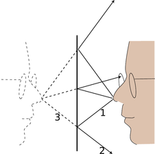
a / An image formed by a mirror.
We can understand a mirror image using a ray diagram. Figure a shows several light rays, 1, that originated by diffuse reflection at the person's nose. They bounce off the mirror, producing new rays, 2. To anyone whose eye is in the right position to get one of these rays, they appear to have come from a behind the mirror, 3, where they would have originated from a single point. This point is where the tip of the image-person's nose appears to be. A similar analysis applies to every other point on the person's face, so it looks as though there was an entire face behind the mirror. The customary way of describing the situation requires some explanation:
- Customary description in physics: There is an image of the face behind the mirror.
- Translation: The pattern of rays coming from the mirror is exactly the same as it would be if there were a face behind the mirror. Nothing is really behind the mirror.
This is referred to as a virtual image, because the rays do not actually cross at the point behind the mirror. They only appear to have originated there.
self-check:
Imagine that the person in figure a moves his face down quite a bit --- a couple of feet in real life, or a few inches on this scale drawing. The mirror stays where it is. Draw a new ray diagram. Will there still be an image? If so, where is it visible from?
(answer in the back of the PDF version of the book)
The geometry of specular reflection tells us that rays 1 and 2 are at equal angles to the normal (the imaginary perpendicular line piercing the mirror at the point of reflection). This means that ray 2's imaginary continuation, 3, forms the same angle with the mirror as ray 1. Since each ray of type 3 forms the same angles with the mirror as its partner of type 1, we see that the distance of the image from the mirror is the same as that of the actual face from the mirror, and it lies directly across from it. The image therefore appears to be the same size as the actual face.
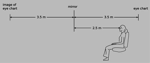
b / Example 2.
| Example 2: An eye exam |
|---|
|
Figure b shows a typical setup in an optometrist's examination room. The patient's vision is supposed to be tested at a distance of 6 meters (20 feet in the U.S.), but this distance is larger than the amount of space available in the room. Therefore a mirror is used to create an image of the eye chart behind the wall. |
| Example 3: The Praxinoscope |
|---|
|
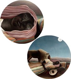
c / The praxinoscope. Figure c shows an old-fashioned device called a praxinoscope, which displays an animated picture when spun. The removable strip of paper with the pictures printed on it has twice the radius of the inner circle made of flat mirrors, so each picture's virtual image is at the center. As the wheel spins, each picture's image is replaced by the next. |
Discussion Question
◊ The figure shows an object that is off to one side of a mirror. Draw a ray diagram. Is an image formed? If so, where is it, and from which directions would it be visible?
12.2.2 Curved mirrors
An image in a flat mirror is a pretechnological example: even animals can look at their reflections in a calm pond. We now pass to our first nontrivial example of the manipulation of an image by technology: an image in a curved mirror. Before we dive in, let's consider why this is an important example. If it was just a question of memorizing a bunch of facts about curved mirrors, then you would rightly rebel against an effort to spoil the beauty of your liberally educated brain by force-feeding you technological trivia. The reason this is an important example is not that curved mirrors are so important in and of themselves, but that the results we derive for curved bowl-shaped mirrors turn out to be true for a large class of other optical devices, including mirrors that bulge outward rather than inward, and lenses as well. A microscope or a telescope is simply a combination of lenses or mirrors or both. What you're really learning about here is the basic building block of all optical devices from movie projectors to octopus eyes.
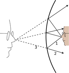
d / An image formed by a curved mirror.
Because the mirror in figure d is curved, it bends the rays back closer together than a flat mirror would: we describe it as converging. Note that the term refers to what it does to the light rays, not to the physical shape of the mirror's surface . (The surface itself would be described as concave. The term is not all that hard to remember, because the hollowed-out interior of the mirror is like a cave.) It is surprising but true that all the rays like 3 really do converge on a point, forming a good image. We will not prove this fact, but it is true for any mirror whose curvature is gentle enough and that is symmetric with respect to rotation about the perpendicular line passing through its center (not asymmetric like a potato chip). The old-fashioned method of making mirrors and lenses is by grinding them in grit by hand, and this automatically tends to produce an almost perfect spherical surface.
Bending a ray like 2 inward implies bending its imaginary continuation 3 outward, in the same way that raising one end of a seesaw causes the other end to go down. The image therefore forms deeper behind the mirror. This doesn't just show that there is extra distance between the image-nose and the mirror; it also implies that the image itself is bigger from front to back. It has been magnified in the front-to-back direction.
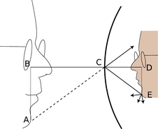
e / The image is magnified by the same factor in depth and in its other dimensions.
It is easy to prove that the same magnification also applies to the image's other dimensions. Consider a point like E in figure e. The trick is that out of all the rays diffusely reflected by E, we pick the one that happens to head for the mirror's center, C. The equal-angle property of specular reflection plus a little straightforward geometry easily leads us to the conclusion that triangles ABC and CDE are the same shape, with ABC being simply a scaled-up version of CDE. The magnification of depth equals the ratio BC/CD, and the up-down magnification is AB/DE. A repetition of the same proof shows that the magnification in the third dimension (out of the page) is also the same. This means that the image-head is simply a larger version of the real one, without any distortion. The scaling factor is called the magnification, \(M\). The image in the figure is magnified by a factor \(M=1.9\).
f / Increased magnification always comes at the expense of decreased field of view.
Note that we did not explicitly specify whether the mirror was a sphere, a paraboloid, or some other shape. However, we assumed that a focused image would be formed, which would not necessarily be true, for instance, for a mirror that was asymmetric or very deeply curved.
12.2.3 A real image
If we start by placing an object very close to the mirror, g/1, and then move it farther and farther away, the image at first behaves as we would expect from our everyday experience with flat mirrors, receding deeper and deeper behind the mirror. At a certain point, however, a dramatic change occurs. When the object is more than a certain distance from the mirror, g/2, the image appears upside-down and in front of the mirror.
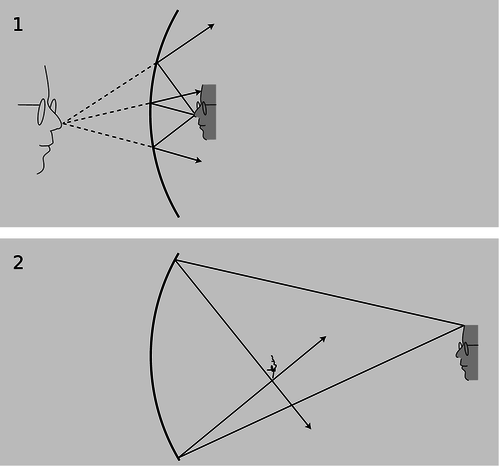
g / 1. A virtual image. 2. A real image. As you'll verify in homework problem 12, the image is upside-down
Here's what's happened. The mirror bends light rays inward, but when the object is very close to it, as in g/1, the rays coming from a given point on the object are too strongly diverging (spreading) for the mirror to bring them back together. On reflection, the rays are still diverging, just not as strongly diverging. But when the object is sufficiently far away, g/2, the mirror is only intercepting the rays that came out in a narrow cone, and it is able to bend these enough so that they will reconverge.
Note that the rays shown in the figure, which both originated at the same point on the object, reunite when they cross. The point where they cross is the image of the point on the original object. This type of image is called a real image, in contradistinction to the virtual images we've studied before.
Definition: A real image is one where rays actually cross. A virtual image is a point from which rays only appear to have come.
The use of the word “real” is perhaps unfortunate. It sounds as though we are saying the image was an actual material object, which of course it is not.
The distinction between a real image and a virtual image is an important one, because a real image can be projected onto a screen or photographic film. If a piece of paper is inserted in figure g/2 at the location of the image, the image will be visible on the paper (provided the object is bright and the room is dark). Your eye uses a lens to make a real image on the retina.
self-check:
Sketch another copy of the face in figure g/1, even farther from the mirror, and draw a ray diagram. What has happened to the location of the image?
(answer in the back of the PDF version of the book)
12.2.4 Images of images
If you are wearing glasses right now, then the light rays from the page are being manipulated first by your glasses and then by the lens of your eye. You might think that it would be extremely difficult to analyze this, but in fact it is quite easy. In any series of optical elements (mirrors or lenses or both), each element works on the rays furnished by the previous element in exactly the same manner as if the image formed by the previous element was an actual object.
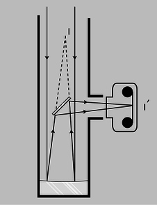
h / A Newtonian telescope being used with a camera.
Figure h shows an example involving only mirrors. The Newtonian telescope, invented by Isaac Newton, consists of a large curved mirror, plus a second, flat mirror that brings the light out of the tube. (In very large telescopes, there may be enough room to put a camera or even a person inside the tube, in which case the second mirror is not needed.) The tube of the telescope is not vital; it is mainly a structural element, although it can also be helpful for blocking out stray light. The lens has been removed from the front of the camera body, and is not needed for this setup. Note that the two sample rays have been drawn parallel, because an astronomical telescope is used for viewing objects that are extremely far away. These two “parallel” lines actually meet at a certain point, say a crater on the moon, so they can't actually be perfectly parallel, but they are parallel for all practical purposes since we would have to follow them upward for a quarter of a million miles to get to the point where they intersect.
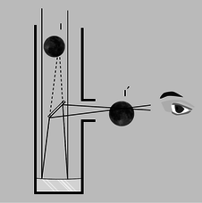
i / A Newtonian telescope being used for visual rather than photographic observing. In real life, an eyepiece lens is normally used for additional magnification, but this simpler setup will also work.
The large curved mirror by itself would form an image \(\text{I}\), but the small flat mirror creates an image of the image, \(\text{I}'\). The relationship between \(\text{I}\) and \(\text{I}'\) is exactly the same as it would be if \(\text{I}\) was an actual object rather than an image: \(\text{I}\) and \(\text{I}'\) are at equal distances from the plane of the mirror, and the line between them is perpendicular to the plane of the mirror.
One surprising wrinkle is that whereas a flat mirror used by itself forms a virtual image of an object that is real, here the mirror is forming a real image of virtual image \(\text{I}\). This shows how pointless it would be to try to memorize lists of facts about what kinds of images are formed by various optical elements under various circumstances. You are better off simply drawing a ray diagram.

j / The angular size of the flower depends on its distance from the eye.
Although the main point here was to give an example of an image of an image, figure i also shows an interesting case where we need to make the distinction between magnification and angular magnification. \(\text{I}\)f you are looking at the moon through this telescope, then the images \(\text{I}\) and \(\text{I}'\) are much smaller than the actual moon. Otherwise, for example, image \(\text{I}\) would not fit inside the telescope! However, these images are very close to your eye compared to the actual moon. The small size of the image has been more than compensated for by the shorter distance. The important thing here is the amount of angle within your field of view that the image covers, and it is this angle that has been increased. The factor by which it is increased is called the angular magnification, \(M_a\).
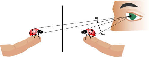
k / The person uses a mirror to get a view of both sides of the ladybug. Although the flat mirror has \(M=1\), it doesn't give an angular magnification of 1. The image is farther from the eye than the object, so the angular magnification \(M_a=\alpha_i/\alpha_o\) is less than one.
Discussion Questions
◊ Locate the images of you that will be formed if you stand between two parallel mirrors.

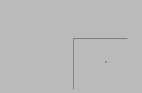
◊ Locate the images formed by two perpendicular mirrors, as in the figure. What happens if the mirrors are not perfectly perpendicular?
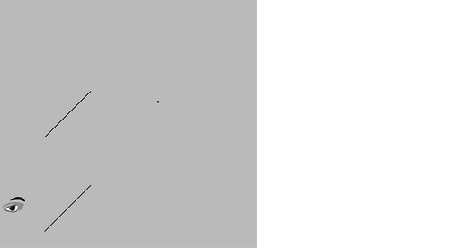
◊ Locate the images formed by the periscope.
Contributor
Benjamin Crowell (Fullerton College). Conceptual Physics is copyrighted with a CC-BY-SA license.


