7.2: Bounded Waves
- Page ID
- 957
\( \newcommand{\vecs}[1]{\overset { \scriptstyle \rightharpoonup} {\mathbf{#1}} } \)
\( \newcommand{\vecd}[1]{\overset{-\!-\!\rightharpoonup}{\vphantom{a}\smash {#1}}} \)
\( \newcommand{\dsum}{\displaystyle\sum\limits} \)
\( \newcommand{\dint}{\displaystyle\int\limits} \)
\( \newcommand{\dlim}{\displaystyle\lim\limits} \)
\( \newcommand{\id}{\mathrm{id}}\) \( \newcommand{\Span}{\mathrm{span}}\)
( \newcommand{\kernel}{\mathrm{null}\,}\) \( \newcommand{\range}{\mathrm{range}\,}\)
\( \newcommand{\RealPart}{\mathrm{Re}}\) \( \newcommand{\ImaginaryPart}{\mathrm{Im}}\)
\( \newcommand{\Argument}{\mathrm{Arg}}\) \( \newcommand{\norm}[1]{\| #1 \|}\)
\( \newcommand{\inner}[2]{\langle #1, #2 \rangle}\)
\( \newcommand{\Span}{\mathrm{span}}\)
\( \newcommand{\id}{\mathrm{id}}\)
\( \newcommand{\Span}{\mathrm{span}}\)
\( \newcommand{\kernel}{\mathrm{null}\,}\)
\( \newcommand{\range}{\mathrm{range}\,}\)
\( \newcommand{\RealPart}{\mathrm{Re}}\)
\( \newcommand{\ImaginaryPart}{\mathrm{Im}}\)
\( \newcommand{\Argument}{\mathrm{Arg}}\)
\( \newcommand{\norm}[1]{\| #1 \|}\)
\( \newcommand{\inner}[2]{\langle #1, #2 \rangle}\)
\( \newcommand{\Span}{\mathrm{span}}\) \( \newcommand{\AA}{\unicode[.8,0]{x212B}}\)
\( \newcommand{\vectorA}[1]{\vec{#1}} % arrow\)
\( \newcommand{\vectorAt}[1]{\vec{\text{#1}}} % arrow\)
\( \newcommand{\vectorB}[1]{\overset { \scriptstyle \rightharpoonup} {\mathbf{#1}} } \)
\( \newcommand{\vectorC}[1]{\textbf{#1}} \)
\( \newcommand{\vectorD}[1]{\overrightarrow{#1}} \)
\( \newcommand{\vectorDt}[1]{\overrightarrow{\text{#1}}} \)
\( \newcommand{\vectE}[1]{\overset{-\!-\!\rightharpoonup}{\vphantom{a}\smash{\mathbf {#1}}}} \)
\( \newcommand{\vecs}[1]{\overset { \scriptstyle \rightharpoonup} {\mathbf{#1}} } \)
\( \newcommand{\vecd}[1]{\overset{-\!-\!\rightharpoonup}{\vphantom{a}\smash {#1}}} \)
\(\newcommand{\avec}{\mathbf a}\) \(\newcommand{\bvec}{\mathbf b}\) \(\newcommand{\cvec}{\mathbf c}\) \(\newcommand{\dvec}{\mathbf d}\) \(\newcommand{\dtil}{\widetilde{\mathbf d}}\) \(\newcommand{\evec}{\mathbf e}\) \(\newcommand{\fvec}{\mathbf f}\) \(\newcommand{\nvec}{\mathbf n}\) \(\newcommand{\pvec}{\mathbf p}\) \(\newcommand{\qvec}{\mathbf q}\) \(\newcommand{\svec}{\mathbf s}\) \(\newcommand{\tvec}{\mathbf t}\) \(\newcommand{\uvec}{\mathbf u}\) \(\newcommand{\vvec}{\mathbf v}\) \(\newcommand{\wvec}{\mathbf w}\) \(\newcommand{\xvec}{\mathbf x}\) \(\newcommand{\yvec}{\mathbf y}\) \(\newcommand{\zvec}{\mathbf z}\) \(\newcommand{\rvec}{\mathbf r}\) \(\newcommand{\mvec}{\mathbf m}\) \(\newcommand{\zerovec}{\mathbf 0}\) \(\newcommand{\onevec}{\mathbf 1}\) \(\newcommand{\real}{\mathbb R}\) \(\newcommand{\twovec}[2]{\left[\begin{array}{r}#1 \\ #2 \end{array}\right]}\) \(\newcommand{\ctwovec}[2]{\left[\begin{array}{c}#1 \\ #2 \end{array}\right]}\) \(\newcommand{\threevec}[3]{\left[\begin{array}{r}#1 \\ #2 \\ #3 \end{array}\right]}\) \(\newcommand{\cthreevec}[3]{\left[\begin{array}{c}#1 \\ #2 \\ #3 \end{array}\right]}\) \(\newcommand{\fourvec}[4]{\left[\begin{array}{r}#1 \\ #2 \\ #3 \\ #4 \end{array}\right]}\) \(\newcommand{\cfourvec}[4]{\left[\begin{array}{c}#1 \\ #2 \\ #3 \\ #4 \end{array}\right]}\) \(\newcommand{\fivevec}[5]{\left[\begin{array}{r}#1 \\ #2 \\ #3 \\ #4 \\ #5 \\ \end{array}\right]}\) \(\newcommand{\cfivevec}[5]{\left[\begin{array}{c}#1 \\ #2 \\ #3 \\ #4 \\ #5 \\ \end{array}\right]}\) \(\newcommand{\mattwo}[4]{\left[\begin{array}{rr}#1 \amp #2 \\ #3 \amp #4 \\ \end{array}\right]}\) \(\newcommand{\laspan}[1]{\text{Span}\{#1\}}\) \(\newcommand{\bcal}{\cal B}\) \(\newcommand{\ccal}{\cal C}\) \(\newcommand{\scal}{\cal S}\) \(\newcommand{\wcal}{\cal W}\) \(\newcommand{\ecal}{\cal E}\) \(\newcommand{\coords}[2]{\left\{#1\right\}_{#2}}\) \(\newcommand{\gray}[1]{\color{gray}{#1}}\) \(\newcommand{\lgray}[1]{\color{lightgray}{#1}}\) \(\newcommand{\rank}{\operatorname{rank}}\) \(\newcommand{\row}{\text{Row}}\) \(\newcommand{\col}{\text{Col}}\) \(\renewcommand{\row}{\text{Row}}\) \(\newcommand{\nul}{\text{Nul}}\) \(\newcommand{\var}{\text{Var}}\) \(\newcommand{\corr}{\text{corr}}\) \(\newcommand{\len}[1]{\left|#1\right|}\) \(\newcommand{\bbar}{\overline{\bvec}}\) \(\newcommand{\bhat}{\widehat{\bvec}}\) \(\newcommand{\bperp}{\bvec^\perp}\) \(\newcommand{\xhat}{\widehat{\xvec}}\) \(\newcommand{\vhat}{\widehat{\vvec}}\) \(\newcommand{\uhat}{\widehat{\uvec}}\) \(\newcommand{\what}{\widehat{\wvec}}\) \(\newcommand{\Sighat}{\widehat{\Sigma}}\) \(\newcommand{\lt}{<}\) \(\newcommand{\gt}{>}\) \(\newcommand{\amp}{&}\) \(\definecolor{fillinmathshade}{gray}{0.9}\)Speech is what separates humans most decisively from animals. No other species can master syntax, and even though chimpanzees can learn a vocabulary of hand signs, there is an unmistakable difference between a human infant and a baby chimp: starting from birth, the human experiments with the production of complex speech sounds.
Since speech sounds are instinctive for us, we seldom think about them consciously. How do we control sound waves so skillfully? Mostly we do it by changing the shape of a connected set of hollow cavities in our chest, throat, and head. Somehow by moving the boundaries of this space in and out, we can produce all the vowel sounds. Up until now, we have been studying only those properties of waves that can be understood as if they existed in an infinite, open space with no boundaries. In this chapter we address what happens when a wave is confined within a certain space, or when a wave pattern encounters the boundary between two different media, such as when a light wave moving through air encounters a glass windowpane.
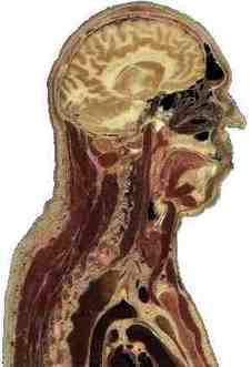
a / A cross-sectional view of a human body, showing the vocal tract.
6.2.1 Reflection, transmission, and absorption
Reflection and transmission
Sound waves can echo back from a cliff, and light waves are reflected from the surface of a pond. We use the word reflection, normally applied only to light waves in ordinary speech, to describe any such case of a wave rebounding from a barrier. Figure (a) shows a circular water wave being reflected from a straight wall. In this chapter, we will concentrate mainly on reflection of waves that move in one dimension, as in figure c/1.
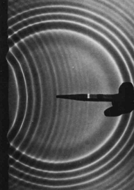
b / Circular water waves are reflected from a boundary on the left. (PSSC Physics)
Wave reflection does not surprise us. After all, a material object such as a rubber ball would bounce back in the same way. But waves are not objects, and there are some surprises in store.
First, only part of the wave is usually reflected. Looking out through a window, we see light waves that passed through it, but a person standing outside would also be able to see her reflection in the glass. A light wave that strikes the glass is partly reflected and partly transmitted (passed) by the glass. The energy of the original wave is split between the two. This is different from the behavior of the rubber ball, which must go one way or the other, not both.
Second, consider what you see if you are swimming underwater and you look up at the surface. You see your own reflection. This is utterly counterintuitive, since we would expect the light waves to burst forth to freedom in the wide-open air. A material projectile shot up toward the surface would never rebound from the water-air boundary!
What is it about the difference between two media that causes waves to be partly reflected at the boundary between them? Is it their density? Their chemical composition? Ultimately all that matters is the speed of the wave in the two media. A wave is partially reflected and partially transmitted at the boundary between media in which it has different speeds. For example, the speed of light waves in window glass is about 30% less than in air, which explains why windows always make reflections. Figure c shows examples of wave pulses being reflected at the boundary between two coil springs of different weights, in which the wave speed is different.
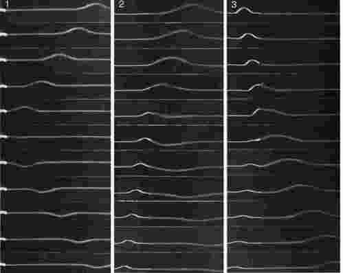
c / 1. A wave on a coil spring, initially traveling to the left, is reflected from the fixed end. 2. A wave in the lighter spring, where the wave speed is greater, travels to the left and is then partly reflected and partly transmitted at the boundary with the heavier coil spring, which has a lower wave speed. The reflection is inverted. 3. A wave moving to the right in the heavier spring is partly reflected at the boundary with the lighter spring. The reflection is uninverted. (PSSC Physics)
Reflections such as b and c/1, where a wave encounters a massive fixed object, can usually be understood on the same basis as cases like c/2 and c/3 where two media meet. Example c/1, for instance, is like a more extreme version of example c/2. If the heavy coil spring in c/2 was made heavier and heavier, it would end up acting like the fixed wall to which the light spring in c/1 has been attached.
In figure c/1, the reflected pulse is upside-down, but its depth is just as big as the original pulse's height. How does the energy of the reflected pulse compare with that of the original?
(answer in the back of the PDF version of the book)
| Example 8: Fish have internal ears. |
|---|
|
Why don't fish have ear-holes? The speed of sound waves in a fish's body is not much different from their speed in water, so sound waves are not strongly reflected from a fish's skin. They pass right through its body, so fish can have internal ears. |
| Example 9: Whale songs traveling long distances |
|---|
|
Sound waves travel at drastically different speeds through rock, water, and air. Whale songs are thus strongly reflected both at both the bottom and the surface. The sound waves can travel hundreds of miles, bouncing repeatedly between the bottom and the surface, and still be detectable. Sadly, noise pollution from ships has nearly shut down this cetacean version of the internet. |
| Example 10: Long-distance radio communication |
|---|
|
Radio communication can occur between stations on opposite sides of the planet. The mechanism is entirely similar to the one explained in the previous example, but the three media involved are the earth, the atmosphere, and the ionosphere. |
self-check:
Sonar is a method for ships and submarines to detect each other by producing sound waves and listening for echoes. What properties would an underwater object have to have in order to be invisible to sonar?
(answer in the back of the PDF version of the book)
The use of the word “reflection” naturally brings to mind the creation of an image by a mirror, but this might be confusing, because we do not normally refer to “reflection” when we look at surfaces that are not shiny. Nevertheless, reflection is how we see the surfaces of all objects, not just polished ones. When we look at a sidewalk, for example, we are actually seeing the reflecting of the sun from the concrete. The reason we don't see an image of the sun at our feet is simply that the rough surface blurs the image so drastically.
Inverted and uninverted reflections
Notice how the pulse reflected back to the right in example c/2 comes back upside-down, whereas the one reflected back to the left in c/3 returns in its original upright form. This is true for other waves as well. In general, there are two possible types of reflections, a reflection back into a faster medium and a reflection back into a slower medium. One type will always be an inverting reflection and one noninverting.
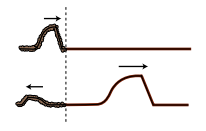
d / An uninverted reflection. The reflected pulse is reversed front to back, but is not upside-down.
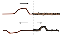
e / An inverted reflection. The reflected pulse is reversed both front to back and top to bottom.
It's important to realize that when we discuss inverted and uninverted reflections on a string, we are talking about whether the wave is flipped across the direction of motion (i.e., upside-down in these drawings). The reflected pulse will always be reversed front to back, as shown in figures d and e. This is because it is traveling in the other direction. The leading edge of the pulse is what gets reflected first, so it is still ahead when it starts back to the left --- it's just that “ahead” is now in the opposite direction.
Absorption
So far we have tacitly assumed that wave energy remains as wave energy, and is not converted to any other form. If this was true, then the world would become more and more full of sound waves, which could never escape into the vacuum of outer space. In reality, any mechanical wave consists of a traveling pattern of vibrations of some physical medium, and vibrations of matter always produce heat, as when you bend a coathangar back and forth and it becomes hot. We can thus expect that in mechanical waves such as water waves, sound waves, or waves on a string, the wave energy will gradually be converted into heat. This is referred to as absorption. The reduction in the wave's energy can also be described as a reduction in amplitude, the relationship between them being, as with a vibrating object, \(E\propto A^2\).
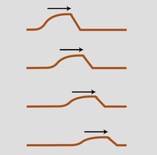
f / A pulse traveling through a highly absorptive medium.
The wave suffers a decrease in amplitude, as shown in figure f. The decrease in amplitude amounts to the same fractional change for each unit of distance covered. For example, if a wave decreases from amplitude 2 to amplitude 1 over a distance of 1 meter, then after traveling another meter it will have an amplitude of 1/2. That is, the reduction in amplitude is exponential. This can be proved as follows. By the principle of superposition, we know that a wave of amplitude 2 must behave like the superposition of two identical waves of amplitude 1. If a single amplitude-1 wave would die down to amplitude 1/2 over a certain distance, then two amplitude-1 waves superposed on top of one another to make amplitude 1+1=2 must die down to amplitude 1/2+1/2=1 over the same distance.
As a wave undergoes absorption, it loses energy. Does this mean that it slows down?
(answer in the back of the PDF version of the book)
In many cases, this frictional heating effect is quite weak. Sound waves in air, for instance, dissipate into heat extremely slowly, and the sound of church music in a cathedral may reverberate for as much as 3 or 4 seconds before it becomes inaudible. During this time it has traveled over a kilometer! Even this very gradual dissipation of energy occurs mostly as heating of the church's walls and by the leaking of sound to the outside (where it will eventually end up as heat). Under the right conditions (humid air and low frequency), a sound wave in a straight pipe could theoretically travel hundreds of kilometers before being noticeable attenuated.
In general, the absorption of mechanical waves depends a great deal on the chemical composition and microscopic structure of the medium. Ripples on the surface of antifreeze, for instance, die out extremely rapidly compared to ripples on water. For sound waves and surface waves in liquids and gases, what matters is the viscosity of the substance, i.e., whether it flows easily like water or mercury or more sluggishly like molasses or antifreeze. This explains why our intuitive expectation of strong absorption of sound in water is incorrect. Water is a very weak absorber of sound (viz. whale songs and sonar), and our incorrect intuition arises from focusing on the wrong property of the substance: water's high density, which is irrelevant, rather than its low viscosity, which is what matters.
Light is an interesting case, since although it can travel through matter, it is not itself a vibration of any material substance. Thus we can look at the star Sirius, \(10^{14}\) km away from us, and be assured that none of its light was absorbed in the vacuum of outer space during its 9-year journey to us. The Hubble Space Telescope routinely observes light that has been on its way to us since the early history of the universe, billions of years ago. Of course the energy of light can be dissipated if it does pass through matter (and the light from distant galaxies is often absorbed if there happen to be clouds of gas or dust in between).
| Example 11: Soundproofing |
|---|
|
Typical amateur musicians setting out to soundproof their garages tend to think that they should simply cover the walls with the densest possible substance. In fact, sound is not absorbed very strongly even by passing through several inches of wood. A better strategy for soundproofing is to create a sandwich of alternating layers of materials in which the speed of sound is very different, to encourage reflection. The classic design is alternating layers of fiberglass and plywood. The speed of sound in plywood is very high, due to its stiffness, while its speed in fiberglass is essentially the same as its speed in air. Both materials are fairly good sound absorbers, but sound waves passing through a few inches of them are still not going to be absorbed sufficiently. The point of combining them is that a sound wave that tries to get out will be strongly reflected at each of the fiberglass-plywood boundaries, and will bounce back and forth many times like a ping pong ball. Due to all the back-and-forth motion, the sound may end up traveling a total distance equal to ten times the actual thickness of the soundproofing before it escapes. This is the equivalent of having ten times the thickness of sound-absorbing material. |
| Example 12: Radio transmission |
|---|
|
A radio transmitting station must have a length of wire or cable connecting the amplifier to the antenna. The cable and the antenna act as two different media for radio waves, and there will therefore be partial reflection of the waves as they come from the cable to the antenna. If the waves bounce back and forth many times between the amplifier and the antenna, a great deal of their energy will be absorbed. There are two ways to attack the problem. One possibility is to design the antenna so that the speed of the waves in it is as close as possible to the speed of the waves in the cable; this minimizes the amount of reflection. The other method is to connect the amplifier to the antenna using a type of wire or cable that does not strongly absorb the waves. Partial reflection then becomes irrelevant, since all the wave energy will eventually exit through the antenna. |
Discussion Questions
◊ A sound wave that underwent a pressure-inverting reflection would have its compressions converted to expansions and vice versa. How would its energy and frequency compare with those of the original sound? Would it sound any different? What happens if you swap the two wires where they connect to a stereo speaker, resulting in waves that vibrate in the opposite way?
6.2.2 Quantitative treatment of reflection
In this subsection we analyze the reasons why reflections occur at a speed-changing boundary, predict quantitatively the intensities of reflection and transmission, and discuss how to predict for any type of wave which reflections are inverting and which are uninverting.
Why reflection occurs
To understand the fundamental reasons for what does occur at the boundary between media, let's first discuss what doesn't happen. For the sake of concreteness, consider a sinusoidal wave on a string. If the wave progresses from a heavier portion of the string, in which its velocity is low, to a lighter-weight part, in which it is high, then the equation \(v=f\lambda\) tells us that it must change its frequency, or its wavelength, or both. If only the frequency changed, then the parts of the wave in the two different portions of the string would quickly get out of step with each other, producing a discontinuity in the wave, g/1. This is unphysical, so we know that the wavelength must change while the frequency remains constant, g/2.
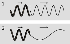
g / 1. A change in frequency without a change in wavelength would produce a discontinuity in the wave.\ 2. A simple change in wavelength without a reflection would result in a sharp kink in the wave.
But there is still something unphysical about figure g/2. The sudden change in the shape of the wave has resulted in a sharp kink at the boundary. This can't really happen, because the medium tends to accelerate in such a way as to eliminate curvature. A sharp kink corresponds to an infinite curvature at one point, which would produce an infinite acceleration, which would not be consistent with the smooth pattern of wave motion envisioned in fig. g/2. Waves can have kinks, but not stationary kinks.
We conclude that without positing partial reflection of the wave, we cannot simultaneously satisfy the requirements of (1) continuity of the wave, and (2) no sudden changes in the slope of the wave. In other words, we assume that both the wave and its derivative are continuous functions.)
Does this amount to a proof that reflection occurs? Not quite. We have only proved that certain types of wave motion are not valid solutions. In the following subsection, we prove that a valid solution can always be found in which a reflection occurs. Now in physics, we normally assume (but seldom prove formally) that the equations of motion have a unique solution, since otherwise a given set of initial conditions could lead to different behavior later on, but the Newtonian universe is supposed to be deterministic. Since the solution must be unique, and we derive below a valid solution involving a reflected pulse, we will have ended up with what amounts to a proof of reflection.
Intensity of reflection
I will now show, in the case of waves on a string, that it is possible to satisfy the physical requirements given above by constructing a reflected wave, and as a bonus this will produce an equation for the proportions of reflection and transmission and a prediction as to which conditions will lead to inverted and which to uninverted reflection. We assume only that the principle of superposition holds, which is a good approximations for waves on a string of sufficiently small amplitude.
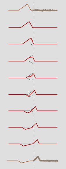
h / A pulse being partially reflected and partially transmitted at the boundary between two strings in which the wave speed is different. The top drawing shows the pulse heading to the right, toward the heaver string. For clarity, all but the first and last drawings are schematic. Once the reflected pulse begins to emerge from the boundary, it adds together with the trailing parts of the incident pulse. Their sum, shown as a wider line, is what is actually observed.
Let the unknown amplitudes of the reflected and transmitted waves be \(R\) and \(T\), respectively. An inverted reflection would be represented by a negative value of \(R\). We can without loss of generality take the incident (original) wave to have unit amplitude. Superposition tells us that if, for instance, the incident wave had double this amplitude, we could immediately find a corresponding solution simply by doubling \(R\) and \(T\).
Just to the left of the boundary, the height of the wave is given by the height 1 of the incident wave, plus the height \(R\) of the part of the reflected wave that has just been created and begun heading back, for a total height of \(1+R\). On the right side immediately next to the boundary, the transmitted wave has a height \(T\). To avoid a discontinuity, we must have
\[\begin{equation*} 1+R = T . \end{equation*}\]
Next we turn to the requirement of equal slopes on both sides of the boundary. Let the slope of the incoming wave be s immediately to the left of the junction. If the wave was 100% reflected, and without inversion, then the slope of the reflected wave would be \(-s\), since the wave has been reversed in direction. In general, the slope of the reflected wave equals \(-sR\), and the slopes of the superposed waves on the left side add up to \(s-sR\). On the right, the slope depends on the amplitude, \(T\), but is also changed by the stretching or compression of the wave due to the change in speed. If, for example, the wave speed is twice as great on the right side, then the slope is cut in half by this effect. The slope on the right is therefore \(s(v_1/v_2)T\), where \(v_1\) is the velocity in the original medium and \(v_2\) the velocity in the new medium. Equality of slopes gives \(s-sR = s(v_1/v_2)T\), or
\[\begin{equation*} 1-R = \frac{v_1}{v_2}T . \end{equation*}\]
Solving the two equations for the unknowns \(R\) and \(T\) gives
\[\begin{align*} R &= \frac{v_2-v_1}{v_2+v_1} \ \text{and} T &= \frac{2v_2}{v_2+v_1} . \end{align*}\]
The first equation shows that there is no reflection unless the two wave speeds are different, and that the reflection is inverted in reflection back into a fast medium.
The energies of the transmitted and reflected wavers always add up to the same as the energy of the original wave. There is never any abrupt loss (or gain) in energy when a wave crosses a boundary; conversion of wave energy to heat occurs for many types of waves, but it occurs throughout the medium. The equation for \(T\), surprisingly, allows the amplitude of the transmitted wave to be greater than 1, i.e., greater than that of the incident wave. This does not violate conservation of energy, because this occurs when the second string is less massive, reducing its kinetic energy, and the transmitted pulse is broader and less strongly curved, which lessens its potential energy.
Inverted and uninverted reflections in general (optional)
For waves on a string, reflections back into a faster medium are inverted, while those back into a slower medium are uninverted. Is this true for all types of waves? The rather subtle answer is that it depends on what property of the wave you are discussing.
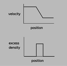
Let's start by considering wave disturbances of freeway traffic. Anyone who has driven frequently on crowded freeways has observed the phenomenon in which one driver taps the brakes, starting a chain reaction that travels backward down the freeway as each person in turn exercises caution in order to avoid rear-ending anyone. The reason why this type of wave is relevant is that it gives a simple, easily visualized example of how our description of a wave depends on which aspect of the wave we have in mind. In steadily flowing freeway traffic, both the density of cars and their velocity are constant all along the road. Since there is no disturbance in this pattern of constant velocity and density, we say that there is no wave. Now if a wave is touched off by a person tapping the brakes, we can either describe it as a region of high density or as a region of decreasing velocity.
i / A wave pattern in freeway traffic.
The freeway traffic wave is in fact a good model of a sound wave, and a sound wave can likewise be described either by the density (or pressure) of the air or by its speed. Likewise many other types of waves can be described by either of two functions, one of which is often the derivative of the other with respect to position.
Now let's consider reflections. If we observe the freeway wave in a mirror, the high-density area will still appear high in density, but velocity in the opposite direction will now be described by a negative number. A person observing the mirror image will draw the same density graph, but the velocity graph will be flipped across the \(x\) axis, and its original region of negative slope will now have positive slope. Although I don't know any physical situation that would correspond to the reflection of a traffic wave, we can immediately apply the same reasoning to sound waves, which often do get reflected, and determine that a reflection can either be density-inverting and velocity-uninverting or density-uninverting and velocity-inverting.
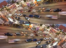
j / In the mirror image, the areas of positive excess traffic density are still positive, but the velocities of the cars have all been reversed, so areas of positive excess velocity have been turned into negative ones.
This same type of situation will occur over and over as one encounters new types of waves, and to apply the analogy we need only determine which quantities, like velocity, become negated in a mirror image and which, like density, stay the same.
A light wave, for instance, consists of a traveling pattern of electric and magnetic fields. All you need to know in order to analyze the reflection of light waves is how electric and magnetic fields behave under reflection; you don't need to know any of the detailed physics of electricity and magnetism. An electric field can be detected, for example, by the way one's hair stands on end. The direction of the hair indicates the direction of the electric field. In a mirror image, the hair points the other way, so the electric field is apparently reversed in a mirror image. The behavior of magnetic fields, however, is a little tricky. The magnetic properties of a bar magnet, for instance, are caused by the aligned rotation of the outermost orbiting electrons of the atoms. In a mirror image, the direction of rotation is reversed, say from clockwise to counterclockwise, and so the magnetic field is reversed twice: once simply because the whole picture is flipped and once because of the reversed rotation of the electrons. In other words, magnetic fields do not reverse themselves in a mirror image. We can thus predict that there will be two possible types of reflection of light waves. In one, the electric field is inverted and the magnetic field uninverted (example 23, p. 699). In the other, the electric field is uninverted and the magnetic field inverted.
6.2.3 Interference effects
If you look at the front of a pair of high-quality binoculars, you will notice a greenish-blue coating on the lenses. This is advertised as a coating to prevent reflection. Now reflection is clearly undesirable --- we want the light to go in the binoculars --- but so far I've described reflection as an unalterable fact of nature, depending only on the properties of the two wave media. The coating can't change the speed of light in air or in glass, so how can it work? The key is that the coating itself is a wave medium. In other words, we have a three-layer sandwich of materials: air, coating, and glass. We will analyze the way the coating works, not because optical coatings are an important part of your education but because it provides a good example of the general phenomenon of wave interference effects.
There are two different interfaces between media: an air-coating boundary and a coating-glass boundary. Partial reflection and partial transmission will occur at each boundary. For ease of visualization let's start by considering an equivalent system consisting of three dissimilar pieces of string tied together, and a wave pattern consisting initially of a single pulse.
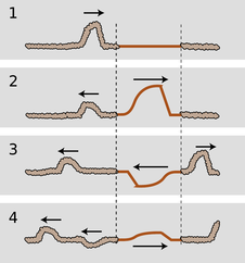
k / A pulse encounters two boundaries.
Figure k/1 shows the incident pulse moving through the heavy rope, in which its velocity is low. When it encounters the lighter-weight rope in the middle, a faster medium, it is partially reflected and partially transmitted. (The transmitted pulse is bigger, but nevertheless has only part of the original energy.) The pulse transmitted by the first interface is then partially reflected and partially transmitted by the second boundary, k/3. In figure k/4, two pulses are on the way back out to the left, and a single pulse is heading off to the right. (There is still a weak pulse caught between the two boundaries, and this will rattle back and forth, rapidly getting too weak to detect as it leaks energy to the outside with each partial reflection.)
Note how, of the two reflected pulses in k/4, one is inverted and one uninverted. One underwent reflection at the first boundary (a reflection back into a slower medium is uninverted), but the other was reflected at the second boundary (reflection back into a faster medium is inverted).
Now let's imagine what would have happened if the incoming wave pattern had been a long sinusoidal wave train instead of a single pulse. The first two waves to reemerge on the left could be in phase, l/1, or out of phase, l/2, or anywhere in between. The amount of lag between them depends entirely on the width of the middle segment of string. If we choose the width of the middle string segment correctly, then we can arrange for destructive interference to occur, l/2, with cancellation resulting in a very weak reflected wave.
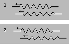
l / A sine wave has been reflected at two different boundaries, and the two reflections interfere.
This whole analysis applies directly to our original case of optical coatings. Visible light from most sources does consist of a stream of short sinusoidal wave-trains such as the ones drawn above. The only real difference between the waves-on-a-rope example and the case of an optical coating is that the first and third media are air and glass, in which light does not have the same speed. However, the general result is the same as long as the air and the glass have light-wave speeds that are either both greater than the coating's or both less than the coating's.
The business of optical coatings turns out to be a very arcane one, with a plethora of trade secrets and “black magic” techniques handed down from master to apprentice. Nevertheless, the ideas you have learned about waves in general are sufficient to allow you to come to some definite conclusions without any further technical knowledge. The self-check and discussion questions will direct you along these lines of thought.
Color corresponds to wavelength of light waves. Is it possible to choose a thickness for an optical coating that will produce destructive interference for all colors of light?
(answer in the back of the PDF version of the book)
This example was typical of a wide variety of wave interference effects. With a little guidance, you are now ready to figure out for yourself other examples such as the rainbow pattern made by a compact disc or by a layer of oil on a puddle.
Discussion Questions
- Is it possible to get complete destructive interference in an optical coating, at least for light of one specific wavelength?
- Sunlight consists of sinusoidal wave-trains containing on the order of a hundred cycles back-to-back, for a length of something like a tenth of a millimeter. What happens if you try to make an optical coating thicker than this?
- Suppose you take two microscope slides and lay one on top of the other so that one of its edges is resting on the corresponding edge of the bottom one. If you insert a sliver of paper or a hair at the opposite end, a wedge-shaped layer of air will exist in the middle, with a thickness that changes gradually from one end to the other. What would you expect to see if the slides were illuminated from above by light of a single color? How would this change if you gradually lifted the lower edge of the top slide until the two slides were finally parallel?
- An observation like the one described in discussion question C was used by Newton as evidence against the wave theory of light! If Newton didn't know about inverting and noninverting reflections, what would have seemed inexplicable to him about the region where the air layer had zero or nearly zero thickness?
6.2.4 Waves bounded on both sides
In the example of the previous section, it was theoretically true that a pulse would be trapped permanently in the middle medium, but that pulse was not central to our discussion, and in any case it was weakening severely with each partial reflection. Now consider a guitar string. At its ends it is tied to the body of the instrument itself, and since the body is very massive, the behavior of the waves when they reach the end of the string can be understood in the same way as if the actual guitar string was attached on the ends to strings that were extremely massive. Reflections are most intense when the two media are very dissimilar. Because the wave speed in the body is so radically different from the speed in the string, we should expect nearly 100% reflection.
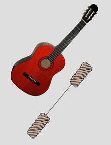
n / We model a guitar string attached to the guitar's body at both ends as a light-weight string attached to extremely heavy strings at its ends.
Although this may seem like a rather bizarre physical model of the actual guitar string, it already tells us something interesting about the behavior of a guitar that we would not otherwise have understood. The body, far from being a passive frame for attaching the strings to, is actually the exit path for the wave energy in the strings. With every reflection, the wave pattern on the string loses a tiny fraction of its energy, which is then conducted through the body and out into the air. (The string has too little cross-section to make sound waves efficiently by itself.) By changing the properties of the body, moreover, we should expect to have an effect on the manner in which sound escapes from the instrument. This is clearly demonstrated by the electric guitar, which has an extremely massive, solid wooden body. Here the dissimilarity between the two wave media is even more pronounced, with the result that wave energy leaks out of the string even more slowly. This is why an electric guitar with no electric pickup can hardly be heard at all, and it is also the reason why notes on an electric guitar can be sustained for longer than notes on an acoustic guitar.
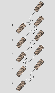
m / A pulse bounces back and forth.
If we initially create a disturbance on a guitar string, how will the reflections behave? In reality, the finger or pick will give the string a triangular shape before letting it go, and we may think of this triangular shape as a very broad “dent” in the string which will spread out in both directions. For simplicity, however, let's just imagine a wave pattern that initially consists of a single, narrow pulse traveling up the neck, m/1. After reflection from the top end, it is inverted, m/3. Now something interesting happens: figure m/5 is identical to figure m/1. After two reflections, the pulse has been inverted twice and has changed direction twice. It is now back where it started. The motion is periodic. This is why a guitar produces sounds that have a definite sensation of pitch.
self-check:
Notice that from m/1 to m/5, the pulse has passed by every point on the string exactly twice. This means that the total distance it has traveled equals 2 L, where L is the length of the string. Given this fact, what are the period and frequency of the sound it produces, expressed in terms of L and v, the velocity of the wave?
(answer in the back of the PDF version of the book)
Note that if the waves on the string obey the principle of superposition, then the velocity must be independent of amplitude, and the guitar will produce the same pitch regardless of whether it is played loudly or softly. In reality, waves on a string obey the principle of superposition approximately, but not exactly. The guitar, like just about any acoustic instrument, is a little out of tune when played loudly. (The effect is more pronounced for wind instruments than for strings, but wind players are able to compensate for it.)
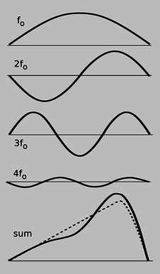
p / Any wave can be made by superposing sine waves.
Now there is only one hole in our reasoning. Suppose we somehow arrange to have an initial setup consisting of two identical pulses heading toward each other, as in figure (o). They will pass through each other, undergo a single inverting reflection, and come back to a configuration in which their positions have been exactly interchanged. This means that the period of vibration is half as long. The frequency is twice as high.

o / The period of this double-pulse pattern is half of what we'd otherwise expect.
This might seem like a purely academic possibility, since nobody actually plays the guitar with two picks at once! But in fact it is an example of a very general fact about waves that are bounded on both sides. A mathematical theorem called Fourier's theorem states that any wave can be created by superposing sine waves. Figure p shows how even by using only four sine waves with appropriately chosen amplitudes, we can arrive at a sum which is a decent approximation to the realistic triangular shape of a guitar string being plucked. The one-hump wave, in which half a wavelength fits on the string, will behave like the single pulse we originally discussed. We call its frequency \(f_\text{o}\). The two-hump wave, with one whole wavelength, is very much like the two-pulse example. For the reasons discussed above, its frequency is \(2f_\text{o}\). Similarly, the three-hump and four-hump waves have frequencies of \(3f_\text{o}\) and \(4f_\text{o}\).
Theoretically we would need to add together infinitely many such wave patterns to describe the initial triangular shape of the string exactly, although the amplitudes required for the very high frequency parts would be very small, and an excellent approximation could be achieved with as few as ten waves.
We thus arrive at the following very general conclusion. Whenever a wave pattern exists in a medium bounded on both sides by media in which the wave speed is very different, the motion can be broken down into the motion of a (theoretically infinite) series of sine waves, with frequencies \(f_\text{o},\ 2f_\text{o},\ 3f_\text{o},\ ...\) Except for some technical details, to be discussed below, this analysis applies to a vast range of sound-producing systems, including the air column within the human vocal tract. Because sounds composed of this kind of pattern of frequencies are so common, our ear-brain system has evolved so as to perceive them as a single, fused sensation of tone.
Musical applications
Many musicians claim to be able to pick out by ear several of the frequencies \(2f_\text{o}\), \(3f_\text{o}\), ..., called overtones or harmonics of the fundamental \(f_\text{o}\), but they are kidding themselves. In reality, the overtone series has two important roles in music, neither of which depends on this fictitious ability to “hear out” the individual overtones.
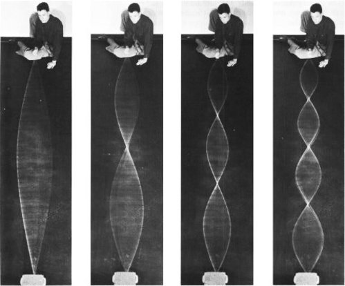
s / Standing waves on a rope. (PSSC Physics.)
First, the relative strengths of the overtones is an important part of the personality of a sound, called its timbre (rhymes with “amber”). The characteristic tone of the brass instruments, for example, is a sound that starts out with a very strong harmonic series extending up to very high frequencies, but whose higher harmonics die down drastically as the attack changes to the sustained portion of the note.
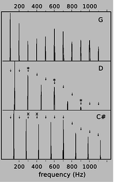
q / Graphs of loudness versus frequency for the vowel “ah,” sung as three different musical notes. G is consonant with D, since every overtone of G that is close to an overtone of D (marked “*”) is at exactly the same frequency. G and C\(\sharp\) are dissonant together, since some of the overtones of G (marked “x”) are close to, but not right on top of, those of C\(\sharp\).
Second, although the ear cannot separate the individual harmonics of a single musical tone, it is very sensitive to clashes between the overtones of notes played simultaneously, i.e., in harmony. We tend to perceive a combination of notes as being dissonant if they have overtones that are close but not the same. Roughly speaking, strong overtones whose frequencies differ by more than 1% and less than 10% cause the notes to sound dissonant. It is important to realize that the term “dissonance” is not a negative one in music. No matter how long you search the radio dial, you will never hear more than three seconds of music without at least one dissonant combination of notes. Dissonance is a necessary ingredient in the creation of a musical cycle of tension and release. Musically knowledgeable people do not usually use the word “dissonant” as a criticism of music, and if they do, what they are really saying is that the dissonance has been used in a clumsy way, or without providing any contrast between dissonance and consonance.
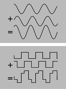
r / If you take a sine wave and make a copy of it shifted over, their sum is still a sine wave. The same is not true for a square wave.
Standing waves
Figure s shows sinusoidal wave patterns made by shaking a rope. I used to enjoy doing this at the bank with the pens on chains, back in the days when people actually went to the bank. You might think that I and the person in the photos had to practice for a long time in order to get such nice sine waves. In fact, a sine wave is the only shape that can create this kind of wave pattern, called a standing wave, which simply vibrates back and forth in one place without moving. The sine wave just creates itself automatically when you find the right frequency, because no other shape is possible.
If you think about it, it's not even obvious that sine waves should be able to do this trick. After all, waves are supposed to travel at a set speed, aren't they? The speed isn't supposed to be zero! Well, we can actually think of a standing wave as a superposition of a moving sine wave with its own reflection, which is moving the opposite way. Sine waves have the unique mathematical property that the sum of sine waves of equal wavelength is simply a new sine wave with the same wavelength. As the two sine waves go back and forth, they always cancel perfectly at the ends, and their sum appears to stand still.
Standing wave patterns are rather important, since atoms are really standing-wave patterns of electron waves. You are a standing wave!
Standing-wave patterns of air columns
The air column inside a wind instrument behaves very much like the wave-on-a-string example we've been concentrating on so far, the main difference being that we may have either inverting or noninverting reflections at the ends.
Some organ pipes are closed at both ends. The speed of sound is different in metal than in air, so there is a strong reflection at the closed ends, and we can have standing waves. These reflections are both density-noninverting, so we get symmetric standing-wave patterns, such as the one shown in figure u/1.
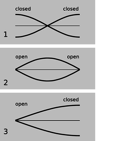
u / Graphs of excess density versus position for the lowest-frequency standing waves of three types of air columns. Points on the axis have normal air density.
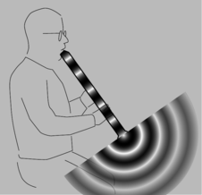
t / Surprisingly, sound waves undergo partial reflection at the open ends of tubes as well as closed ones.
Figure t shows the sound waves in and around a bamboo Japanese flute called a shakuhachi, which is open at both ends of the air column. We can only have a standing wave pattern if there are reflections at the ends, but that is very counterintuitive --- why is there any reflection at all, if the sound wave is free to emerge into open space, and there is no change in medium? Recall the reason why we got reflections at a change in medium: because the wavelength changes, so the wave has to readjust itself from one pattern to another, and the only way it can do that without developing a kink is if there is a reflection. Something similar is happening here. The only difference is that the wave is adjusting from being a plane wave to being a spherical wave. The reflections at the open ends are density-inverting, u/2, so the wave pattern is pinched off at the ends. Comparing panels 1 and 2 of the figure, we see that although the wave pattens are different, in both cases the wavelength is the same: in the lowest-frequency standing wave, half a wavelength fits inside the tube. Thus, it isn't necessary to memorize which type of reflection is inverting and which is inverting. It's only necessary to know that the tubes are symmetric.
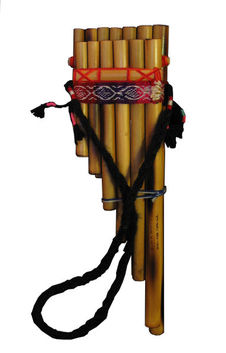
v / A pan pipe is an asymmetric air column, open at the top and closed at the bottom.
Finally, we can have an asymmetric tube: closed at one end and open at the other. A common example is the pan pipes, v, which are closed at the bottom and open at the top. The standing wave with the lowest frequency is therefore one in which 1/4 of a wavelength fits along the length of the tube, as shown in figure u/3.
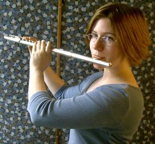
w / A concert flute looks like an asymmetric air column, open at the mouth end and closed at the other. However, its patterns of vibration are symmetric, because the embouchure hole acts like an open end.
Sometimes an instrument's physical appearance can be misleading. A concert flute, w, is closed at the mouth end and open at the other, so we would expect it to behave like an asymmetric air column; in reality, it behaves like a symmetric air column open at both ends, because the embouchure hole (the hole the player blows over) acts like an open end. The clarinet and the saxophone look similar, having a moutpiece and reed at one end and an open end at the other, but they act different. In fact the clarinet's air column has patterns of vibration that are asymmetric, the saxophone symmetric. The discrepancy comes from the difference between the conical tube of the sax and the cylindrical tube of the clarinet. The adjustment of the wave pattern from a plane wave to a spherical wave is more gradual at the flaring bell of the saxophone.
self-check:
Draw a graph of pressure versus position for the first overtone of the air column in a tube open at one end and closed at the other. This will be the next-to-longest possible wavelength that allows for a point of maximum vibration at one end and a point of no vibration at the other. How many times shorter will its wavelength be compared to the frequency of the lowest-frequency standing wave, shown in the figure? Based on this, how many times greater will its frequency be?
(answer in the back of the PDF version of the book)
| Example 13: The speed of sound |
|---|
|
We can get a rough and ready derivation of the equation for the speed of sound by analyzing the standing waves in a cylindrical air column as a special type of Helmholtz resonance (example 25 on page 332), in which the cavity happens to have the same cross-sectional area as the neck. Roughly speaking, the regions of maximum density variation act like the cavity. The regions of minimum density variation, on the other hand, are the places where the velocity of the air is varying the most; these regions throttle back the speed of the vibration, because of the inertia of the moving air. If the cylinder has cross-sectional area \(A\), then the “cavity” and “neck” parts of the wave both have lengths of something like \(\lambda/2\), and the volume of the “cavity” is about \(A\lambda/2\). We get \(v=f\lambda=(...)\sqrt{\gamma P_\text{o}/\rho}\), where the factor \((...)\) represents numerical stuff that we can't possibly hope to have gotten right with such a crude argument. The correct result is in fact \(v=\sqrt{\gamma P_\text{o}/\rho}\). Isaac Newton attempted the same calculation, but didn't understand the thermodynamic effects involved, and therefore got a result that didn't have the correct factor of \(\sqrt{\gamma}\). |
Benjamin Crowell (Fullerton College). Conceptual Physics is copyrighted with a CC-BY-SA license.


