
11.5: LRC Circuits
- Page ID
- 970

\( \newcommand{\vecs}[1]{\overset { \scriptstyle \rightharpoonup} {\mathbf{#1}} } \)
\( \newcommand{\vecd}[1]{\overset{-\!-\!\rightharpoonup}{\vphantom{a}\smash {#1}}} \)
\( \newcommand{\dsum}{\displaystyle\sum\limits} \)
\( \newcommand{\dint}{\displaystyle\int\limits} \)
\( \newcommand{\dlim}{\displaystyle\lim\limits} \)
\( \newcommand{\id}{\mathrm{id}}\) \( \newcommand{\Span}{\mathrm{span}}\)
( \newcommand{\kernel}{\mathrm{null}\,}\) \( \newcommand{\range}{\mathrm{range}\,}\)
\( \newcommand{\RealPart}{\mathrm{Re}}\) \( \newcommand{\ImaginaryPart}{\mathrm{Im}}\)
\( \newcommand{\Argument}{\mathrm{Arg}}\) \( \newcommand{\norm}[1]{\| #1 \|}\)
\( \newcommand{\inner}[2]{\langle #1, #2 \rangle}\)
\( \newcommand{\Span}{\mathrm{span}}\)
\( \newcommand{\id}{\mathrm{id}}\)
\( \newcommand{\Span}{\mathrm{span}}\)
\( \newcommand{\kernel}{\mathrm{null}\,}\)
\( \newcommand{\range}{\mathrm{range}\,}\)
\( \newcommand{\RealPart}{\mathrm{Re}}\)
\( \newcommand{\ImaginaryPart}{\mathrm{Im}}\)
\( \newcommand{\Argument}{\mathrm{Arg}}\)
\( \newcommand{\norm}[1]{\| #1 \|}\)
\( \newcommand{\inner}[2]{\langle #1, #2 \rangle}\)
\( \newcommand{\Span}{\mathrm{span}}\) \( \newcommand{\AA}{\unicode[.8,0]{x212B}}\)
\( \newcommand{\vectorA}[1]{\vec{#1}} % arrow\)
\( \newcommand{\vectorAt}[1]{\vec{\text{#1}}} % arrow\)
\( \newcommand{\vectorB}[1]{\overset { \scriptstyle \rightharpoonup} {\mathbf{#1}} } \)
\( \newcommand{\vectorC}[1]{\textbf{#1}} \)
\( \newcommand{\vectorD}[1]{\overrightarrow{#1}} \)
\( \newcommand{\vectorDt}[1]{\overrightarrow{\text{#1}}} \)
\( \newcommand{\vectE}[1]{\overset{-\!-\!\rightharpoonup}{\vphantom{a}\smash{\mathbf {#1}}}} \)
\( \newcommand{\vecs}[1]{\overset { \scriptstyle \rightharpoonup} {\mathbf{#1}} } \)
\(\newcommand{\longvect}{\overrightarrow}\)
\( \newcommand{\vecd}[1]{\overset{-\!-\!\rightharpoonup}{\vphantom{a}\smash {#1}}} \)
\(\newcommand{\avec}{\mathbf a}\) \(\newcommand{\bvec}{\mathbf b}\) \(\newcommand{\cvec}{\mathbf c}\) \(\newcommand{\dvec}{\mathbf d}\) \(\newcommand{\dtil}{\widetilde{\mathbf d}}\) \(\newcommand{\evec}{\mathbf e}\) \(\newcommand{\fvec}{\mathbf f}\) \(\newcommand{\nvec}{\mathbf n}\) \(\newcommand{\pvec}{\mathbf p}\) \(\newcommand{\qvec}{\mathbf q}\) \(\newcommand{\svec}{\mathbf s}\) \(\newcommand{\tvec}{\mathbf t}\) \(\newcommand{\uvec}{\mathbf u}\) \(\newcommand{\vvec}{\mathbf v}\) \(\newcommand{\wvec}{\mathbf w}\) \(\newcommand{\xvec}{\mathbf x}\) \(\newcommand{\yvec}{\mathbf y}\) \(\newcommand{\zvec}{\mathbf z}\) \(\newcommand{\rvec}{\mathbf r}\) \(\newcommand{\mvec}{\mathbf m}\) \(\newcommand{\zerovec}{\mathbf 0}\) \(\newcommand{\onevec}{\mathbf 1}\) \(\newcommand{\real}{\mathbb R}\) \(\newcommand{\twovec}[2]{\left[\begin{array}{r}#1 \\ #2 \end{array}\right]}\) \(\newcommand{\ctwovec}[2]{\left[\begin{array}{c}#1 \\ #2 \end{array}\right]}\) \(\newcommand{\threevec}[3]{\left[\begin{array}{r}#1 \\ #2 \\ #3 \end{array}\right]}\) \(\newcommand{\cthreevec}[3]{\left[\begin{array}{c}#1 \\ #2 \\ #3 \end{array}\right]}\) \(\newcommand{\fourvec}[4]{\left[\begin{array}{r}#1 \\ #2 \\ #3 \\ #4 \end{array}\right]}\) \(\newcommand{\cfourvec}[4]{\left[\begin{array}{c}#1 \\ #2 \\ #3 \\ #4 \end{array}\right]}\) \(\newcommand{\fivevec}[5]{\left[\begin{array}{r}#1 \\ #2 \\ #3 \\ #4 \\ #5 \\ \end{array}\right]}\) \(\newcommand{\cfivevec}[5]{\left[\begin{array}{c}#1 \\ #2 \\ #3 \\ #4 \\ #5 \\ \end{array}\right]}\) \(\newcommand{\mattwo}[4]{\left[\begin{array}{rr}#1 \amp #2 \\ #3 \amp #4 \\ \end{array}\right]}\) \(\newcommand{\laspan}[1]{\text{Span}\{#1\}}\) \(\newcommand{\bcal}{\cal B}\) \(\newcommand{\ccal}{\cal C}\) \(\newcommand{\scal}{\cal S}\) \(\newcommand{\wcal}{\cal W}\) \(\newcommand{\ecal}{\cal E}\) \(\newcommand{\coords}[2]{\left\{#1\right\}_{#2}}\) \(\newcommand{\gray}[1]{\color{gray}{#1}}\) \(\newcommand{\lgray}[1]{\color{lightgray}{#1}}\) \(\newcommand{\rank}{\operatorname{rank}}\) \(\newcommand{\row}{\text{Row}}\) \(\newcommand{\col}{\text{Col}}\) \(\renewcommand{\row}{\text{Row}}\) \(\newcommand{\nul}{\text{Nul}}\) \(\newcommand{\var}{\text{Var}}\) \(\newcommand{\corr}{\text{corr}}\) \(\newcommand{\len}[1]{\left|#1\right|}\) \(\newcommand{\bbar}{\overline{\bvec}}\) \(\newcommand{\bhat}{\widehat{\bvec}}\) \(\newcommand{\bperp}{\bvec^\perp}\) \(\newcommand{\xhat}{\widehat{\xvec}}\) \(\newcommand{\vhat}{\widehat{\vvec}}\) \(\newcommand{\uhat}{\widehat{\uvec}}\) \(\newcommand{\what}{\widehat{\wvec}}\) \(\newcommand{\Sighat}{\widehat{\Sigma}}\) \(\newcommand{\lt}{<}\) \(\newcommand{\gt}{>}\) \(\newcommand{\amp}{&}\) \(\definecolor{fillinmathshade}{gray}{0.9}\)The long road leading from the light bulb to the computer started with one very important step: the introduction of feedback into electronic circuits. Although the principle of feedback has been understood and applied to mechanical systems for centuries, and to electrical ones since the early twentieth century, for most of us the word evokes an image of Jimi Hendrix (or some more recent guitar hero) intentionally creating earsplitting screeches, or of the school principal doing the same inadvertently in the auditorium. In the guitar example, the musician stands in front of the amp and turns it up so high that the sound waves coming from the speaker come back to the guitar string and make it shake harder. This is an example of positive feedback: the harder the string vibrates, the stronger the sound waves, and the stronger the sound waves, the harder the string vibrates. The only limit is the power-handling ability of the amplifier.
Negative feedback is equally important. Your thermostat, for example, provides negative feedback by kicking the heater off when the house gets warm enough, and by firing it up again when it gets too cold. This causes the house's temperature to oscillate back and forth within a certain range. Just as out-of-control exponential freak-outs are a characteristic behavior of positive-feedback systems, oscillation is typical in cases of negative feedback. You have already studied negative feedback extensively in section 3.3 in the case of a mechanical system, although we didn't call it that.
Capacitance and inductance
In a mechanical oscillation, energy is exchanged repetitively between potential and kinetic forms, and may also be siphoned off in the form of heat dissipated by friction. In an electrical circuit, resistors are the circuit elements that dissipate heat. What are the electrical analogs of storing and releasing the potential and kinetic energy of a vibrating object? When you think of energy storage in an electrical circuit, you are likely to imagine a battery, but even rechargeable batteries can only go through 10 or 100 cycles before they wear out. In addition, batteries are not able to exchange energy on a short enough time scale for most applications. The circuit in a musical synthesizer may be called upon to oscillate thousands of times a second, and your microwave oven operates at gigahertz frequencies. Instead of batteries, we generally use capacitors and inductors to store energy in oscillating circuits. Capacitors, which you've already encountered, store energy in electric fields. An inductor does the same with magnetic fields.
Capacitors
A capacitor's energy exists in its surrounding electric fields. It is proportional to the square of the field strength, which is proportional to the charges on the plates. If we assume the plates carry charges that are the same in magnitude, \(+q\) and \(-q\), then the energy stored in the capacitor must be proportional to \(q^2\). For historical reasons, we write the constant of proportionality as \(1/2C\),
\[\begin{equation*} U_C = \frac{1}{2C}q^2 . \end{equation*}\]
The constant \(C\) is a geometrical property of the capacitor, called its capacitance.

a / The symbol for a capacitor.
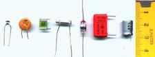
b / Some capacitors.
Based on this definition, the units of capacitance must be coulombs squared per joule, and this combination is more conveniently abbreviated as the farad, \(1\ \text{F}=1\ \text{C}^2/\text{J}\). “Condenser” is a less formal term for a capacitor. Note that the labels printed on capacitors often use MF to mean \(\mu\text{F}\), even though MF should really be the symbol for megafarads, not microfarads. Confusion doesn't result from this nonstandard notation, since picofarad and microfarad values are the most common, and it wasn't until the 1990's that even millifarad and farad values became available in practical physical sizes. Figure a shows the symbol used in schematics to represent a capacitor.
Suppose a capacitor consists of two parallel metal plates with area \(A\), and the gap between them is \(h\). The gap is small compared to the dimensions of the plates. What is the capacitance?
Solution
Since the plates are metal, the charges on each plate are free to move, and will tend to cluster themselves more densely near the edges due to the mutual repulsion of the other charges in the same plate. However, it turns out that if the gap is small, this is a small effect, so we can get away with assuming uniform charge density on each plate. The result of example 14 then applies, and for the region between the plates, we have
\[E=4\pi k\sigma=4\pi kq/ A\]
and
\[U_{e} = (1/8\pi k) E^2 Ah.\]
Substituting the first expression into the second, we find \(U_{e}=2\pi kq^2 h/ A\). Comparing this to the definition of capacitance, we end up with \(C= A/4\pi kh\).
Inductors
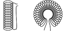
c / Two common geometries for inductors. The cylindrical shape on the left is called a solenoid.
Any current will create a magnetic field, so in fact every current-carrying wire in a circuit acts as an inductor! However, this type of “stray” inductance is typically negligible, just as we can usually ignore the stray resistance of our wires and only take into account the actual resistors. To store any appreciable amount of magnetic energy, one usually uses a coil of wire designed specifically to be an inductor. All the loops' contribution to the magnetic field add together to make a stronger field. Unlike capacitors and resistors, practical inductors are easy to make by hand. One can for instance spool some wire around a short wooden dowel. An inductor like this, in the form cylindrical coil of wire, is called a solenoid, c, and a stylized solenoid, d, is the symbol used to represent an inductor in a circuit regardless of its actual geometry.

d / The symbol for an inductor.
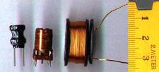
e / Some inductors.
How much energy does an inductor store? The energy density is proportional to the square of the magnetic field strength, which is in turn proportional to the current flowing through the coiled wire, so the energy stored in the inductor must be proportional to \(I^2\). We write \(L/2\) for the constant of proportionality, giving
\[\begin{equation*} U_L = \frac{L}{2}I^2 . \end{equation*}\]
As in the definition of capacitance, we have a factor of 1/2, which is purely a matter of definition. The quantity \(L\) is called the inductance of the inductor, and we see that its units must be joules per ampere squared. This clumsy combination of units is more commonly abbreviated as the henry, 1 henry = 1 \(\text{J}/\text{A}^2\). Rather than memorizing this definition, it makes more sense to derive it when needed from the definition of inductance. Many people know inductors simply as “coils,” or “chokes,” and will not understand you if you refer to an “inductor,” but they will still refer to \(L\) as the “inductance,” not the “coilance” or “chokeance!”
There is a lumped circuit approximation for inductors, just like the one for capacitors. For a capacitor, this means assuming that the electric fields are completely internal, so that components only interact via currents that flow through wires, not due to the physical overlapping of their fields in space. Similarly for an inductor, the lumped circuit approximation is the assumption that the magnetic fields are completely internal.
If two inductors are placed in series, any current that passes through the combined double inductor must pass through both its parts. If we assume the lumped circuit approximation, the two inductors' fields don't interfere with each other, so the energy is doubled for a given current. Thus by the definition of inductance, the inductance is doubled as well. In general, inductances in series add, just like resistances. The same kind of reasoning also shows that the inductance of a solenoid is approximately proportional to its length, assuming the number of turns per unit length is kept constant. (This is only approximately true, because putting two solenoids end-to-end causes the fields just outside their mouths to overlap and add together in a complicated manner. In other words, the lumped-circuit approximation may not be very good.)
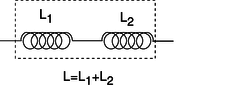
f / Inductances in series add.
When two identical capacitances are placed in parallel, any charge deposited at the terminals of the combined double capacitor will divide itself evenly between the two parts. The electric fields surrounding each capacitor will be half the intensity, and therefore store one quarter the energy. Two capacitors, each storing one quarter the energy, give half the total energy storage. Since capacitance is inversely related to energy storage, this implies that identical capacitances in parallel give double the capacitance. In general, capacitances in parallel add. This is unlike the behavior of inductors and resistors, for which series configurations give addition.
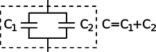
g / Capacitances in parallel add.
This is consistent with the result of example 18, which had the capacitance of a single parallel-plate capacitor proportional to the area of the plates. If we have two parallel-plate capacitors, and we combine them in parallel and bring them very close together side by side, we have produced a single capacitor with plates of double the area, and it has approximately double the capacitance, subject to any violation of the lumped-circuit approximation due to the interaction of the fields where the edges of the capacitors are joined together.
Inductances in parallel and capacitances in series are explored in homework problems 36 and 33.
Figure h/1 shows the construction of a variable capacitor out of two parallel semicircles of metal. One plate is fixed, while the other can be rotated about their common axis with a knob. The opposite charges on the two plates are attracted to one another, and therefore tend to gather in the overlapping area. This overlapping area, then, is the only area that effectively contributes to the capacitance, and turning the knob changes the capacitance. The simple design can only provide very small capacitance values, so in practice one usually uses a bank of capacitors, wired in parallel, with all the moving parts on the same shaft.
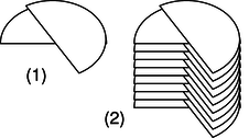
h / A variable capacitor.
Discussion Questions
◊ Suppose that two parallel-plate capacitors are wired in parallel, and are placed very close together, side by side, so that the lumped circuit approximation is not very accurate. Will the resulting capacitance be too small, or too big? Could you twist the circuit into a different shape and make the effect be the other way around, or make the effect vanish? How about the case of two inductors in series?
◊ Most practical capacitors do not have an air gap or vacuum gap between the plates; instead, they have an insulating substance called a dielectric. We can think of the molecules in this substance as dipoles that are free to rotate (at least a little), but that are not free to move around, since it is a solid.
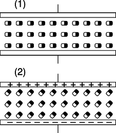
i / Discussion question B.
The figure shows a highly stylized and unrealistic way of visualizing this. We imagine that all the dipoles are initially turned sideways, (1), and that as the capacitor is charged, they all respond by turning through a certain angle, (2). (In reality, the scene might be much more random, and the alignment effect much weaker.)For simplicity, imagine inserting just one electric dipole into the vacuum gap. For a given amount of charge on the plates, how does this affect the amount of energy stored in the electric field? How does this affect the capacitance?
Now redo the analysis in terms of the mechanical work needed in order to charge up the plates.
10.5.2 Oscillations
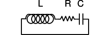
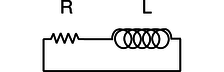
j / A series LRC circuit.
Figure j shows the simplest possible oscillating circuit. For any useful application it would actually need to include more components. For example, if it was a radio tuner, it would need to be connected to an antenna and an amplifier. Nevertheless, all the essential physics is there.

k / A mechanical analogy for the LRC circuit.
We can analyze it without any sweat or tears whatsoever, simply by constructing an analogy with a mechanical system. In a mechanical oscillator, k, we have two forms of stored energy,
\[\begin{align*} U_{spring} &= \frac{1}{2}kx^2 &(1) \\ K &= \frac{1}{2}mv^2 . &(2) \end{align*}\]
In the case of a mechanical oscillator, we have usually assumed a friction force of the form that turns out to give the nicest mathematical results, \(F=-bv\). In the circuit, the dissipation of energy into heat occurs via the resistor, with no mechanical force involved, so in order to make the analogy, we need to restate the role of the friction force in terms of energy. The power dissipated by friction equals the mechanical work it does in a time interval \(dt\), divided by \(dt\), \(P=W/dt=Fdx/dt=Fv=-bv^2\), so
\[\begin{equation*} \text{rate of heat dissipation} = -bv^2 . (3) \end{equation*}\]
self-check:
Equation (1) has \(x\) squared, and equations (2) and (3) have \(v\) squared. Because they're squared, the results don't depend on whether these variables are positive or negative. Does this make physical sense? (answer in the back of the PDF version of the book)
In the circuit, the stored forms of energy are
\[\begin{align*} U_C &= \frac{1}{2C}q^2 &(1') \\ U_L &= \frac{1}{2}LI^2 , &(2') \end{align*}\]
and the rate of heat dissipation in the resistor is
\[\begin{equation*} \text{rate of heat dissipation} = -RI^2 . (3') \end{equation*}\]
Comparing the two sets of equations, we first form analogies between quantities that represent the state of the system at some moment in time:
\[\begin{align*} x &\leftrightarrow q\\ v &\leftrightarrow I\\ \end{align*}\]
self-check:
How is \(v\) related mathematically to \(x\)? How is \(I\) connected to \(q\)? Are the two relationships analogous? (answer in the back of the PDF version of the book)
Next we relate the ones that describe the system's permanent characteristics:
\[\begin{align*} k &\leftrightarrow 1/C\\ m &\leftrightarrow L\\ b &\leftrightarrow R\\ \end{align*}\]
Since the mechanical system naturally oscillates with a frequency3 \(\omega\approx\sqrt{k/m}\), we can immediately solve the electrical version by analogy, giving
\[\begin{equation*} \omega \approx \frac{1}{\sqrt{LC}} . \end{equation*}\]
Since the resistance \(R\) is analogous to \(b\) in the mechanical case, we find that the \(Q\) (quality factor, not charge) of the resonance is inversely proportional to \(R\), and the width of the resonance is directly proportional to \(R\).
| Example 22: Tuning a radio receiver |
|---|
|
A radio receiver uses this kind of circuit to pick out the desired station. Since the receiver resonates at a particular frequency, stations whose frequencies are far off will not excite any response in the circuit. The value of \(R\) has to be small enough so that only one station at a time is picked up, but big enough so that the tuner isn't too touchy. The resonant frequency can be tuned by adjusting either \(L\) or \(C\), but variable capacitors are easier to build than variable inductors. |
| Example 23: A numerical calculation |
|---|
|
The phone company sends more than one conversation at a time over the same wire, which is accomplished by shifting each voice signal into different range of frequencies during transmission. The number of signals per wire can be maximized by making each range of frequencies (known as a bandwidth) as small as possible. It turns out that only a relatively narrow range of frequencies is necessary in order to make a human voice intelligible, so the phone company filters out all the extreme highs and lows. (This is why your phone voice sounds different from your normal voice.) \(\triangleright\) If the filter consists of an LRC circuit with a broad resonance centered around 1.0 kHz, and the capacitor is 1 \(\mu\text{F}\) (microfarad), what inductance value must be used? \(\triangleright\) Solving for \(L\), we have \[\begin{align*} L &= \frac{1}{ C\omega^2} \\ &= \frac{1}{(10^{-6}\ \text{F})(2\pi\times10^3\ \text{s}^{-1})^2} \\ &= 2.5\times10^{-3}\ \text{F}^{-1}\text{s}^2 \end{align*}\] Checking that these really are the same units as henries is a little tedious, but it builds character: \[\begin{align*} \text{F}^{-1}\text{s}^2 &= (\text{C}^2/\text{J})^{-1}\text{s}^2 \\ &= \text{J}\cdot\text{C}^{-2}\text{s}^2 \\ &= \text{J}/\text{A}^2 \\ &= \text{H} \end{align*}\] The result is 25 mH (millihenries). This is actually quite a large inductance value, and would require a big, heavy, expensive coil. In fact, there is a trick for making this kind of circuit small and cheap. There is a kind of silicon chip called an op-amp, which, among other things, can be used to simulate the behavior of an inductor. The main limitation of the op-amp is that it is restricted to low-power applications. |
10.5.3 Voltage and current
What is physically happening in one of these oscillating circuits? Let's first look at the mechanical case, and then draw the analogy to the circuit. For simplicity, let's ignore the existence of damping, so there is no friction in the mechanical oscillator, and no resistance in the electrical one.
Suppose we take the mechanical oscillator and pull the mass away from equilibrium, then release it. Since friction tends to resist the spring's force, we might naively expect that having zero friction would allow the mass to leap instantaneously to the equilibrium position. This can't happen, however, because the mass would have to have infinite velocity in order to make such an instantaneous leap. Infinite velocity would require infinite kinetic energy, but the only kind of energy that is available for conversion to kinetic is the energy stored in the spring, and that is finite, not infinite. At each step on its way back to equilibrium, the mass's velocity is controlled exactly by the amount of the spring's energy that has so far been converted into kinetic energy. After the mass reaches equilibrium, it overshoots due to its own momentum. It performs identical oscillations on both sides of equilibrium, and it never loses amplitude because friction is not available to convert mechanical energy into heat.
Now with the electrical oscillator, the analog of position is charge. Pulling the mass away from equilibrium is like depositing charges \(+q\) and \(-q\) on the plates of the capacitor. Since resistance tends to resist the flow of charge, we might imagine that with no friction present, the charge would instantly flow through the inductor (which is, after all, just a piece of wire), and the capacitor would discharge instantly. However, such an instant discharge is impossible, because it would require infinite current for one instant. Infinite current would create infinite magnetic fields surrounding the inductor, and these fields would have infinite energy. Instead, the rate of flow of current is controlled at each instant by the relationship between the amount of energy stored in the magnetic field and the amount of current that must exist in order to have that strong a field. After the capacitor reaches \(q=0\), it overshoots. The circuit has its own kind of electrical “inertia,” because if charge was to stop flowing, there would have to be zero current through the inductor. But the current in the inductor must be related to the amount of energy stored in its magnetic fields. When the capacitor is at \(q=0\), all the circuit's energy is in the inductor, so it must therefore have strong magnetic fields surrounding it and quite a bit of current going through it.
The only thing that might seem spooky here is that we used to speak as if the current in the inductor caused the magnetic field, but now it sounds as if the field causes the current. Actually this is symptomatic of the elusive nature of cause and effect in physics. It's equally valid to think of the cause and effect relationship in either way. This may seem unsatisfying, however, and for example does not really get at the question of what brings about a voltage difference across the resistor (in the case where the resistance is finite); there must be such a voltage difference, because without one, Ohm's law would predict zero current through the resistor.
Voltage, then, is what is really missing from our story so far.
Let's start by studying the voltage across a capacitor. Voltage is electrical potential energy per unit charge, so the voltage difference between the two plates of the capacitor is related to the amount by which its energy would increase if we increased the absolute values of the charges on the plates from \(q\) to \(q+dq\):
\[\begin{align*} V_C &= (U_{q+dq}-U_q)/dq \\ &= \frac{dU_C}{dq} \\ &= \frac{d}{dq}\left(\frac{1}{2C}q^2\right) \\ &= \frac{q}{C} \end{align*}\]
Many books use this as the definition of capacitance. This equation, by the way, probably explains the historical reason why \(C\) was defined so that the energy was inversely proportional to \(C\) for a given value of \(C\): the people who invented the definition were thinking of a capacitor as a device for storing charge rather than energy, and the amount of charge stored for a fixed voltage (the charge “capacity”) is proportional to \(C\).
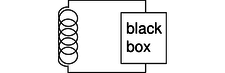
l / The inductor releases energy and gives it to the black box.
In the case of an inductor, we know that if there is a steady, constant current flowing through it, then the magnetic field is constant, and so is the amount of energy stored; no energy is being exchanged between the inductor and any other circuit element. But what if the current is changing? The magnetic field is proportional to the current, so a change in one implies a change in the other. For concreteness, let's imagine that the magnetic field and the current are both decreasing. The energy stored in the magnetic field is therefore decreasing, and by conservation of energy, this energy can't just go away --- some other circuit element must be taking energy from the inductor. The simplest example, shown in figure l, is a series circuit consisting of the inductor plus one other circuit element. It doesn't matter what this other circuit element is, so we just call it a black box, but if you like, we can think of it as a resistor, in which case the energy lost by the inductor is being turned into heat by the resistor. The junction rule tells us that both circuit elements have the same current through them, so \(I\) could refer to either one, and likewise the loop rule tells us \(V_{inductor}+V_{black\ box}=0\), so the two voltage drops have the same absolute value, which we can refer to as \(V\). Whatever the black box is, the rate at which it is taking energy from the inductor is given by \(|P|=|IV|\), so
\[\begin{align*} |IV| &= \left|\frac{dU_L}{dt}\right| \\ &= \left|\frac{d}{dt}\left( \frac{1}{2}LI^2\right) \right| \\ &= \left|LI\frac{dI}{dt}\right| ,\\ \text{or} |V| &= \left|L\frac{dI}{dt}\right| , \\ \end{align*}\]
which in many books is taken to be the definition of inductance. The direction of the voltage drop (plus or minus sign) is such that the inductor resists the change in current.
There's one very intriguing thing about this result. Suppose, for concreteness, that the black box in figure l is a resistor, and that the inductor's energy is decreasing, and being converted into heat in the resistor. The voltage drop across the resistor indicates that it has an electric field across it, which is driving the current. But where is this electric field coming from? There are no charges anywhere that could be creating it! What we've discovered is one special case of a more general principle, the principle of induction: a changing magnetic field creates an electric field, which is in addition to any electric field created by charges. (The reverse is also true: any electric field that changes over time creates a magnetic field.) Induction forms the basis for such technologies as the generator and the transformer, and ultimately it leads to the existence of light, which is a wave pattern in the electric and magnetic fields. These are all topics for chapter 11, but it's truly remarkable that we could come to this conclusion without yet having learned any details about magnetism.
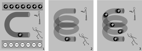
m / Electric fields made by charges, 1, and by changing magnetic fields, 2 and 3.
The cartoons in figure m compares electric fields made by charges, 1, to electric fields made by changing magnetic fields, 2-3. In m/1, two physicists are in a room whose ceiling is positively charged and whose floor is negatively charged. The physicist on the bottom throws a positively charged bowling ball into the curved pipe. The physicist at the top uses a radar gun to measure the speed of the ball as it comes out of the pipe. They find that the ball has slowed down by the time it gets to the top. By measuring the change in the ball's kinetic energy, the two physicists are acting just like a voltmeter. They conclude that the top of the tube is at a higher voltage than the bottom of the pipe. A difference in voltage indicates an electric field, and this field is clearly being caused by the charges in the floor and ceiling.
In m/2, there are no charges anywhere in the room except for the charged bowling ball. Moving charges make magnetic fields, so there is a magnetic field surrounding the helical pipe while the ball is moving through it. A magnetic field has been created where there was none before, and that field has energy. Where could the energy have come from? It can only have come from the ball itself, so the ball must be losing kinetic energy. The two physicists working together are again acting as a voltmeter, and again they conclude that there is a voltage difference between the top and bottom of the pipe. This indicates an electric field, but this electric field can't have been created by any charges, because there aren't any in the room. This electric field was created by the change in the magnetic field.
The bottom physicist keeps on throwing balls into the pipe, until the pipe is full of balls, m/3, and finally a steady current is established. While the pipe was filling up with balls, the energy in the magnetic field was steadily increasing, and that energy was being stolen from the balls' kinetic energy. But once a steady current is established, the energy in the magnetic field is no longer changing. The balls no longer have to give up energy in order to build up the field, and the physicist at the top finds that the balls are exiting the pipe at full speed again. There is no voltage difference any more. Although there is a current, \(dI/dt\) is zero.
| Example 24: Ballasts |
|---|
|
In a gas discharge tube, such as a neon sign, enough voltage is applied to a tube full of gas to ionize some of the atoms in the gas. Once ions have been created, the voltage accelerates them, and they strike other atoms, ionizing them as well and resulting in a chain reaction. This is a spark, like a bolt of lightning. But once the spark starts up, the device begins to act as though it has no resistance: more and more current flows, without the need to apply any more voltage. The power, \(P=IV\), would grow without limit, and the tube would burn itself out.
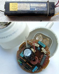
n / Ballasts for fluorescent lights. Top: a big, heavy inductor used as a ballast in an old-fashioned fluorescent bulb. Bottom: a small solid-state ballast, built into the base of a modern compact fluorescent bulb. The simplest solution is to connect an inductor, known as the “ballast,” in series with the tube, and run the whole thing on an AC voltage. During each cycle, as the voltage reaches the point where the chain reaction begins, there is a surge of current, but the inductor resists such a sudden change of current, and the energy that would otherwise have burned out the bulb is instead channeled into building a magnetic field. A common household fluorescent lightbulb consists of a gas discharge tube in which the glass is coated with a fluorescent material. The gas in the tube emits ultraviolet light, which is absorbed by the coating, and the coating then glows in the visible spectrum. Until recently, it was common for a fluroescent light's ballast to be a simple inductor, and for the whole device to be operated at the 60 Hz frequency of the electrical power lines. This caused the lights to flicker annoyingly at 120 Hz, and could also cause an audible hum, since the magnetic field surrounding the inductor could exert mechanical forces on things. These days, the trend is toward using a solid-state circuit that mimics the behavior of an inductor, but at a frequency in the kilohertz range, eliminating the flicker and hum. Modern compact fluorescent bulbs electronic have ballasts built into their bases, so they can be used as plug-in replacements for incandescent bulbs. A compact fluorescent bulb uses about 1/4 the electricity of an incandescent bulb, lasts ten times longer, and saves $30 worth of electricity over its lifetime. |
Discussion Question
◊ What happens when the physicist at the bottom in figure m/3 starts getting tired, and decreases the current?
10.5.4 Decay
Up until now I've soft-pedaled the fact that by changing the characteristics of an oscillator, it is possible to produce non-oscillatory behavior. For example, imagine taking the mass-on-a-spring system and making the spring weaker and weaker. In the limit of small \(k\), it's as though there was no spring whatsoever, and the behavior of the system is that if you kick the mass, it simply starts slowing down. For friction proportional to \(v\), as we've been assuming, the result is that the velocity approaches zero, but never actually reaches zero. This is unrealistic for the mechanical oscillator, which will not have vanishing friction at low velocities, but it is quite realistic in the case of an electrical circuit, for which the voltage drop across the resistor really does approach zero as the current approaches zero.
We do not even have to reduce \(k\) to exactly zero in order to get non-oscillatory behavior. There is actually a finite, critical value below which the behavior changes, so that the mass never even makes it through one cycle. This is the case of overdamping, discussed on page 186.
Electrical circuits can exhibit all the same behavior. For simplicity we will analyze only the cases of LRC circuits with \(L=0\) or \(C=0\).
The RC circuit

o / An RC circuit.
We first analyze the RC circuit, o. In reality one would have to “kick” the circuit, for example by briefly inserting a battery, in order to get any interesting behavior. We start with Ohm's law and the equation for the voltage across a capacitor:
\[\begin{align*} V_R &= IR \\ V_C &= q/C \end{align*}\]
The loop rule tells us
\[\begin{equation*} V_R + V_C = 0 , \end{equation*}\]
and combining the three equations results in a relationship between \(q\) and \(I\):
\[\begin{equation*} I = -\frac{1}{RC}q \end{equation*}\]
The negative sign tells us that the current tends to reduce the charge on the capacitor, i.e., to discharge it. It makes sense that the current is proportional to \(q\) : if \(q\) is large, then the attractive forces between the \(+q\) and \(-q\) charges on the plates of the capacitor are large, and charges will flow more quickly through the resistor in order to reunite. If there was zero charge on the capacitor plates, there would be no reason for current to flow. Since amperes, the unit of current, are the same as coulombs per second, it appears that the quantity \(RC\) must have units of seconds, and you can check for yourself that this is correct. \(RC\) is therefore referred to as the time constant of the circuit.
How exactly do \(I\) and \(q\) vary with time? Rewriting \(I\) as \(dq/dt\), we have
\[\begin{equation*} \frac{dq}{dt} = -\frac{1}{RC}q . \end{equation*}\]
We need a function \(q(t)\) whose derivative equals itself, but multiplied by a negative constant. A function of the form \(ae^t\), where \(e=2.718...\) is the base of natural logarithms, is the only one that has its derivative equal to itself, and \(ae^{bt}\) has its derivative equal to itself multiplied by \(b\). Thus our solution is
\[\begin{equation*} q = q_\text{o}\exp\left(-\frac{t}{RC}\right) . \end{equation*}\]
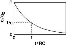
p / Over a time interval \(RC\), the charge on the capacitor is reduced by a factor of \(e\).
The RL circuit
q / An RL circuit.
The RL circuit, q, can be attacked by similar methods, and it can easily be shown that it gives
\[\begin{equation*} I = I_\text{o}\exp\left(-\frac{R}{L}t\right) . \end{equation*}\]
The RL time constant equals \(L/R\).
| Example 25 Death by solenoid; spark plugs |
|---|
|
When we suddenly break an RL circuit, what will happen? It might seem that we're faced with a paradox, since we only have two forms of energy, magnetic energy and heat, and if the current stops suddenly, the magnetic field must collapse suddenly. But where does the lost magnetic energy go? It can't go into resistive heating of the resistor, because the circuit has now been broken, and current can't flow! The way out of this conundrum is to recognize that the open gap in the circuit has a resistance which is large, but not infinite. This large resistance causes the RL time constant \(L/ R\) to be very small. The current thus continues to flow for a very brief time, and flows straight across the air gap where the circuit has been opened. In other words, there is a spark! We can determine based on several different lines of reasoning that the voltage drop from one end of the spark to the other must be very large. First, the air's resistance is large, so \(V= IR\) requires a large voltage. We can also reason that all the energy in the magnetic field is being dissipated in a short time, so the power dissipated in the spark, \(P= IV\), is large, and this requires a large value of \(V\). (\(I\) isn't large --- it is decreasing from its initial value.) Yet a third way to reach the same result is to consider the equation \(V_{L}=dI/dt\) : since the time constant is short, the time derivative \(dI/dt\) is large. This is exactly how a car's spark plugs work. Another application is to electrical safety: it can be dangerous to break an inductive circuit suddenly, because so much energy is released in a short time. There is also no guarantee that the spark will discharge across the air gap; it might go through your body instead, since your body might have a lower resistance. |
| Example 26: A spark-gap radio transmitter |
|---|
|
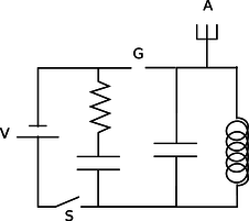
r / Example 26. Figure r shows a primitive type of radio transmitter, called a spark gap transmitter, used to send Morse code around the turn of the twentieth century. The high voltage source, V, is typically about 10,000 volts. When the telegraph switch, S, is closed, the RC circuit on the left starts charging up. An increasing voltage difference develops between the electrodes of the spark gap, G. When this voltage difference gets large enough, the electric field in the air between the electrodes causes a spark, partially discharging the RC circuit, but charging the LC circuit on the right. The LC circuit then oscillates at its resonant frequency (typically about 1 MHz), but the energy of these oscillations is rapidly radiated away by the antenna, A, which sends out radio waves (chapter 11). |
Discussion Questions
◊ A gopher gnaws through one of the wires in the DC lighting system in your front yard, and the lights turn off. At the instant when the circuit becomes open, we can consider the bare ends of the wire to be like the plates of a capacitor, with an air gap (or gopher gap) between them. What kind of capacitance value are we talking about here? What would this tell you about the \(RC\) time constant?
10.5.5 Review of complex numbers
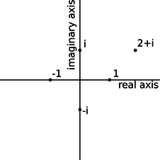
s / Visualizing complex numbers as points in a plane.
For a more detailed treatment of complex numbers, see ch. 3 of James Nearing's free book at
http://www.physics.miami.edu/nearing/mathmethods/.
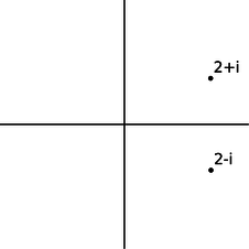
We assume there is a number, \(i\), such that \(i^2=-1\). The square roots of \(-1\) are then \(i\) and \(-i\). (In electrical engineering work, where \(i\) stands for current, \(j\) is sometimes used instead.) This gives rise to a number system, called the complex numbers, containing the real numbers as a subset. Any complex number \(z\) can be written in the form \(z=a+bi\), where \(a\) and \(b\) are real, and \(a\) and \(b\) are then referred to as the real and imaginary parts of \(z\). A number with a zero real part is called an imaginary number. The complex numbers can be visualized as a plane, with the real number line placed horizontally like the \(x\) axis of the familiar \(x-y\) plane, and the imaginary numbers running along the \(y\) axis. The complex numbers are complete in a way that the real numbers aren't: every nonzero complex number has two square roots. For example, 1 is a real number, so it is also a member of the complex numbers, and its square roots are \(-1\) and 1. Likewise, \(-1\) has square roots \(i\) and \(-i\), and the number \(i\) has square roots \(1/\sqrt{2}+i/\sqrt{2}\) and \(-1/\sqrt{2}-i/\sqrt{2}\).
Complex numbers can be added and subtracted by adding or subtracting their real and imaginary parts. Geometrically, this is the same as vector addition.
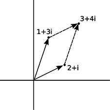
t / Addition of complex numbers is just like addition of vectors, although the real and imaginary axes don't actually represent directions in space.
The complex numbers \(a+bi\) and \(a-bi\), lying at equal distances above and below the real axis, are called complex conjugates. The results of the quadratic formula are either both real, or complex conjugates of each other. The complex conjugate of a number \(z\) is notated as \(\bar{z}\) or \(z^*\).
u / A complex number and its conjugate.
The complex numbers obey all the same rules of arithmetic as the reals, except that they can't be ordered along a single line. That is, it's not possible to say whether one complex number is greater than another. We can compare them in terms of their magnitudes (their distances from the origin), but two distinct complex numbers may have the same magnitude, so, for example, we can't say whether \(1\) is greater than \(i\) or \(i\) is greater than \(1\).
| Example 27: A square root of \(i\) |
|---|
|
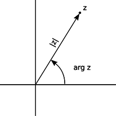
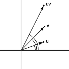
\(\triangleright\) Prove that \(1/\sqrt{2}+i/\sqrt{2}\) is a square root of \(i\). \(\triangleright\) Our proof can use any ordinary rules of arithmetic, except for ordering. \[\begin{align*} (\frac{1}{\sqrt{2}}+\frac{i}{\sqrt{2}})^2 & = \frac{1}{\sqrt{2}}\cdot\frac{1}{\sqrt{2}} +\frac{1}{\sqrt{2}}\cdot\frac{i}{\sqrt{2}} +\frac{i}{\sqrt{2}}\cdot\frac{1}{\sqrt{2}} +\frac{i}{\sqrt{2}}\cdot\frac{i}{\sqrt{2}} \\ &= \frac{1}{2}(1+i+i-1) \\ &= i \end{align*}\] Example 27 showed one method of multiplying complex numbers. However, there is another nice interpretation of complex multiplication. We define the argument of a complex number as its angle in the complex plane, measured counterclockwise from the positive real axis. Multiplying two complex numbers then corresponds to multiplying their magnitudes, and adding their arguments.
v / A complex number can be described in terms of its magnitude and argument.
w / The argument of \(uv\) is the sum of the arguments of \(u\) and \(v\). |
self-check:
Using this interpretation of multiplication, how could you find the square roots of a complex number? (answer in the back of the PDF version of the book)
| Example 28: An identity |
|---|
|
The magnitude \(|z|\) of a complex number \(z\) obeys the identity \(|z|^2=z\bar{z}\). To prove this, we first note that \(\bar{z}\) has the same magnitude as \(z\), since flipping it to the other side of the real axis doesn't change its distance from the origin. Multiplying \(z\) by \(\bar{z}\) gives a result whose magnitude is found by multiplying their magnitudes, so the magnitude of \(z\bar{z}\) must therefore equal \(|z|^2\). Now we just have to prove that \(z\bar{z}\) is a positive real number. But if, for example, \(z\) lies counterclockwise from the real axis, then \(\bar{z}\) lies clockwise from it. If \(z\) has a positive argument, then \(\bar{z}\) has a negative one, or vice-versa. The sum of their arguments is therefore zero, so the result has an argument of zero, and is on the positive real axis. 4 This whole system was built up in order to make every number have square roots. What about cube roots, fourth roots, and so on? Does it get even more weird when you want to do those as well? No. The complex number system we've already discussed is sufficient to handle all of them. The nicest way of thinking about it is in terms of roots of polynomials. In the real number system, the polynomial \(x^2-1\) has two roots, i.e., two values of \(x\) (plus and minus one) that we can plug in to the polynomial and get zero. Because it has these two real roots, we can rewrite the polynomial as \((x-1)(x+1)\). However, the polynomial \(x^2+1\) has no real roots. It's ugly that in the real number system, some second-order polynomials have two roots, and can be factored, while others can't. In the complex number system, they all can. For instance, \(x^2+1\) has roots \(i\) and \(-i\), and can be factored as \((x-i)(x+i)\). In general, the fundamental theorem of algebra states that in the complex number system, any nth-order polynomial can be factored completely into \(n\) linear factors, and we can also say that it has \(n\) complex roots, with the understanding that some of the roots may be the same. For instance, the fourth-order polynomial \(x^4+x^2\) can be factored as \((x-i)(x+i)(x-0)(x-0)\), and we say that it has four roots, \(i\), \(-i\), 0, and 0, two of which happen to be the same. This is a sensible way to think about it, because in real life, numbers are always approximations anyway, and if we make tiny, random changes to the coefficients of this polynomial, it will have four distinct roots, of which two just happen to be very close to zero. |
Discussion Questions
◊ Find \(\arg i\), \(\arg(-i)\), and \(\arg 37\), where \(\arg z\) denotes the argument of the complex number \(z\).
◊ Visualize the following multiplications in the complex plane using the interpretation of multiplication in terms of multiplying magnitudes and adding arguments: \((i)(i)=-1\), \((i)(-i)=1\), \((-i)(-i)=-1\).
◊ If we visualize \(z\) as a point in the complex plane, how should we visualize \(-z\)? What does this mean in terms of arguments? Give similar interpretations for \(z^2\) and \(\sqrt{z}\).
◊ Find four different complex numbers \(z\) such that \(z^4=1\).
◊ Compute the following. Use the magnitude and argument, not the real and imaginary parts.
\[\begin{equation*} |1+i| , \arg(1+i) , \left|\frac{1}{1+i}\right| , \arg\left(\frac{1}{1+i}\right) , \end{equation*}\]
Based on the results above, compute the real and imaginary parts of \(1/(1+i)\).
10.5.6 Euler's formula
y / Leonhard Euler (1707-1783).
Having expanded our horizons to include the complex numbers, it's natural to want to extend functions we knew and loved from the world of real numbers so that they can also operate on complex numbers. The only really natural way to do this in general is to use Taylor series. A particularly beautiful thing happens with the functions \(e^x\), \(\sin x\), and \(\cos x\):
\[\begin{align*} e^x &= 1 + \frac{1}{2!}x^2 + \frac{1}{3!}x^3 + ... \\ \cos x &= 1 - \frac{1}{2!}x^2 + \frac{1}{4!}x^4 - ... \\ \sin x &= x - \frac{1}{3!}x^3 + \frac{1}{5!}x^5 - ... \end{align*}\]
If \(x=i\phi\) is an imaginary number, we have
\[\begin{equation*} e^{i\phi} = \cos \phi + i \sin \phi , \end{equation*}\]
a result known as Euler's formula. The geometrical interpretation in the complex plane is shown in figure x.

x / The complex number \(e^{i\phi}\) lies on the unit circle.
Although the result may seem like something out of a freak show at first, applying the definition of the exponential function makes it clear how natural it is:
\[\begin{align*} e^x = \lim_{n\rightarrow \infty} \left(1+\frac{x}{n}\right)^n . \end{align*}\]
When \(x=i\phi\) is imaginary, the quantity \((1+i\phi/n)\) represents a number lying just above 1 in the complex plane. For large \(n\), \((1+i\phi/n)\) becomes very close to the unit circle, and its argument is the small angle \(\phi/n\). Raising this number to the nth power multiplies its argument by \(n\), giving a number with an argument of \(\phi\).
Euler's formula is used frequently in physics and engineering.
| Example 29: Trig functions in terms of complex exponentials |
|---|
|
\(\triangleright\) Write the sine and cosine functions in terms of exponentials. \(\triangleright\) Euler's formula for \(x=-i\phi\) gives \(\cos \phi - i \sin \phi\), since \(\cos(-\theta)=\cos\theta\), and \(\sin(-\theta)=-\sin\theta\). \[\begin{align*} \cos x &= \frac{e^{ix}+e^{-ix}}{2} \\ \sin x &= \frac{e^{ix}-e^{-ix}}{2i} \end{align*}\] |
| Example 30: A hard integral made easy |
|---|
|
\(\triangleright\) Evaluate \[\begin{equation*} \int e^x \cos x dx \end{equation*}\] \(\triangleright\) This seemingly impossible integral becomes easy if we rewrite the cosine in terms of exponentials: \[\begin{align*} \int e^x & \cos x dx \\ &= \int e^x \left(\frac{e^{ix}+e^{-ix}}{2}\right) dx \\ &= \frac{1}{2} \int (e^{(1+i)x}+e^{(1-i)x})dx \\ &= \frac{1}{2} \left( \frac{e^{(1+i)x}}{1+i}+\frac{e^{(1-i)x}}{1-i} \right)+ c \end{align*}\] Since this result is the integral of a real-valued function, we'd like it to be real, and in fact it is, since the first and second terms are complex conjugates of one another. If we wanted to, we could use Euler's theorem to convert it back to a manifestly real result.5 |
10.5.7 Impedance
So far we have been thinking in terms of the free oscillations of a circuit. This is like a mechanical oscillator that has been kicked but then left to oscillate on its own without any external force to keep the vibrations from dying out. Suppose an LRC circuit is driven with a sinusoidally varying voltage, such as will occur when a radio tuner is hooked up to a receiving antenna. We know that a current will flow in the circuit, and we know that there will be resonant behavior, but it is not necessarily simple to relate current to voltage in the most general case. Let's start instead with the special cases of LRC circuits consisting of only a resistance, only a capacitance, or only an inductance. We are interested only in the steady-state response.
The purely resistive case is easy. Ohm's law gives
\[\begin{equation*} I = \frac{V}{R} . \end{equation*}\]
In the purely capacitive case, the relation \(V=q/C\) lets us calculate
\[\begin{align*} I &= \frac{dq}{dt} \\ &= C \frac{dV}{dt} . \end{align*}\]
This is partly analogous to Ohm's law. For example, if we double the amplitude of a sinusoidally varying AC voltage, the derivative \(dV/dt\) will also double, and the amplitude of the sinusoidally varying current will also double. However, it is not true that \(I=V/R\), because taking the derivative of a sinusoidal function shifts its phase by 90 degrees. If the voltage varies as, for example, \(V(t)=V_\text{o}\sin (\omega t)\), then the current will be \(I(t)=\omega C V_\text{o}\cos (\omega t)\). The amplitude of the current is \(\omega C V_\text{o}\), which is proportional to \(V_\text{o}\), but it's not true that \(I(t)=V(t)/R\) for some constant \(R\).
z / In a capacitor, the current is \(90°\) ahead of the voltage in phase.
A second problem that crops up is that our entire analysis of DC resistive circuits was built on the foundation of the loop rule and the junction rule, both of which are statements about sums. To apply the junction rule to an AC circuit, for exampe, we would say that the sum of the sine waves describing the currents coming into the junction is equal (at every moment in time) to the sum of the sine waves going out. Now sinusoidal functions have a remarkable property, which is that if you add two different sinusoidal functions having the same frequency, the result is also a sinusoid with that frequency. For example, \(\cos\omega t+\sin\omega t=\sqrt{2}\sin(\omega t+\pi/4)\), which can be proved using trig identities. The trig identities can get very cumbersome, however, and there is a much easier technique involving complex numbers.
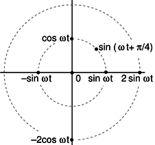
aa / Representing functions with points in polar coordinates.
Figure aa shows a useful way to visualize what's going on. When a circuit is oscillating at a frequency \(\omega\), we use points in the plane to represent sinusoidal functions with various phases and amplitudes.
self-check:
Which of the following functions can be represented in this way? \(\cos(6t-4)\), \(\cos^2t\), \(\tan t\) (answer in the back of the PDF version of the book)
The simplest examples of how to visualize this in polar coordinates are ones like \(\cos \omega t+\cos \omega t=2\cos \omega t\), where everything has the same phase, so all the points lie along a single line in the polar plot, and addition is just like adding numbers on the number line. The less trivial example \(\cos\omega t+\sin\omega t=\sqrt{2}\sin(\omega t+\pi/4)\), can be visualized as in figure ab.
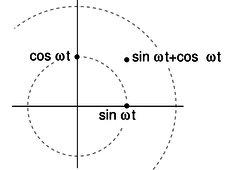
ab / Adding two sinusoidal functions.
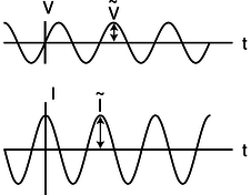
Figure ab suggests that all of this can be tied together nicely if we identify our plane with the plane of complex numbers. For example, the complex numbers 1 and \(i\) represent the functions \(\sin\omega t\) and \(\cos\omega t\). In figure z, for example, the voltage across the capacitor is a sine wave multiplied by a number that gives its amplitude, so we associate that function with a number \(\tilde{V}\) lying on the real axis. Its magnitude, \(|\tilde{V}|\), gives the amplitude in units of volts, while its argument \(\arg \tilde{V}\), gives its phase angle, which is zero. The current is a multiple of a sine wave, so we identify it with a number \(\tilde{I}\) lying on the imaginary axis. We have \(\arg\tilde{I}=90°\), and \(|\tilde{I}|\) is the amplitude of the current, in units of amperes. But comparing with our result above, we have \(|\tilde{I}|=\omega C|\tilde{V}|\). Bringing together the phase and magnitude information, we have \(\tilde{I}=i\omega C\tilde{V}\). This looks very much like Ohm's law, so we write
\[\begin{equation*} \tilde{I} = \frac{\tilde{V}}{Z_C} , \end{equation*}\]
where the quantity
\[\begin{equation*} Z_C = -\frac{i}{\omega C} , \text{[impedance of a capacitor]} \end{equation*}\]
having units of ohms, is called the impedance of the capacitor at this frequency.
It makes sense that the impedance becomes infinite at zero frequency. Zero frequency means that it would take an infinite time before the voltage would change by any amount. In other words, this is like a situation where the capacitor has been connected across the terminals of a battery and been allowed to settle down to a state where there is constant charge on both terminals. Since the electric fields between the plates are constant, there is no energy being added to or taken out of the field. A capacitor that can't exchange energy with any other circuit component is nothing more than a broken (open) circuit.
Note that we have two types of complex numbers: those that represent sinusoidal functions of time, and those that represent impedances. The ones that represent sinusoidal functions have tildes on top, which look like little sine waves.
self-check:
Why can't a capacitor have its impedance printed on it along with its capacitance? (answer in the back of the PDF version of the book)
Similar math (but this time with an integral instead of a derivative) gives
\[\begin{equation*} Z_L = i\omega L \text{[impedance of an inductor]} \end{equation*}\]
for an inductor. It makes sense that the inductor has lower impedance at lower frequencies, since at zero frequency there is no change in the magnetic field over time. No energy is added to or released from the magnetic field, so there are no induction effects, and the inductor acts just like a piece of wire with negligible resistance. The term “choke” for an inductor refers to its ability to “choke out” high frequencies.
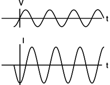
ac / The current through an inductor lags behind the voltage by a phase angle of \(90°\).
The phase relationships shown in figures z and ac can be remembered using my own mnemonic, “eVIL,” which shows that the voltage (V) leads the current (I) in an inductive circuit, while the opposite is true in a capacitive one. A more traditional mnemonic is “ELI the ICE man,” which uses the notation E for emf, a concept closely related to voltage (see p. 686).
Summarizing, the impedances of resistors, capacitors, and inductors are
\[\begin{align*} Z_R &= R\\ Z_C &= -\frac{i}{\omega C}\\ Z_L &= i\omega L . \end{align*}\]
| Example 31: Low-pass and high-pass filters |
|---|
|
An LRC circuit only responds to a certain range (band) of frequencies centered around its resonant frequency. As a filter, this is known as a bandpass filter. If you turn down both the bass and the treble on your stereo, you have created a bandpass filter. To create a high-pass or low-pass filter, we only need to insert a capacitor or inductor, respectively, in series. For instance, a very basic surge protector for a computer could be constructed by inserting an inductor in series with the computer. The desired 60 Hz power from the wall is relatively low in frequency, while the surges that can damage your computer show much more rapid time variation. Even if the surges are not sinusoidal signals, we can think of a rapid “spike” qualitatively as if it was very high in frequency --- like a high-frequency sine wave, it changes very rapidly. Inductors tend to be big, heavy, expensive circuit elements, so a simple surge protector would be more likely to consist of a capacitor in parallel with the computer. (In fact one would normally just connect one side of the power circuit to ground via a capacitor.) The capacitor has a very high impedance at the low frequency of the desired 60 Hz signal, so it siphons off very little of the current. But for a high-frequency signal, the capacitor's impedance is very small, and it acts like a zero-impedance, easy path into which the current is diverted. The main things to be careful about with impedance are that (1) the concept only applies to a circuit that is being driven sinusoidally, (2) the impedance of an inductor or capacitor is frequency-dependent. |
Discussion Question
◊ Figure z on page 607 shows the voltage and current for a capacitor. Sketch the \(q\)-\(t\) graph, and use it to give a physical explanation of the phase relationship between the voltage and current. For example, why is the current zero when the voltage is at a maximum or minimum?
◊ Figure ac on page 609 shows the voltage and current for an inductor. The power is considered to be positive when energy is being put into the inductor's magnetic field. Sketch the graph of the power, and then the graph of \(U\), the energy stored in the magnetic field, and use it to give a physical explanation of the \(P\)-\(t\) graph. In particular, discuss why the frequency is doubled on the \(P\)-\(t\) graph.
◊ Relate the features of the graph in figure ac on page 609 to the story told in cartoons in figure m/2-3 on page 598.
10.5.8 Power
How much power is delivered when an oscillating voltage is applied to an impedance? The equation \(P=IV\) is generally true, since voltage is defined as energy per unit charge, and current is defined as charge per unit time: multiplying them gives energy per unit time. In a DC circuit, all three quantities were constant, but in an oscillating (AC) circuit, all three display time variation.
A resistor
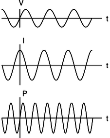
First let's examine the case of a resistor. For instance, you're probably reading this book from a piece of paper illuminated by a glowing lightbulb, which is driven by an oscillating voltage with amplitude \(V_\text{o}\). In the special case of a resistor, we know that \(I\) and \(V\) are in phase. For example, if \(V\) varies as \(V_\text{o}\cos \omega t\), then \(I\) will be a cosine as well, \(I_\text{o}\cos \omega t\). The power is then \(I_\text{o}V_\text{o}\cos^2\omega t\), which is always positive,6 and varies between 0 and \(I_\text{o}V_\text{o}\). Even if the time variation was \(\cos\omega t\) or \(\sin(\omega t+\pi/4)\), we would still have a maximum power of \(I_\text{o}V_\text{o}\), because both the voltage and the current would reach their maxima at the same time. In a lightbulb, the moment of maximum power is when the circuit is most rapidly heating the filament. At the instant when \(P=0\), a quarter of a cycle later, no current is flowing, and no electrical energy is being turned into heat. Throughout the whole cycle, the filament is getting rid of energy by radiating light.7 Since the circuit oscillates at a frequency8 of \(60\ \text{Hz}\), the temperature doesn't really have time to cycle up or down very much over the 1/60 s period of the oscillation, and we don't notice any significant variation in the brightness of the light, even with a short-exposure photograph.

ad / Power in a resistor: the rate at which electrical energy is being converted into heat.
Thus, what we really want to know is the average power, “average” meaning the average over one full cycle. Since we're covering a whole cycle with our average, it doesn't matter what phase we assume. Let's use a cosine. The total amount of energy transferred over one cycle is
\[\begin{align*} E &= \int dE \\ &= \int_0^T \frac{dE}{dt} dt , \\ \text{where $T=2\pi/\omega$ is the period.} E &= \int_0^T P dt \\ &= \int_0^T P dt \\ &= \int_0^T I_\text{o}V_\text{o} \cos^2\omega t dt \\ &= I_\text{o}V_\text{o} \int_0^T \cos^2\omega t dt \\ &= I_\text{o}V_\text{o} \int_0^T \frac{1}{2} \left(1+\cos 2\omega t\right) dt \\ \text{The reason for using the trig identity $\cos^2 x=(1+\cos 2 x)/2$ in the last step is that it lets us get the answer without doing a hard integral. Over the course of one full cycle, the quantity $\cos 2\omega t$ goes positive, negative, positive, and negative again, so the integral of it is zero. We then have} E &= I_\text{o}V_\text{o} \int_0^T \frac{1}{2} dt \\ &= \frac{I_\text{o}V_\text{o}T}{2} \end{align*}\]
The average power is
\[\begin{align*} P_{av} &= \frac{\text{energy transferred in one full cycle}}{\text{time for one full cycle}} \\ &= \frac{I_\text{o}V_\text{o}T/2}{T} \\ &= \frac{I_\text{o}V_\text{o}}{2} ,\\ \end{align*}\]
i.e., the average is half the maximum. The power varies from \(0\) to \(I_\text{o}V_\text{o}\), and it spends equal amounts of time above and below the maximum, so it isn't surprising that the average power is half-way in between zero and the maximum. Summarizing, we have
\[\begin{align*} P_{av} &= \frac{I_\text{o}V_\text{o}}{2} \text{[average power in a resistor]}\\ \end{align*}\]
for a resistor.
RMS quantities
Suppose one day the electric company decided to start supplying your electricity as DC rather than AC. How would the DC voltage have to be related to the amplitude \(V_\text{o}\) of the AC voltage previously used if they wanted your lightbulbs to have the same brightness as before? The resistance of the bulb, \(R\), is a fixed value, so we need to relate the power to the voltage and the resistance, eliminating the current. In the DC case, this gives \(P=IV=(V/R)V=V^2/R\). (For DC, \(P\) and \(P_{av}\) are the same.) In the AC case, \(P_{av} = I_\text{o}V_\text{o}/2=V_\text{o}^2/2R\). Since there is no factor of 1/2 in the DC case, the same power could be provided with a DC voltage that was smaller by a factor of \(1/\sqrt{2}\). Although you will hear people say that household voltage in the U.S. is 110 V, its amplitude is actually \((110\ \text{V})\times\sqrt{2}\approx160\ \text{V}\). The reason for referring to \(V_\text{o}/\sqrt{2}\) as “the” voltage is that people who are naive about AC circuits can plug \(V_\text{o}/\sqrt{2}\) into a familiar DC equation like \(P=V^2/R\) and get the right average answer. The quantity \(V_\text{o}/\sqrt{2}\) is called the “RMS” voltage, which stands for “root mean square.” The idea is that if you square the function \(V(t)\), take its average (mean) over one cycle, and then take the square root of that average, you get \(V_\text{o}/\sqrt{2}\). Many digital meters provide RMS readouts for measuring AC voltages and currents.
A capacitor
For a capacitor, the calculation starts out the same, but ends up with a twist. If the voltage varies as a cosine, \(V_\text{o}\cos \omega t\), then the relation \(I=CdV/dt\) tells us that the current will be some constant multiplied by minus the sine, \(-V_\text{o}\sin \omega t\). The integral we did in the case of a resistor now becomes
\[\begin{equation*} E = \int_0^T -I_\text{o}V_\text{o} \sin \omega t \cos \omega t dt ,\\ \end{equation*}\]
and based on figure ae, you can easily convince yourself that over the course of one full cycle, the power spends two quarter-cycles being negative and two being positive. In other words, the average power is zero!
ae / Power in a capacitor: the rate at which energy is being stored in (+) or removed from (-) the electric field.
Why is this? It makes sense if you think in terms of energy. A resistor converts electrical energy to heat, never the other way around. A capacitor, however, merely stores electrical energy in an electric field and then gives it back. For a capacitor,
\[\begin{align*} P_{av} &= 0 \text{[average power in a capacitor]}\\ \end{align*}\]
Notice that although the average power is zero, the power at any given instant is not typically zero, as shown in figure ae. The capacitor does transfer energy: it's just that after borrowing some energy, it always pays it back in the next quarter-cycle.
An inductor
The analysis for an inductor is similar to that for a capacitor: the power averaged over one cycle is zero. Again, we're merely storing energy temporarily in a field (this time a magnetic field) and getting it back later.
10.5.9 Impedance matching
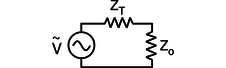
af / We wish to maximize the power delivered to the load, \(Z_\text{o}\), by adjusting its impedance.
Figure af shows a commonly encountered situation: we wish to maximize the average power, \(P_{av}\), delivered to the load for a fixed value of \(V_\text{o}\), the amplitude of the oscillating driving voltage. We assume that the impedance of the transmission line, \(Z_T\) is a fixed value, over which we have no control, but we are able to design the load, \(Z_\text{o}\), with any impedance we like. For now, we'll also assume that both impedances are resistive. For example, \(Z_T\) could be the resistance of a long extension cord, and \(Z_\text{o}\) could be a lamp at the end of it. The result generalizes immediately, however, to any kind of impedance. For example, the load could be a stereo speaker's magnet coil, which is displays both inductance and resistance. (For a purely inductive or capacitive load, \(P_{av}\) equals zero, so the problem isn't very interesting!)
Since we're assuming both the load and the transmission line are resistive, their impedances add in series, and the amplitude of the current is given by
\[\begin{align*} I_\text{o} &= \frac{V_\text{o}}{Z_\text{o}+Z_T} ,\\ \text{so} P_{av} &= I_\text{o}V_\text{o}/2 \\ &= I_\text{o}^2Z_\text{o}/2 \\ &= \frac{V_\text{o}^2Z_\text{o}}{\left(Z_\text{o}+Z_T\right)^2}/2 . \text{The maximum of this expression occurs where the derivative is zero,} 0 &= \frac{1}{2}\frac{d}{dZ_\text{o}}\left[\frac{V_\text{o}^2Z_\text{o}}{\left(Z_\text{o}+Z_T\right)^2}\right] \\ 0 &= \frac{1}{2}\frac{d}{dZ_\text{o}}\left[\frac{Z_\text{o}}{\left(Z_\text{o}+Z_T\right)^2}\right] \\ 0 &= \left(Z_\text{o}+Z_T\right)^{-2}-2Z_\text{o}\left(Z_\text{o}+Z_T\right)^{-3} \\ 0 &= \left(Z_\text{o}+Z_T\right)-2Z_\text{o} \\ Z_\text{o} &= Z_T \end{align*}\]
In other words, to maximize the power delivered to the load, we should make the load's impedance the same as the transmission line's. This result may seem surprising at first, but it makes sense if you think about it. If the load's impedance is too high, it's like opening a switch and breaking the circuit; no power is delivered. On the other hand, it doesn't pay to make the load's impedance too small. Making it smaller does give more current, but no matter how small we make it, the current will still be limited by the transmission line's impedance. As the load's impedance approaches zero, the current approaches this fixed value, and the the power delivered, \(I_\text{o}^2Z_\text{o}\), decreases in proportion to \(Z_\text{o}\).
Maximizing the power transmission by matching \(Z_T\) to \(Z_\text{o}\) is called impedance matching. For example, an 8-ohm home stereo speaker will be correctly matched to a home stereo amplifier with an internal impedance of 8 ohms, and 4-ohm car speakers will be correctly matched to a car stereo with a 4-ohm internal impedance. You might think impedance matching would be unimportant because even if, for example, we used a car stereo to drive 8-ohm speakers, we could compensate for the mismatch simply by turning the volume knob higher. This is indeed one way to compensate for any impedance mismatch, but there is always a price to pay. When the impedances are matched, half the power is dissipated in the transmission line and half in the load. By connecting a 4-ohm amplifier to an 8-ohm speaker, however, you would be setting up a situation in two watts were being dissipated as heat inside the amp for every amp being delivered to the speaker. In other words, you would be wasting energy, and perhaps burning out your amp when you turned up the volume to compensate for the mismatch.
10.5.10 Impedances in series and parallel
How do impedances combine in series and parallel? The beauty of treating them as complex numbers is that they simply combine according to the same rules you've already learned as resistances.
| Example 32: Series impedance |
|---|
|
\(\triangleright\) A capacitor and an inductor in series with each other are driven by a sinusoidally oscillating voltage. At what frequency is the current maximized? \(\triangleright\) Impedances in series, like resistances in series, add. The capacitor and inductor act as if they were a single circuit element with an impedance \[\begin{align*} Z &= Z_{L}+ Z_{C}\\ &= i\omega L-\frac{ i}{\omega C} .\\ \text{The current is then} \tilde{ I} = \frac{\tilde{ V}}{ i\omega L- i/\omega C} . \end{align*}\] We don't care about the phase of the current, only its amplitude, which is represented by the absolute value of the complex number \(\tilde{ I}\), and this can be maximized by making \(| i\omega L- i/\omega C|\) as small as possible. But there is some frequency at which this quantity is zero --- \[\begin{gather*} 0 = i\omega L-\frac{ i}{\omega C}\\ \frac{1}{\omega C} = \omega L\\ \omega = \frac{1}{\sqrt{ LC}} \end{gather*}\] At this frequency, the current is infinite! What is going on physically? This is an LRC circuit with \(R=0\). It has a resonance at this frequency, and because there is no damping, the response at resonance is infinite. Of course, any real LRC circuit will have some damping, however small (cf. figure j on page 181). |
| Example 33: Resonance with damping |
|---|
|
\(\triangleright\) What is the amplitude of the current in a series LRC circuit? \(\triangleright\) Generalizing from example 32, we add a third, real impedance: \[\begin{align*} |\tilde{ I}| &= \frac{|\tilde{ V}|}{| Z|} \\ &= \frac{|\tilde{ V}|}{| R+ i\omega L- i/\omega C|} \\ &= \frac{|\tilde{ V}|}{\sqrt{ R^2+(\omega L-1/\omega C)^2}} \end{align*}\] This result would have taken pages of algebra without the complex number technique! |
| Example 34: A second-order stereo crossover filter |
|---|
|
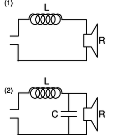
A stereo crossover filter ensures that the high frequencies go to the tweeter and the lows to the woofer. This can be accomplished simply by putting a single capacitor in series with the tweeter and a single inductor in series with the woofer. However, such a filter does not cut off very sharply. Suppose we model the speakers as resistors. (They really have inductance as well, since they have coils in them that serve as electromagnets to move the diaphragm that makes the sound.) Then the power they draw is \(I^2 R\). Putting an inductor in series with the woofer, ag/1, gives a total impedance that at high frequencies is dominated by the inductor's, so the current is proportional to \(\omega^{-1}\), and the power drawn by the woofer is proportional to \(\omega^{-2}\).
ag / Example 34. A second-order filter, like ag/2, is one that cuts off more sharply: at high frequencies, the power goes like \(\omega^{-4}\). To analyze this circuit, we first calculate the total impedance: \[\begin{equation*} Z = Z_{L}+( Z_{C}^{-1}+ Z_R^{-1})^{-1} \end{equation*}\] All the current passes through the inductor, so if the driving voltage being supplied on the left is \(\tilde{ V}_d\), we have \[\begin{equation*} \tilde{ V}_d = \tilde{ I}_{L} Z , \end{equation*}\] and we also have \[\begin{equation*} \tilde{ V}_{L} = \tilde{ I}_{L} Z_L . \end{equation*}\] The loop rule, applied to the outer perimeter of the circuit, gives \[\begin{equation*} \tilde{ V}_{d} = \tilde{ V}_{L}+\tilde{ V}_R . \end{equation*}\] Straightforward algebra now results in \[\begin{equation*} \tilde{ V}_{R} = \frac{\tilde{ V}_{d}}{1+ Z_L/ Z_{C}+ Z_{L}/ Z_R} . \end{equation*}\] At high frequencies, the \(Z_{L}/ Z_C\) term, which varies as \(\omega^2\), dominates, so \(\tilde{ V}_R\) and \(\tilde{ I}_R\) are proportional to \(\omega^{-2}\), and the power is proportional to \(\omega^{-4}\). |
Benjamin Crowell (Fullerton College). Conceptual Physics is copyrighted with a CC-BY-SA license.