
13.8: The RLC Parallel Rejector Circuit


- Last updated
- Mar 5, 2022
- Save as PDF

( \newcommand{\kernel}{\mathrm{null}\,}\)
In the circuit below, the magnitude of the admittance is least for certain values of the parameters. When you tune a radio set, you are changing the overlap area (and hence the capacitance) of the plates of a variable air-spaced capacitor so that the admittance is a minimum for a given frequency, so as to ensure the highest potential difference across the circuit. This resonance, as we shall see, does not occur for an angular frequency of exactly 1/√LC, but at an angular frequency that is approximately this if the resistance is small.
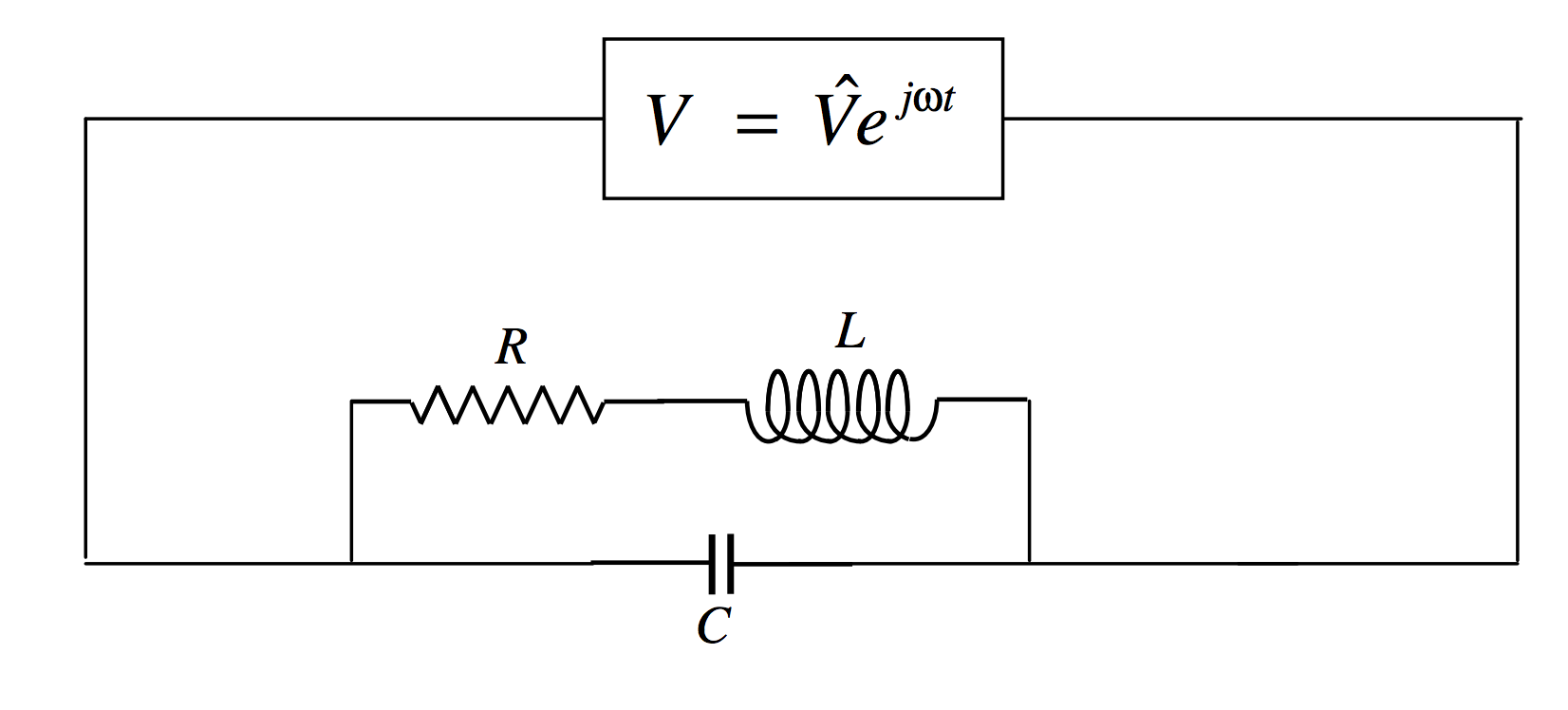
The admittance is
Y=jCω+1R+jLω.
After some routine algebra (multiply top and bottom by the conjugate; then collect real and imaginary parts), this becomes
Y=R+jω(L2Cω2+R2C−L)R2+L2ω2.
The magnitude of the admittance is least when the susceptance is zero, which occurs at an angular frequency of
ω20=1LC−R2L2.
If R<<√L/C this is approximately 1/√LC.